REVIEW 3 major objections 5 minor 29 references
Magnetic Skyrmion Field-Effect Transistors
T0 review · 3 major / 5 minor · reviewed 2026-08-14 · deepseek-v4-flash
Pith's one-line read A gate-controlled DMI step exerts an equilibrium damping-like torque that deflects skyrmions in a direction set by the product of topological charge and DMI difference, enabling multi-bit field-effect transistors.
desk verdict The DMI-step transverse kick is real and well demonstrated, but the FET concept needs to read a transient deflection that a second interface cancels; the paper never simulates that geometry. read the letter →
The pith
A machine-rendered reading of the paper's core claim, the machinery that carries it, and where it could break.
The reading
What carries the argument
The Dzyaloshinskii-Moriya interaction (DMI) is an antisymmetric exchange coupling that stabilizes chiral spin textures like skyrmions. The load-bearing object is the effective equilibrium field at a DMI step, $H_{\rm DMI,eff} = (1/M_S)[D\,\hat{\boldsymbol{y}}\times(\partial\boldsymbol{m}/\partial x) + (\delta_D/2a)(\hat{\boldsymbol{y}}\times\boldsymbol{m})]$, obtained from the interface DM energy for a planar defect. The second term is independent of current and has the symmetry of a damping-like spin-orbit torque; in the collective-coordinate equation of motion it enters as a force $F_{\rm DMI} = (-(\delta_D/2aM_S)\pi\lambda, 0)$. Combined with the gyroscopic and dissipative terms, this force yields Eqs. (6)-(7), the quantitative statement that the large transverse motion has sign set by $Q\delta_D$.
What would settle it
In a clean film with a single planar DMI step, drive a skyrmion across the step and measure the transverse displacement while independently reversing the sign of the DMI difference and the skyrmion's topological charge; the claim fails if the large deflection does not flip with the product $Q\delta_D$, or if the same deflection is not observed when the skyrmion is moved through the step without current (for example, by an oscillating magnetic field gradient).
Extended reading notes
Core claim
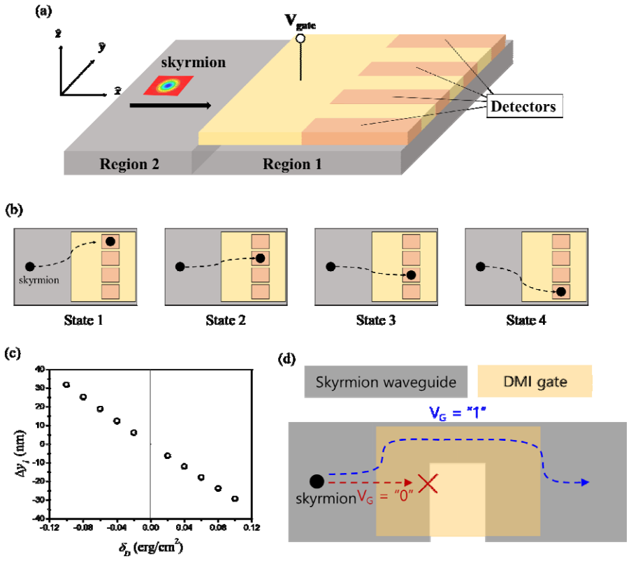
The central claim is that a spatial step in the Dzyaloshinskii-Moriya interaction (DMI) creates an additional equilibrium field with the same symmetry as a current-driven damping-like spin-orbit torque, and that this field deflects a passing skyrmion sideways by a large amount whose sign is set by the product $Q\delta_D$ of the skyrmion topological charge and the DMI difference. For $\alpha=\beta$, the collective-coordinate equations of motion give $v_x = v_s - \frac{\alpha\mathcal{D}}{\mathcal{G}^2+(\alpha\mathcal{D})^2}\left(\frac{\delta_D}{2aM_S}\right)\pi\lambda$ and $v_y = \frac{\mathcal{G}}{\mathcal{G}^2+(\alpha\mathcal{D})^2}\left(\frac{\delta_D}{2aM_S}\right)\pi\lambda$, so the transverse velocity is proportional to $\delta_D$ and to the gyromagnetic coupling $\mathcal{G}$ (hence to $Q$), while the longitudinal velocity is reduced. The trajectory consequently splits into a large deflection while crossing the step and a small residual displacement that depends only on $Q$. The authors then propose placing a gate over one region to change its DMI, making a controlled DMI step; varying the gate voltage selects the skyrmion's final $y$-position in the gated region, giving multi-bit states, and series/parallel connections of such gates implement AND and OR logic.
Load-bearing premise
The device concept assumes that the skyrmion's large sideways excursion while crossing the gated DMI step leaves it at a well-defined, stable $y$-position inside the gated region long enough for a detector to read it; the paper does not simulate the full gated device or the readout step.
Editorial extensions
If this is right
- A gate voltage that changes the DMI by roughly 4% deflects a skyrmion about 30 nm, so multilevel positioning is feasible without large voltage swings.
- The large deflection direction reverses when either the skyrmion's topological charge or the sign of the DMI difference is flipped, giving a binary control knob.
- Connecting gated DMI steps in series implements AND logic; parallel connections implement OR logic, so the same building block supports Boolean functions.
- Because the effect is linear in $\delta_D$, increasing the DMI difference gives proportionally larger deflection, easing detector placement.
- The equilibrium nature of the torque implies the deflection should also appear when the skyrmion is moved through the DMI step without current, for example by an oscillating magnetic field gradient, offering a current-free test.
Reading between the lines
- The authors treat the large motion as a crossing effect; whether the deflected position persists long enough for tunnel-magnetoresistance readout under thermal noise is not simulated, so the stability of the multi-bit state is an open question.
- Because $v_y$ in Eq. (7) is independent of the driving current while $v_x$ grows with current, the skyrmion Hall angle shrinks at high drive, implying a current-tunable trade-off between speed and deflection that could matter for racetrack designs.
- The same gate-controlled DMI-step mechanism may extend to other chiral textures such as domain walls or antiskyrmions, and possibly to antiferromagnetically coupled systems where the small $Q$-only displacement could be suppressed while the large $\delta_D$-driven deflection remains.
- The linear relation between deflection and $\delta_D$, combined with trajectory readout, suggests that skyrmion paths could serve as a local probe of interfacial DMI differences in a film.
Signed reviews
Editorial analysis
A structured set of objections, weighed in public.
Referee Report
Summary. The paper proposes a gate-controlled skyrmion field-effect transistor based on spatially inhomogeneous Dzyaloshinskii-Moriya interaction (DMI). The authors show by micromagnetic simulations that both point and planar DMI defects deflect a current-driven skyrmion transversally, producing a large transient deflection whose sign is set by the product of topological charge Q and DMI difference δ_D, plus a small residual shift whose sign depends only on Q. They model the effect via a Thiele equation with an effective damping-like torque, derive velocities in Eqs. (6) and (7), and propose a multi-bit transistor geometry (Fig. 3) with tunnel-magnetoresistance readout.
Significance. The central physics—an equilibrium damping-like torque from a DMI gradient that yields a sign-controlled transverse skyrmion deflection—is supported by direct micromagnetic simulations for both point and planar defects. This provides a concrete, falsifiable prediction (the Q·δ_D sign rule) and a plausible route to gate-controlled skyrmion logic. The paper is explicit that the large motion is a new extrinsic contribution to the skyrmion Hall effect, and the simulations are independent of the approximate Thiele model. However, the quantitative Thiele treatment is incomplete (λ undefined, F_DMI asserted) and the transistor-level claim is not tested in the actual two-interface geometry, so the device demonstration is significantly weaker than the defect-physics demonstration.
major comments (3)
- [Eqs. (5)–(7) and the planar-defect discussion] The force term F_DMI = (-(δ_D/2aM_S)πλ, 0) is introduced without derivation from the effective field in Eq. (4), and the characteristic length λ is never defined. Because Eq. (7) is the quantitative basis for the Δy1 vs δ_D relation in Fig. 3(c) and for the claim that only a 4% DMI change produces 30 nm of deflection, the missing derivation and undefined λ make the central quantitative prediction untestable.
- [Fig. 3(a)–(c) and Fig. 2] The transistor geometry has two DMI interfaces (entry into the gated region and exit from it), but the planar-defect simulation in Fig. 2 shows that a skyrmion crossing a single DMI step receives a large transverse kick at the entry edge and an opposite large kick at the exit edge, leaving only the small displacement Δy2 after full traversal. The manuscript never simulates the full gated region with its two interfaces, never specifies that the multi-bit readout must occur during the transient excursion inside region 1, and provides no detector-timing analysis to show that a tunnel-magnetoresistance readout can capture that transient. The multi-bit FET operation is therefore not established by the presented simulations.
- [Fig. 2 and Fig. 3(c)] The paper states that 'the sign of large motion is determined by the sign of Q·δ_D', but for a point defect the trajectory is deflected upward on one side and downward on the other (Fig. 1(a)); the same should occur for the two boundaries of the planar defect. The manuscript does not define whether the sign of the large motion refers to the first deflection or to the maximum excursion, which is important because the proposed FET state relies on the y-position inside the gated region during a transient deflection.
minor comments (5)
- [Abstract] The abstract contains a typo: 'The propose device' should be 'The proposed device'.
- [Eq. (4)] The symbols in Eq. (4) and the surrounding text are garbled (e.g., '𝒎ෝ ' and '𝛿' in the displayed equations); all vectors and indices should be typeset consistently so that the derivation can be followed.
- [Eq. (1)] In Eq. (1), the force is written as F = Q v × B, but the vector character of F and v is implied rather than shown, and the relationship B = -4π s_net z-hat with the gyromagnetic ratio should be stated with consistent notation.
- [Section 4, point-defect paragraph] For point defects, the text says the trajectory is 'largely deflected in the −y direction on the left side' and '+y direction on the right side'; define which of these is called the sign of the large motion, otherwise the statement 'the sign of large motion is determined by the sign of Q·δ_D' is ambiguous.
- [Fig. 3(c) and device discussion] The extraction of Δy1 from simulations is not described (e.g., at what time or after which deflection event it is measured); since the device proposal depends on this quantitative relation, a clearer description of the measurement procedure would help.
Circularity Check
No significant circularity; the core sign rule is supported by direct micromagnetic simulations and the Thiele model is not fitted.
full rationale
The paper's central claim is that the large transverse skyrmion motion obeys the sign rule v_y ~ sign(Q·δ_D). This rule is first established by direct LLG simulations in Figs. 1 and 2 for both point and planar DMI defects, and then rationalized by the Thiele model in Eqs. (5)–(7). The force F_DMI in Eq. (5) is proportional to δ_D and is presented as following from the effective DMI field of Eq. (4), which the text writes as obtained from the interface DMI energy in Eq. (3). Although Ref. [28] is self-authored and is cited for the effective DMI field, the paper does not rely on that citation alone: Eqs. (3) and (4) are displayed in the text, and the resulting sign dependence is independently corroborated by micromagnetic simulations, which are numerical solutions of the LLG equation rather than fits to the Thiele model. Ref. [25] is used only as motivational plausibility for the sign dependence, not as the derivation of the central result. No fitted parameter is later renamed as a prediction, and Eq. (7) is not calibrated to the simulations; λ is unspecified but the sign relation is not fitted. The concern that the proposed FET readout requires a transient deflection before the compensating exit kick of the second DMI interface is a device-feasibility and correctness concern, not a circularity of the derivation. Therefore no circular step is identified.
Assumptions & free parameters
free parameters (2)
- λ (characteristic skyrmion length)
- a (lattice constant)
assumptions (4)
- domain assumption The skyrmion dynamics obey the Thiele equation with a gyrotropic term, a dissipative term, and an additive DMI force (Eq. 5).
- domain assumption The effective field from inhomogeneous DMI in Eq. (4), derived in Ref. [28], applies to skyrmions.
- ad hoc to paper Setting α = β removes the intrinsic skyrmion Hall effect, isolating the extrinsic contribution.
- domain assumption The planar defect is wider than the skyrmion, so the large transverse motion is well defined and readable.
Cite this review
Pith. "Pith review of Magnetic Skyrmion Field-Effect Transistors." pith.science (2026). https://pith.science/paper/BPM7E3UJ
@misc{pith2026190804931,
  author       = {Pith},
  title        = {Pith review of: Magnetic Skyrmion Field-Effect Transistors},
  year         = {2026},
  howpublished = {\url{https://pith.science/paper/BPM7E3UJ}},
  note         = {Machine review of arXiv:1908.04931}
}
read the original abstract
Magnetic skyrmions are of considerable interest for low-power memory and logic devices because of high speed at low current and high stability due to topological protection. We propose a skyrmion field-effect transistor based on a gate-controlled Dzyaloshinskii-Moriya interaction. A key working principle of the proposed skyrmion field-effect transistor is a large transverse motion of skyrmion, caused by an effective equilibrium damping-like spin-orbit torque due to spatially inhomogeneous Dzyaloshinskii-Moriya interaction. This large transverse motion can be categorized as the skyrmion Hall effect, but has been unrecognized previously. The propose device is capable of multi-bit operation and Boolean functions, and thus is expected to serve as a low-power logic device based on the magnetic solitons.
Figures


Reference graph
Works this paper leans on
-
[1]
S. Mühlbauer, B. Binz, F. Jonietz, C. Pfleiderer, A. Rosch, A. Neubauer, R. Georgii, and P. Böni, Science 323, 915-919 (2009)
work page 2009
-
[2]
X. Z. Yu, Y . Onose, N. Kanazawa, J.H. Park, J.H. Han, Y . Matsui, N. Nagaosa, and Y . Tokura, Nature 465, 901-904 (2010)
work page 2010
-
[3]
J. Sampaio, V . Cros, S. Rohart, A. Thiaville, and A. Fert, Nat. Nanotechnol. 8, 839-844 (2013)
work page 2013
-
[4]
R. Tomasello, E. Martinez, R. Zivieri, M. Carpentieri, and G. Finocchio, Sci. Rep. 4, 6784 (2014)
work page 2014
- [5]
- [6]
-
[7]
Y . Liu, N. Lei, W. Zhao, W. Liu, A. Ruotolo, H. B. Braun, and Y. Zhou, Appl. Phys. Lett. 111, 022406 (2017)
work page 2017
-
[8]
X. Chen, W. Kang, D. Zhu, X. Zhang, N. Lei, Y . Zhang, Y . Zhou, and W. Zhao, Appl. Phys. Lett. 111, 202406 (2017)
work page 2017
Show all 29 references
-
[9]
C. Song, C. Jin, J. Wang, H. Xia, J. Wang, and Q. Liu, Appl. Phys. Lett. 111, 192413 (2017)
2017
-
[10]
Everschor-Sitte, J
K. Everschor-Sitte, J. Masell, R. M. Reeve, and M. Kläui, J. Appl. Phys . 124, 240901 (2018)
2018
-
[11]
Nepal, U
R. Nepal, U. Güngördü, and A. A. Kovalev, Appl. Phys. Lett. 112, 112404 (2018). 12
2018
-
[12]
S. Luo, M. Song, X. Li, Y . Zhang, J. Hong, X. Yang, X. Zou, N. Xu, and L. You, Nano Lett. 18, 1180-1184 (2018)
2018
-
[13]
Jiang, X
W. Jiang, X. Zhang, G. Yu, W. Zhang, X. Wang, M. B. Jungfleisc h, J. E. Pearson, X. Cheng, O. Heinonen, K. L. Wang, Y . Zhou, A. Hoffmann, and S. G. E. te Velthuis, Nat. Phys. 13, 162-169 (2016)
2016
-
[14]
Litzius, I
K. Litzius, I. Lemesh, B. Krüge r, P. Bassirian, L. Caretta, K. Richter, F. Büttner, K. Sato, O. A. Tretiakov, J. Förster, R. M. Reeve, M. Weigand, I. Bykova, H. Stoll, G. Schütz, G. S. D. Beach, and M. Kläui, Nat. Phys. 13, 170-175 (2016)
2016
-
[15]
A. A. Thiele, Phys. Rev. Lett. 30, 230 (1973)
1973
-
[16]
O. A. Tretiakov, D. Clarke, G.-W. Chern, Ya. B. Bazaliy, and O. Tchernyshyov, Phys. Rev. Lett. 100, 127204 (2008)
2008
-
[17]
E. G. Tveten, A. Qaiumzadeh, O. A. Tretiakov, and A. Brataas, Phys. Rev. Lett . 110, 127208 (2013)
2013
-
[18]
Barker and O
J. Barker and O. A. Tretiakov, Phys. Rev. Lett. 116, 147203 (2016)
2016
-
[19]
Zhang, Y
X. Zhang, Y . Zhou, and M. Ezawa, Nat. Commun. 7, 10293 (2016)
2016
-
[20]
S. K. Kim, K.-J. Lee, and Y . Tserkovnyak, Phys. Rev. B 95, 140404(R) (2017)
2017
-
[21]
Hirata, D
Y . Hirata, D. H. Kim, S. K. Kim, D. K. Lee, S. H. Oh, D. Y . Kim, T. Nishimura, T. Okuno, Y . Futakawa, H. Yoshikawa, A. Tsukamoto, Y . Tserkovnyak, Y . Shiota, T. Moriyama, S. B. Choe, K.-J. Lee, and T. Ono, Nat. Nanotechnol. 14, 232–236 (2019)
2019
-
[22]
Reichhardt and C
C. Reichhardt and C. J. O. Reichhardt, New J. Phys. 18, 095005 (2016)
2016
-
[23]
Müller and A
J. Müller and A. Rosch, Phys. Rev. B 91, 054410 (2015). 13
2015
-
[24]
Kim and M.-W
J.-V . Kim and M.-W. Yoo, Appl. Phys. Lett. 110, 132404 (2017)
2017
-
[25]
Hong, S.-W
I.-S. Hong, S.-W. Lee, and K.-J. Lee, Curr. Appl. Phys. 17, 1576-1581 (2017)
2017
-
[26]
Srivastava, M
T. Srivastava, M. Schott, R. Juge, V . Křižáková, M. Belmeguenai, Y . Roussigné, A. B.- Mantel, L. Ranno, S. Pizzini, S.-M . Chérif, A. Stashkevich, S. Auffret, O. Boulle, G. Gaudin, M. Chshiev, C. Baraduc, and H. Béa, Nano Lett. 18, 4871-4877 (2018)
2018
-
[27]
Suwardy, K
J. Suwardy, K. Nawaoka, J. Cho, M. Goto, Y . Suzuki, and S. Miw a, Phys. Rev. B 98, 144432 (2018)
2018
-
[28]
Lee, J.-H
S.-J. Lee, J.-H. Moon, H.-W. Lee and K.-J. Lee, Phys. Rev. B, 96, 184433 (2017)
2017
-
[29]
Psaroudaki and D
C. Psaroudaki and D. Loss, Phys. Rev. Lett. 120, 237203 (2018). 14 Figure 1. Transverse motion of a magnetic skyrmion induced by t he interaction with a point defect. (a) 𝑄0 and 𝛿 0 , ( b ) 𝑄൏0 and 𝛿 0 , ( c ) 𝑄0 and 𝛿 ൏0 , a n d 𝑄൏ 0 and 𝛿 ൏0 . Red and blue circles in...
2018
Reviewed August 14, 2026 · model on record in the stance chip above.
Discussion (0). Continue with ORCID to comment.