REVIEW 4 major objections 5 minor 33 references
An indoor DSO-based ceiling-vision odometry system for indoor industrial environments
T0 review · 4 major / 5 minor · reviewed 2026-08-11 · deepseek-v4-flash
Pith's one-line read This paper claims that Direct Sparse Odometry, run on an upward-facing camera, can track a mobile robot's trajectory from the ceiling alone, with no assumptions about ceiling shapes or landmarks, and that the resulting relative errors are…
desk verdict A credible but incremental ceiling-DSO parameter study; the evaluation is thin and the unvalidated photometric calibration assumption is a real soft spot, but the core idea is sound enough to referee. read the letter →
The pith
A machine-rendered reading of the paper's core claim, the machinery that carries it, and where it could break.
The reading
What carries the argument
The load-bearing mechanism is DSO's photometric error, the weighted sum of Huber-norm residuals comparing raw pixel intensities of a sparse set of high-gradient points across keyframes, minimized by Gauss-Newton on the Lie algebra se(3) within a bounded optimization window. The paper deliberately simplifies the photometric image formation model by assuming a linear camera response and no vignetting (G(x)=x and V(x)=1 everywhere), so the brightness transfer is modeled only as an affine exposure correction. This direct, intensity-based optimization is what removes the need to detect or classify ceiling features, and it is also the component whose accuracy depends on the camera obeying the simplified photometric model.
What would settle it
Record a ceiling sequence with a camera known to have strong vignetting or a highly nonlinear response curve, run Ceiling-DSO exactly as described (without photometric calibration), and check whether the relative trajectory error stays in the low-centimeter range reported in the paper; if the error grows substantially or tracking fails, the claim that the simplified photometric model suffices for arbitrary ceilings is falsified. A second check is a nearly textureless white ceiling, which would test whether DSO's sparse high-gradient point selection really needs no landmarks at all.
Extended reading notes
Core claim
On the paper's own terms, the central discovery is that DSO's direct photometric formulation transfers to ceiling imagery essentially as-is: minimizing the weighted Huber-norm photometric residuals over a sliding window of keyframes is sufficient to estimate ego-motion from a ceiling, even though the scene is far above the camera and contains no engineered landmarks. The paper shows this empirically on two real trajectories in a 21 m by 15 m space with an inclined ceiling between 4 and 6 meters high, reporting relative errors that stay in the low-centimeter range for most parameter combinations and remain within acceptable bounds even below the optimal settings. It also reports that frame rate is the dominant accuracy-relevant parameter, that downscaling the image resolution does not hurt accuracy, and that a maximum optimization window of 7 keyframes offers the best accuracy-to-runtime tradeoff.
Load-bearing premise
The implementation assumes the camera's brightness response is linear and the lens has no vignetting, but the Intel RealSense cameras used have a nonlinear response and vignetting, so the photometric model that DSO optimizes is systematically wrong and the reported error rates may not transfer to other cameras or ceilings.
Editorial extensions
If this is right
- Indoor mobile robots can localize by looking up, avoiding the need to filter out moving people, robots, and forklifts from the camera image.
- Deploying ceiling-vision odometry in new buildings does not require placing markers, measuring ceiling landmarks, or assuming a particular ceiling type.
- The parameter study gives concrete operating guidance: run at about 15 frames per second with a window of 7 keyframes, and consider reducing image resolution to 424 x 240 to save compute without losing accuracy.
- The real-time speed factors reported in the paper indicate that the system can run online on an embedded industrial PC for most parameter choices, with the 30 fps / window-15 combination being the main exception.
- Future fusion with wheel encoders could supply the metric scale that monocular DSO lacks, turning Ceiling-DSO into a complete, drift-bound localization system.
Reading between the lines
- Because the system already works with a deliberately simplified photometric model (linear response, no vignetting), applying true photometric calibration to the RealSense cameras would likely reduce the reported errors further; the paper does not test this direction.
- The finding that low frame rates hurt accuracy mainly during curved motion suggests an adaptive frame-rate policy (low on straightaways, high in turns) as a natural extension, building on the paper's own observation.
- Once the authors release their custom dataset, it could become a shared benchmark for ceiling-vision odometry, filling the gap the paper identifies of having no public dataset for this task.
- Ceiling scenes are static geometrically but not photometrically (windows, lamps, shadows), so a direct test of robustness to changing illumination would be a quick way to probe how far the no-assumption claim extends.
Signed reviews
Editorial analysis
A structured set of objections, weighed in public.
Referee Report
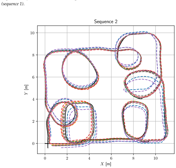
Summary. The paper presents Ceiling-DSO, an adaptation of Direct Sparse Odometry (DSO) to an upward-facing monocular camera for indoor industrial robot localization. It claims that DSO's photometric tracking works on ceilings without assumptions about landmarks or shapes, and reports 'acceptable error rates' compared to LiDAR-SLAM ground truth. The authors created a custom dataset with an industrial robot, systematically varied image size, frame rate, and optimization window size, and provide qualitative trajectory plots, relative-error plots, box plots, and runtime tables for two sequences.
Significance. If the claims hold, Ceiling-DSO would be a useful, assumption-free ceiling-vision odometry candidate for dynamic industrial environments, avoiding moving-object interference. The paper builds on a mature algorithm (DSO), so the core mechanism is plausible; its main contribution is an empirical demonstration and parameter analysis. Strengths include the real-world dataset, systematic evaluation across 24 parameter combinations per sequence, and explicit runtime and speed-factor analysis. However, the evidence base is narrow (two sequences, one building, no error bars), the photometric model is simplified without validation, no code or data are released, and the evaluation methodology leaves several load-bearing questions open. The contribution is incremental relative to the authors' ICARCV 2022 paper [1].
major comments (4)
- [Section 2, Eq. (12)] The implementation assumes a linear camera response and no vignetting (G(x)=x, V(x)=1), yet the experiments use Intel RealSense D435i/D455 cameras, whose nonlinear response and lens vignetting are not calibrated or compensated. The affine brightness parameters (a_i,b_i) in Eq. (4) cannot model spatially varying vignetting, so the photometric residuals are systematically biased if the assumption is false. Since the central claim is 'acceptable error rates', the paper must either provide photometric calibration of the cameras or include an ablation demonstrating that the reported errors are insensitive to this mismatch.
- [Section 4, Figs. 8-10] The quantitative evaluation relies entirely on qualitative trajectory plots, relative-error plots, and box plots; no overall numerical metrics (e.g., RMSE, mean/median relative error, maximum error) are reported in the text or tables. As a result, the abstract's claim of 'acceptable error rates' is not quantitatively defined or reproducible. Please report standard trajectory-error metrics for each parameter combination and sequence.
- [Section 3.3] The ground truth trajectory is produced by LaMa SLAM [30] from the safety LiDAR, but the accuracy of this SLAM solution is not quantified, and no loop-closure or map-quality assessment is provided. If LaMa's own drift is comparable to the reported relative errors, the comparison is inconclusive. The authors should report the LiDAR-SLAM trajectory accuracy (e.g., against known ground-truth geometry or a second SLAM method) or at least discuss its expected drift.
- [Section 4] The recommended parameters (15 fps, window size 7) are selected by inspecting the same two sequences used for the reported performance, without a held-out validation set; this introduces a selection bias and overstates generalizability. Additionally, the monocular scale lambda is fitted during trajectory alignment in Eq. (14), so trajectory scale error is not evaluated; the paper should report how sensitive the error rates are to the scale estimate and validate parameters on unseen sequences.
minor comments (5)
- [Throughout] There are numerous language errors (e.g., 'an ceiling-vision', 'On one hand', 'This used this embedded computer') that should be corrected.
- [Section 2] The text first states that direct methods use information from all pixels, then later describes DSO as sparse; this taxonomy should be clarified to avoid confusion.
- [Eq. (13)] The synchronization definitions of G' and P' are notationally confusing between sets and ordered sequences; please make the matching explicit.
- [Section 4] The text refers to 'plot 10' instead of 'Figure 10', and several trajectory figures lack legends within some panels; please standardize figure captions and legends.
- [Tables 1-2] The column heading 'Win.' should be expanded to 'Window size' for clarity, and the tables would benefit from a note that timings are averages over the tested sequences.
Circularity Check
The reported 'acceptable error rates' are produced by the same two sequences used to tune frame rate and window size, making the headline validation partly in-sample; the underlying DSO derivation is externally established and not circular.
-
fitted input called prediction
[Abstract; Section 3.3 Methodology; Section 4 Results and discussion]
"By adjusting DSO parameters, we identified the optimal fit for online pose estimation, resulting in acceptable error rates compared to ground truth. ... For this paper, we have chosen to showcase two specific sequences. ... we conducted a systematic evaluation by testing a total of 24 trajectories per sequence. These trajectories were generated by iterating over all possible combinations of tested parameters."
Frame rate, image size, and window size are selected by comparing all 24 parameter combinations on the same two sequences that later furnish the reported relative-error numbers. The 'optimal fit' is therefore a minimum (or near-minimum) of the error surface measured with the ground truth of those exact sequences. Reporting these errors as the system's validation is not an independent test of the ceiling-vision claim; it is an in-sample report of the tuning objective. The non-circular part is DSO's external formulation, but the paper's new empirical claim is not independently evaluated.
full rationale
The photometric derivation is not circular: Eq. (12) explicitly states the simplifying assumptions G(x)=x and V(x)=1, and the affine brightness model of Eq. (4) is inherited from DSO's published formulation. No self-citation is load-bearing: the cited prior ICARCV paper is the predecessor of this work and the SmartTrolley citation concerns the platform, not the odometry claim; DSO [12] and LaMa [30] are external sources. The principal circularity concern is empirical: the paper tunes its three operating parameters on the same two sequences used to report 'acceptable error rates,' so those rates are in-sample fits rather than predictions on unseen data. This does not void the central idea—applying DSO to an upward-facing ceiling camera—but it means the quantitative validation cannot be taken as an independent estimate of generalization. If a held-out sequence or fixed a-priori parameters had been used, the circularity score would be near zero.
Assumptions & free parameters
free parameters (3)
- Scale factor lambda (trajectory alignment) =
fitted per trajectory via Eq. (14)
- Frame rate recommendation (15 fps) =
15 fps
- Optimization window size recommendation (7) =
7
assumptions (5)
- domain assumption Pinhole camera model and standard DSO photometric model
- ad hoc to paper Linear response and no vignetting (G(x)=x, V(x)=1)
- domain assumption Planar robot motion for trajectory alignment
- domain assumption LiDAR SLAM (LaMa) trajectory is accurate ground truth
- domain assumption The ceiling has sufficient photometric gradient for DSO point selection
Cite this review
Pith. "Pith review of An indoor DSO-based ceiling-vision odometry system for indoor industrial environments." pith.science (2026). https://pith.science/paper/OD3K6AJJ
@misc{pith2026241202950,
  author       = {Pith},
  title        = {Pith review of: An indoor DSO-based ceiling-vision odometry system for indoor industrial environments},
  year         = {2026},
  howpublished = {\url{https://pith.science/paper/OD3K6AJJ}},
  note         = {Machine review of arXiv:2412.02950}
}
read the original abstract
Autonomous Mobile Robots operating in indoor industrial environments require a localization system that is reliable and robust. While Visual Odometry (VO) can offer a reasonable estimation of the robot's state, traditional VO methods encounter challenges when confronted with dynamic objects in the scene. Alternatively, an upward-facing camera can be utilized to track the robot's movement relative to the ceiling, which represents a static and consistent space. We introduce in this paper Ceiling-DSO, a ceiling-vision system based on Direct Sparse Odometry (DSO). Unlike other ceiling-vision systems, Ceiling-DSO takes advantage of the versatile formulation of DSO, avoiding assumptions about observable shapes or landmarks on the ceiling. This approach ensures the method's applicability to various ceiling types. Since no publicly available dataset for ceiling-vision exists, we created a custom dataset in a real-world scenario and employed it to evaluate our approach. By adjusting DSO parameters, we identified the optimal fit for online pose estimation, resulting in acceptable error rates compared to ground truth. We provide in this paper a qualitative and quantitative analysis of the obtained results.
Figures


Figures from the paper (8 more)



Reference graph
Works this paper leans on
-
[1]
Evaluation of a Novel DSO-based Indoor Ceiling-Vision Odometry System
Bougouffa, A.; Seignez, E.; Bouaziz, S.; Gardes, F. Evaluation of a Novel DSO-based Indoor Ceiling-Vision Odometry System. In Proceedings of the 2022 17th International Conference on Control, Automation, Robotics and Vision (ICARCV), pp. 47–53. https://doi.org/10.1109/ICARCV57592.2022.10004272
-
[30]
Fast Grid SLAM Based on Particle Filter with Scan Matching and Multithreading
Pedrosa, E.; Pereira, A.; Lau, N. Fast Grid SLAM Based on Particle Filter with Scan Matching and Multithreading. In Proceedings of the 2020 IEEE International Conference on Autonomous Robot Systems and Competitions (ICARSC). IEEE, pp. 194–199. https://doi.org/10.1109/ICARSC49921.2020.9096191
arXiv 2020
-
[2]
Application of AGV in Intelligent Logistics System
Qi, B.; Yang, Q.; Zhou, Y.Y. Application of AGV in Intelligent Logistics System. In Proceedings of the Fifth Asia International Symposium on Mechatronics (AISM 2015), pp. 1–5. https://doi.org/10.1049/cp.2015.1527
-
[3]
The OmniMate: A Guidewire- and Beacon-Free AGV for Highly Reconfigurable Applications
Borenstein, J. The OmniMate: A Guidewire- and Beacon-Free AGV for Highly Reconfigurable Applications. 38, 1993–2010. https://doi.org/10.1080/002075400188456
-
[4]
System and Design of a Compact and Heavy-Payload AGV System for Flexible Production Line
Han, L.; Qian, H.; Chung, W.K.; Hou, K.W.; Lee, K.H.; Chen, X.; Zhang, G.; Xu, Y. System and Design of a Compact and Heavy-Payload AGV System for Flexible Production Line. In Proceedings of the 2013 IEEE International Conference on Robotics and Biomimetics (ROBIO), pp. 2482–2488. https://doi.org/10.1109/ROBIO.2013.6739844
-
[5]
Introduction to Autonomous Mobile Robots, 2 ed.; The MIT Press
Siegwart, R.; Nourbakhsh, I.R.; Scaramuzza, D. Introduction to Autonomous Mobile Robots, 2 ed.; The MIT Press
-
[6]
Scaramuzza, D.; Fraundorfer, F. Visual Odometry [Tutorial]. 18, 80–92. https://doi.org/10.1109/MRA.2011.943233
arXiv 2011
-
[7]
Nister, D.; Naroditsky, O.; Bergen, J. Visual Odometry. In Proceedings of the Proceedings of the 2004 IEEE Computer Society Conference on Computer Vision and Pattern Recognition, 2004. CVPR 2004., Vol. 1, pp. I–I. https://doi.org/10.1109/CVPR.2004 .1315094
Show all 33 references
-
[8]
ORB-SLAM2: An Open-Source SLAM System for Monocular, Stereo, and RGB-D Cameras
Mur-Artal, R.; Tardós, J.D. ORB-SLAM2: An Open-Source SLAM System for Monocular, Stereo, and RGB-D Cameras. 33, 1255–
-
[9]
Swift Path Planning: Vehicle Localization by Visual Odometry Trajectory Tracking and Mapping
Awang Salleh, D.N.S.D.; Seignez, E. Swift Path Planning: Vehicle Localization by Visual Odometry Trajectory Tracking and Mapping. 06, 221–230. https://doi.org/10.1142/S2301385018500085
-
[10]
MonoSLAM: Real-Time Single Camera SLAM
Davison, A.J.; Reid, I.D.; Molton, N.D.; Stasse, O. MonoSLAM: Real-Time Single Camera SLAM. 29, 1052–1067. https: //doi.org/10.1109/TPAMI.2007.1049
2007
-
[11]
Longitudinal Error Improvement by Visual Odometry Trajectory Trail and Road Segment Matching
Awang Salleh, D.N.S.D.; Seignez, E. Longitudinal Error Improvement by Visual Odometry Trajectory Trail and Road Segment Matching. 13, 313–322. https://doi.org/10.1049/iet-its.2018.5272
2018
-
[12]
Direct Sparse Odometry
Engel, J.; Koltun, V .; Cremers, D. Direct Sparse Odometry. 40, 611–625. https://doi.org/10.1109/TPAMI.2017.2658577
2017
-
[13]
SVO: Fast Semi-Direct Monocular Visual Odometry
Forster, C.; Pizzoli, M.; Scaramuzza, D. SVO: Fast Semi-Direct Monocular Visual Odometry. In Proceedings of the 2014 IEEE International Conference on Robotics and Automation (ICRA), pp. 15–22. https://doi.org/10.1109/ICRA.2014.6906584
2014
-
[14]
StereoScan: Dense 3d Reconstruction in Real-Time
Geiger, A.; Ziegler, J.; Stiller, C. StereoScan: Dense 3d Reconstruction in Real-Time. In Proceedings of the 2011 IEEE Intelligent Vehicles Symposium (IV), pp. 963–968. https://doi.org/10.1109/IVS.2011.5940405
2011
-
[15]
LSD-SLAM: Large-Scale Direct Monocular SLAM
Engel, J.; Schöps, T.; Cremers, D. LSD-SLAM: Large-Scale Direct Monocular SLAM. In Proceedings of the Computer Vision – ECCV 2014; Fleet, D.; Pajdla, T.; Schiele, B.; Tuytelaars, T., Eds. Springer International Publishing, Lecture Notes in Computer Science, pp. 834–849. https:...
2014 doi
-
[16]
Dynamic-DSO: Direct Sparse Odometry Using Objects Semantic Information for Dynamic Environments
Sheng, C.; Pan, S.; Gao, W.; Tan, Y.; Zhao, T. Dynamic-DSO: Direct Sparse Odometry Using Objects Semantic Information for Dynamic Environments. 10, 1467. https://doi.org/10.3390/app10041467
-
[17]
Effective Background Model-Based RGB-D Dense Visual Odometry in a Dynamic Environment
Kim, D.H.; Kim, J.H. Effective Background Model-Based RGB-D Dense Visual Odometry in a Dynamic Environment. 32, 1565–
-
[18]
CV-SLAM: A New Ceiling Vision-Based SLAM Technique
WooYeon, J.; Kyoung, M.L. CV-SLAM: A New Ceiling Vision-Based SLAM Technique. In Proceedings of the 2005 IEEE/RSJ International Conference on Intelligent Robots and Systems, pp. 3195–3200. https://doi.org/10.1109/IROS.2005.1545443
2005
-
[19]
A New cvSLAM Exploiting a Partially Known Landmark Association
Kim, D.Y.; Choi, H.; Lee, H.; Kim, E. A New cvSLAM Exploiting a Partially Known Landmark Association. 27, 1073–1086. https://doi.org/10.1080/01691864.2013.805470
2013
-
[20]
Monocular Vision-Based SLAM in Indoor Environment Using Corner, Lamp, and Door Features From Upward-Looking Camera
Hwang, S.; Song, J. Monocular Vision-Based SLAM in Indoor Environment Using Corner, Lamp, and Door Features From Upward-Looking Camera. 58, 4804–4812. https://doi.org/10.1109/TIE.2011.2109333
2011
-
[21]
Efficient Simultaneous Localization and Mapping Based on Ceiling-View: Ceiling Boundary Feature Map Approach
Choi, H.; Kim, D.Y.; Hwang, J.P .; Park, C.W.; Kim, E. Efficient Simultaneous Localization and Mapping Based on Ceiling-View: Ceiling Boundary Feature Map Approach. 26, 653–671. https://doi.org/10.1163/156855311X617542
-
[22]
An Efficient Ceiling-view SLAM Using Relational Constraints Between Landmarks:
Choi, H.; Kim, R.; Kim, E. An Efficient Ceiling-view SLAM Using Relational Constraints Between Landmarks:. https: //doi.org/10.5772/57225
-
[23]
Vision-Based Global Localization Using Ceiling Space Density
Ribacki, A.; Jorge, V .A.M.; Mantelli, M.; Maffei, R.; Prestes, E. Vision-Based Global Localization Using Ceiling Space Density. In Proceedings of the 2018 IEEE International Conference on Robotics and Automation (ICRA), pp. 3502–3507. https://doi.org/10.1 109/ICRA.2018.8460515
2018
-
[24]
An Improved Graph-Based Visual Localization System for Indoor Mobile Robot Using Newly Designed Markers
Li, Y.; Zhu, S.; Yu, Y.; Wang, Z. An Improved Graph-Based Visual Localization System for Indoor Mobile Robot Using Newly Designed Markers. 15, 1729881418769191. https://doi.org/10.1177/1729881418769191
-
[25]
Direct Sparse Odometry with Rolling Shutter
Schubert, D.; Demmel, N.; Usenko, V .; Stückler, J.; Cremers, D. Direct Sparse Odometry with Rolling Shutter. In Proceedings of the Computer Vision – ECCV 2018; Ferrari, V .; Hebert, M.; Sminchisescu, C.; Weiss, Y., Eds. Springer International Publishing, Lecture Notes in Comp...
2018 doi
- [26]
-
[27]
Robust Estimation of a Location Parameter
Huber, P .J. Robust Estimation of a Location Parameter. 35, 73–101. https://doi.org/10.1214/aoms/1177703732
- [28]
-
[29]
SmartTrolley: An Experimental Mobile Platform for Indoor Localization in Warehouses
Bougouffa, A.; Seignez, E.; Bouaziz, S.; Gardes, F. SmartTrolley: An Experimental Mobile Platform for Indoor Localization in Warehouses. In Proceedings of the 2020 3rd International Conference on Robotics, Control and Automation Engineering (RCAE), pp. 108–115. https://doi.org...
2020
-
[31]
A Tutorial on Quantitative Trajectory Evaluation for Visual(-Inertial) Odometry
Zhang, Z.; Scaramuzza, D. A Tutorial on Quantitative Trajectory Evaluation for Visual(-Inertial) Odometry. In Proceedings of the 2018 IEEE/RSJ International Conference on Intelligent Robots and Systems (IROS), pp. 7244–7251. https://doi.org/10.1109/ IROS.2018.8593941
2018
-
[1262]
https://doi.org/10.1109/TRO.2017.2705103
2017
-
[1573]
https://doi.org/10.1109/TRO.2016.2609395
2016
Reviewed August 11, 2026 · model on record in the stance chip above.
Discussion (0). Continue with ORCID to comment.