REVIEW 4 major objections 5 minor 10 references
Magnisketch Drone Control
T0 review · 4 major / 5 minor · reviewed 2026-08-11 · deepseek-v4-flash
Pith's one-line read The paper claims that adding a simplified magnet-and-friction contact model to a hover-linearized MPC lets a small quadrotor draw smooth continuous strokes on a magnetic board with roughly 4 cm accuracy.
desk verdict A working, transparent hardware demo whose 'comparable performance' claim is undercut by its own error table, but a fixable evaluation would make it a solid low-cost testbed. read the letter →
The pith
A machine-rendered reading of the paper's core claim, the machinery that carries it, and where it could break.
The reading
What carries the argument
The load-bearing object is the Model Predictive Control formulation over a 13-state rigid-body model of the drone-plus-magnet system, linearized about a hover equilibrium. The novelty is the pair of contact terms injected into the translational dynamics: a constant downward magnet force $f_{magnet} = [0,0,-2]^T$ newtons and a sliding friction $f_{friction} = \mu m g \,\mathrm{sign}(v)$, together with the Z-compliant ball-and-socket magnet holder that converts board contact into a single vertical force. The MPC is discretized with RK4, solved with the convex solver ECOS over a shifting horizon, and its first control is rolled forward through the nonlinear dynamics to output the full state trajectory the Crazyflie low-level commander tracks at 100 Hz.
What would settle it
A force/torque sensor mounted under the magnet holder while the drone's Z setpoint is swept across the board should show whether the vertical force stays near 2 N within the compliance region; if it varies by more than the thrust authority can compensate, or if drawing on a second surface with a different friction coefficient does not reproduce the predicted error shift, the contact model is wrong and the MPC trajectories are optimized against incorrect dynamics.
Extended reading notes
Core claim
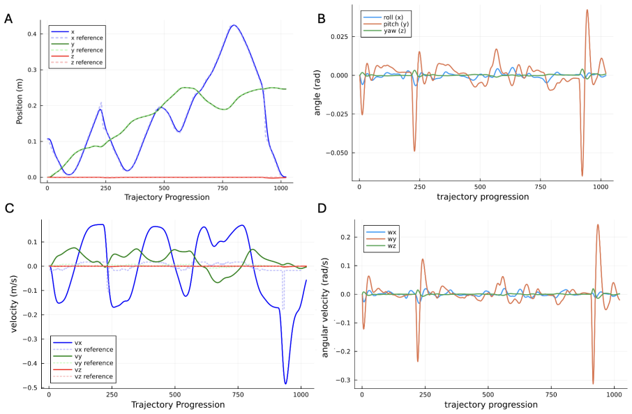
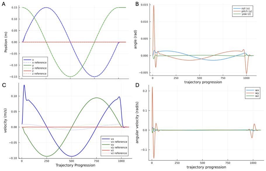
Magnasketch is an end-to-end system that lets a 33-gram Crazyflie 2.0 quadrotor with a 3D-printed, Z-compliant magnetic stylus draw images and text on a magnetic board. The central discovery claimed is that a convex MPC linearized about hover, augmented with two contact terms — a constant downward 2 N magnet force and a Coulomb friction force opposing marker slide — produces reference trajectories that, when tracked by the low-level full-state commander, yield drawings that are visually smoother than those of the stock high-level position commander, with average errors of 3.9 cm, 4.4 cm, and 0.5 cm in x, y, and z. The authors also show the optimizer generalizes across differentiable (figure-8, circle) and non-differentiable (cloud, cat, cursive text) inputs by changing only the horizon length and waypoint density, and that including the magnet dynamics reduces tracking error compared with the same MPC run without them.
Load-bearing premise
The load-bearing premise is that the magnet always pulls straight down on the board with a constant 2 N force and that the only sliding resistance is friction equal to the drone's weight times a coefficient, independent of gap, tilt, or actual normal force.
Editorial extensions
If this is right
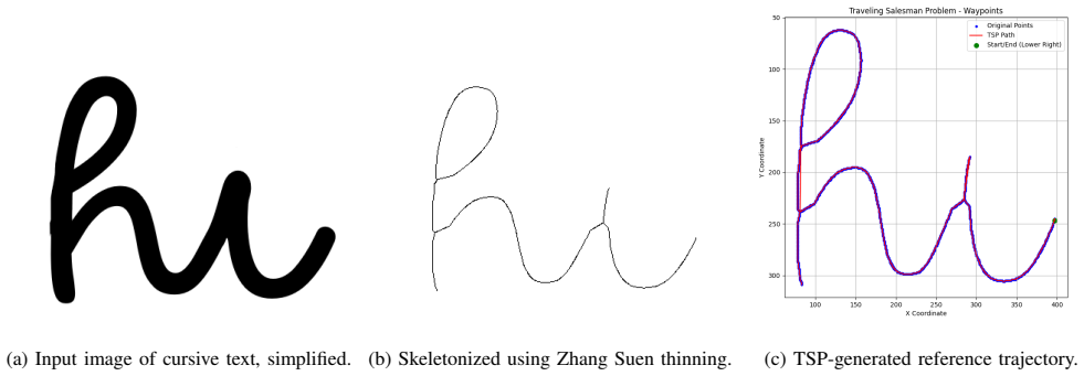
- Any image or text reducible to waypoints, including sharp-cornered non-differentiable strokes, can be turned into a dynamically feasible full-state trajectory for the Crazyflie by adjusting only the MPC horizon and waypoint spacing.
- Feeding full-state references to the low-level commander achieves drawing quality comparable to the stock position commander while exposing attitude, velocity, and angular-rate control for future manipulation tasks.
- Including the approximate magnet and friction terms in the model lowers tracking error relative to an identical MPC that omits them, and makes the generated motion physically meaningful at contact.
- Because the full pipeline runs on an open-source, roughly 33-gram platform with one 3D-printed part, contact-aided aerial drawing does not require heavy custom drones or costly online trajectory optimization.
Reading between the lines
- If the constant 2 N magnet force were replaced with a gap- and tilt-dependent force model, the same MPC framework would likely reduce z-error further; a force-sensor sweep would reveal whether the current benefit comes from the constant term or from the friction term.
- The observed smoothness gain may come as much from feeding full state references to the low-level controller as from the contact dynamics; zeroing the magnet terms while keeping the full-state trajectory would separate the two effects.
- The same hover-linearized, convex MPC with an added constant external force could transfer to other contact tasks, such as light pressing, cleaning, or writing on vertical surfaces with a compliant end-effector.
Editorial analysis
A structured set of objections, weighed in public.
Referee Report
Summary. The paper presents Magnasketch, a system that uses a Bitcraze Crazyflie 2.0 quadrotor to draw images on a magnetic board. User-supplied drawings are converted into waypoints, then into full-state trajectories by an offline convex MPC formulation that includes a simplified model of the magnet-board interaction (a constant downward force and Coulomb friction). The trajectories are executed through the Bitcraze Low-Level Commander, with the stock Position High-Level Commander used for takeoff, landing, and frame establishment. Hardware experiments compare three controllers—HL Commander, LL Commander without magnet dynamics, and LL Commander with magnet dynamics—on figure-8, circle, and cloud trajectories. The authors report average errors of 3.9 cm, 4.4 cm, and 0.5 cm in x, y, z for the magnet-dynamics controller and claim it achieves 'comparable performance' to the HL Commander while producing visually smoother drawings and offering full-state control.
Significance. If the stated comparative claims were fully supported, this would be a valuable low-cost, open-source demonstration of contact-aware drone drawing with full-state MPC, extending prior stippling and calligraphy work. The hardware demo is real and reproducible—code and sample drawings are linked in the appendix—and the compliant magnetic payload is a useful contribution. However, the significance currently rests on claims that are not yet established: the error gaps in Table II are substantial and untested, 'smoother' is only qualitatively assessed, and the benefit of the magnet-dynamics model is inconsistent across axes in the aggregate data. The contribution would be better framed as a feasibility demonstration with a clearly documented performance trade-off, pending additional evaluation.
major comments (4)
- [VIII, Abstract, Table II] The central claim of 'comparable performance' is not supported by the reported data. Table II gives mean absolute errors of 3.95 cm (x) and 4.43 cm (y) for the MPC+LL with magnet dynamics versus 2.79 cm and 2.91 cm for HL Commander, a 41% and 52% increase respectively, with no statistical tests, confidence intervals, or repeated trials (the reported standard deviations are across the three shapes, not across independent runs). Furthermore, Section VI shows the HL baseline tracked only waypoints at a fixed 0.075 m/s velocity while the LL controllers tracked the full MPC-generated state trajectory, so the error metrics are not measuring the same quantity. Please either define an explicit tolerance for 'comparable,' report per-run statistics, or reframe the claim as a trade-off rather than comparable performance.
- [VII-A, Tables II and III] Section VII-A states that including magnet dynamics 'improved the results significantly, both in terms of x-, y-, z- error,' citing Table III for figure-8. While that is true for figure-8 (x: 4.93 to 4.29, y: 5.90 to 5.72, z: 0.81 to 0.47), the aggregate data in Table II show the y-error increasing from 4.32 to 4.43 cm when magnet dynamics are added, so the improvement is not consistent across trajectories. The paper should either report per-shape errors with significance testing or temper the claim to specify that the improvement is observed only in some trajectories/axes.
- [VII-A, Figs. 17-18, 26-28] The claimed advantage of 'smoother, more aesthetically pleasing drawings' is supported only by visual inspection of Figures 17-18 and 26-28. No quantitative smoothness metric (e.g., curvature, jerk, or acceleration variation) or blinded human evaluation is provided. Because this is one of the two stated advantages over the baseline, the paper should either provide a measurable smoothness criterion or explicitly present this as a qualitative observation in the conclusions.
- [III-C, Eqs. (4)-(5)] The contact model assumes a constant downward magnet force of 2 N and Coulomb friction μmg sign(v) with the drone always perpendicular to the board. These assumptions are acknowledged but never validated against measurements of the actual force-versus-gap relationship or orientation dependence. Since 'newly incorporating magnetic force dynamics' is a stated contribution, the paper should provide at least basic validation—for example, a measured force-vs-gap curve for the magnet or a comparison of predicted versus actual tracking—to show that the model captures the dominant physics rather than acting as a fitted constant.
minor comments (5)
- [Abstract] The abstract contains a typographical error: 'UA Vs' should be 'UAVs'.
- [III-C, Eq. (5)] Equation (5) applies sign(v) to a vector quantity; please clarify whether this is an element-wise sign or a direction-dependent model, and specify the components.
- [III-C, Eq. (10)] The yaw torque equation appears to multiply a row vector by a 4x4 matrix, which is dimensionally inconsistent; please verify the notation and dimensions.
- [IV-D] The description of the velocity profile methods would benefit from a formal definition of 'inverse curvature' and how it was computed, since the current text relies on an intuitive understanding.
- [Table I, Ref. [9]] Reference [9] (TinyMPC) is cited as the source for model parameters, but TinyMPC is a controller library; please clarify the connection or provide the actual parameter source.
Circularity Check
No significant circularity; the derivation chain is a controller-design pipeline whose claims are validated by hardware experiments, not by reuse of its own outputs.
full rationale
This paper does not claim to derive a new physical prediction from first principles; it builds a trajectory-optimization pipeline and validates it by hardware comparison. The MPC cost (Section IV-E2) penalizes deviation of the generated trajectory from the user's waypoints, so the simulation's small tracking error is the optimization objective, not an independent prediction, and the paper does not present it as evidence of model correctness. The improved performance attributed to magnet dynamics is an experimental comparison between controllers (Tables II and III), not a deduction from the magnet model, so it cannot be circular. The 1 cm maximum deviation used in the Q weighting is a design constraint that explains the bounded simulation error; it is not a fitted parameter later renamed as a result. References are to external tools and prior drone-art work; no load-bearing self-citation or imported uniqueness theorem appears, and no central premise reduces to the paper's own conclusion by construction. Concerns about 'comparable' being undefined, the significance of the error gaps, and smoothness being unquantified are shortcomings in evidence quality and falsifiability, not circularity.
Assumptions & free parameters
free parameters (7)
- Magnet force magnitude =
constant -2 N in z
- Sliding friction coefficient =
not stated
- Maximum trajectory velocity =
0.01 m/s
- Z-offset correction =
about 1.8 cm above board plus per-trajectory tuning
- Contact settling time =
1.75 s
- Takeoff velocity =
0.5 m/s
- MPC cost weights =
position max deviation 0.01 m, velocity max deviation 0.5 m/s
assumptions (6)
- standard math Newton-Euler rigid-body dynamics and quaternion kinematics describe the Crazyflie.
- domain assumption A single linearization about hover is valid for the drawing task.
- ad hoc to paper Magnet force is constant, downward, and independent of distance and orientation.
- domain assumption Friction is Coulomb sliding friction and the drone stays perpendicular to the board.
- domain assumption Propeller airflow and turbulence are negligible.
- domain assumption The magnet payload moves rigidly with the drone.
Cite this review
Pith. "Pith review of Magnisketch Drone Control." pith.science (2026). https://pith.science/paper/WIFJJDGR
@misc{pith2026241210670,
  author       = {Pith},
  title        = {Pith review of: Magnisketch Drone Control},
  year         = {2026},
  howpublished = {\url{https://pith.science/paper/WIFJJDGR}},
  note         = {Machine review of arXiv:2412.10670}
}
read the original abstract
The use of Unmanned Aerial Vehicles (UAVs) for aerial tasks and environmental manipulation is increasingly desired. This can be demonstrated via art tasks. This paper presents the development of Magnasketch, capable of translating image inputs into art on a magnetic drawing board via a Bitcraze Crazyflie 2.0 quadrotor. Optimal trajectories were generated using a Model Predictive Control (MPC) formulation newly incorporating magnetic force dynamics. A Z-compliant magnetic drawing apparatus was designed for the quadrotor. Experimental results of the novel controller tested against the existing Position High Level Commander showed comparable performance. Although slightly outperformed in terms of error, with average errors of 3.9 cm, 4.4 cm, and 0.5 cm in x, y, and z respectively, the Magnasketch controller produced smoother drawings with the added benefit of full state control.
Figures


Figures from the paper (21 more)








Reference graph
Works this paper leans on
-
[1]
11em plus .33em minus .07em 4000 4000 100 4000 4000 500 `\.=1000 = #1 \@IEEEnotcompsoconly \@IEEEcompsoconly #1 * [1] 0pt [0pt][0pt] #1 * [1] 0pt [0pt][0pt] #1 * \| ** #1 \@IEEEauthorblockNstyle \@IEEEcompsocnotconfonly \@IEEEauthorblockAstyle \@IEEEcompsocnotconfonly \@IEEEcompsocconfonly \@IEEEauthordefaulttextstyle \@IEEEcompsocnotconfonly \@IEEEauthor...
- [2]
-
[3]
X. Guo, G. He, J. Xu, M. Mousaei, J. Geng, S. Scherer, and G. Shi, ``Flying calligrapher: Contact-aware motion and force planning and control for aerial manipulation,'' arXiv preprint arXiv:2407.05587, 2024
work page Pith review arXiv 2024
-
[4]
Bitcraze , ``Lighthouse painting with the crazyflie,'' https://www.bitcraze.io/2019/03/lighthouse-painting/, 2019, accessed: 2024-12-13
work page 2019
-
[5]
A. Uryasheva, M. Kulbeda, N. Rodichenko, and D. Tsetserukou, ``Dronegraffiti: autonomous multi-uav spray painting,'' in ACM SIGGRAPH 2019 Studio, ser. SIGGRAPH '19. 1em plus 0.5em minus 0.4em New York, NY, USA: Association for Computing Machinery, 2019. [Online]. Available: https://doi.org/10.1145/3306306.3328000
-
[6]
A. S. Vempati, M. Kamel, N. Stilinovic, Q. Zhang, D. Reusser, I. Sa, J. Nieto, R. Siegwart, and P. Beardsley, ``Paintcopter: An autonomous uav for spray painting on three-dimensional surfaces,'' IEEE Robotics and Automation Letters, vol. 3, no. 4, pp. 2862--2869, 2018
work page 2018
-
[7]
B. E. Jackson, K. Tracy, and Z. Manchester, ``Planning with Attitude .''
-
[8]
Aufrichtig, ``Coordinator,'' https://github.com/spotify/coordinator, 2021, accessed: 2024-10-11
A. Aufrichtig, ``Coordinator,'' https://github.com/spotify/coordinator, 2021, accessed: 2024-10-11
work page 2021
Show all 10 references
-
[9]
The Noun Project , ``The noun project: Icons for everything,'' https://thenounproject.com/, 2024, accessed: 2024-10-11
2024
-
[10]
Alavilli, K
A. Alavilli, K. Nguyen, S. Schoedel, B. Plancher, and Z. Manchester, `` TinyMPC : Model-Predictive Control on Resource-Constrained Microcontrollers ,'' in International Conference on Robotics and Automation ( ICRA ) . 1em plus 0.5em minus 0.4em Yokohama, Japan: arXiv, 2024
2024
Reviewed August 11, 2026 · model on record in the stance chip above.
Discussion (0). Continue with ORCID to comment.