REVIEW 3 major objections 4 minor 1 cited by
Bidirectional microwave-optical conversion with an integrated soft-ferroelectric barium titanate transducer
T0 review · 3 major / 4 minor · reviewed 2026-08-10 · deepseek-v4-flash
Pith's one-line read This paper demonstrates an integrated barium titanate transducer that converts microwave and optical photons bidirectionally at millikelvin temperatures.
desk verdict First integrated BaTiO3 microwave-optical transducer with honest, calibration-limited efficiency numbers; the platform work is solid and the absolute efficiency is openly flagged as approximate. read the letter →
The pith
A machine-rendered reading of the paper's core claim, the machinery that carries it, and where it could break.
The reading
What carries the argument
The load-bearing object is the triply resonant cavity electro-optic system: a photonic molecule formed by two evanescently coupled BaTiO3 ring resonators, whose antisymmetric optical beating is phase-matched to the field of a half-wavelength superconducting niobium microwave resonator. The interaction is the Pockels-effect Hamiltonian $H_{\mathrm{int}} = \hbar g_0 (a_+^\dagger a_- + a_-^\dagger a_+)(b + b^\dagger)$, with vacuum coupling $g_0 = G V_{\mathrm{zpf}}$, where $G = \partial \omega_a/\partial V$ is the frequency-pulling factor and $V_{\mathrm{zpf}}$ is the zero-point voltage across the ring capacitors. A dc-bias port placed at the voltage node of the microwave mode provides in-situ ferroelectric poling without adding microwave loss, and a capacitively coupled tuning electrode is part of the microwave resonator, giving 91% electrode coverage. The transduction response is modeled by a linearized input-output S-matrix that includes forward-backward optical scattering, and the efficiency is calibrated through a chain of separately measured optical, microwave, and heterodyne gains.
What would settle it
Measuring microwave-to-optical transduction in transmission at 10 mK with both optical fibers coupled, and comparing that directly measured efficiency with the reflection-corrected value of $1\times10^{-6}$, would settle whether the backscattering and calibration model is accurate.
Extended reading notes
Core claim
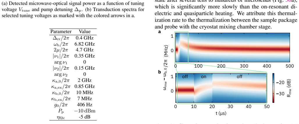
The central claim is a working, integrated, triply resonant electro-optic transducer in which a photonic molecule of two evanescently coupled BaTiO3 ring resonators is driven by a $\lambda/2$-type superconducting niobium microwave resonator, with the microwave frequency matched to the optical mode splitting. Bidirectional continuous-wave and pulsed transduction is demonstrated, with a peak pulsed off-chip efficiency of $1\times10^{-6}$ at 8 mK and linear behavior over a wide range of pump powers. The design places the dc-bias port at the voltage node of the microwave mode, so the ferroelectric can be poled in situ without loading the microwave circuit, and it capacitively couples the tuning electrode into the resonator to reach a usable electrode coverage of 91%. From the measured electro-optic tuning the authors extract a vacuum coupling rate $g_0/2\pi = 406$ Hz, corresponding to an effective Pockels coefficient of about 13 pm/V, more than an order of magnitude below the 200 pm/V reported for BaTiO3 thin films at cryogenic temperature. The paper also claims that optically induced heating in the quantum-relevant low-power regime is dominated by fast in-cavity dielectric heating rather than straylight-driven quasiparticle heating.
Load-bearing premise
The reported absolute efficiency of $1\times10^{-6}$ and the extracted coupling rate $g_0$ rest on a chain of calibration factors measured at room temperature, including an estimated $-5$ dB fiber-to-chip loss and empirical $+11.3$ dB and $+15.65$ dB power calibrations, and on a fitted backscattering model used because one optical fiber broke before the cryogenic run.
Editorial extensions
If this is right
- If the cryogenic Pockels coefficient can be raised from the measured 13 pm/V to the 200 pm/V reported for BaTiO3 films, the transduction efficiency would rise by roughly 20 dB.
- Improving the intrinsic optical quality factor from $1\times10^5$ to the reported absorption-limited $3.8\times10^6$ would add about 30 dB of efficiency, and the authors estimate that combining all listed improvements could bring off-chip efficiency close to unity.
- In the low-power regime relevant to quantum transduction, in-cavity dielectric heating dominates over quasiparticle heating, and its sub-microsecond response means it cannot be suppressed by lowering the optical pump duty cycle.
- The transducer design and the subtractive fabrication process transfer to other large-Pockels materials such as SrTiO3 and LiNbO3 with minor modifications.
- Optical-to-microwave transduction remains linear in pump power from $-30$ dBm to $+12$ dBm, and the phase-coherent interference of the two optical sidebands confirms that the conversion process is coherent.
Reading between the lines
- Beyond the paper: if the reduced 13 pm/V Pockels coefficient is indeed strain-related, cryogenic strain engineering of the BaTiO3 film is a direct, testable route to recover the 200 pm/V value, which would make the device competitive with optimized LiNbO3 transducers at much lower pump power.
- Beyond the paper: because the microwave-to-optical path was measured through residual backscattering with one fiber broken, the true on-chip microwave-to-optical efficiency could be higher than the reported off-chip value; a fully packaged two-fiber measurement would separate device efficiency from the backscattering correction.
- Beyond the paper: the post-cooldown inversion of the optical tuning polarity suggests that cooling under an applied bias may deterministically set the ferroelectric domain orientation, which could be used as a fabrication protocol to maximize the low-temperature Pockels response.
- Beyond the paper: the demonstrated linear transduction range and the identified heating budget imply that added-noise measurements at single-photon levels are the next decisive test; the paper's estimate of about three photons of added noise at 0 dBm peak pump power could be verified directly with a calibrated noise measurement.
Editorial analysis
A structured set of objections, weighed in public.
Referee Report
Summary. The manuscript presents an integrated microwave-optical transducer based on BaTiO3-on-SiO2, consisting of a photonic molecule (two coupled ring resonators) and a superconducting Nb microwave resonator. The authors demonstrate bidirectional continuous-wave and pulsed transduction with an off-chip efficiency of 1×10⁻⁶ at 8 mK, in-situ ferroelectric poling through a bias port located at the microwave voltage null, and a fully subtractive fabrication process with superconducting air bridges. They also study optically induced heating, distinguishing fast in-cavity dielectric heating from slower substrate and quasiparticle heating. The measured efficiencies are modeled with a linearized input-output S-matrix theory (Appendix B) using parameters from independent characterizations, including a g0 = 2π×406 Hz obtained from dc electro-optic tuning.
Significance. If the claims hold, this is the first integrated triply resonant electro-optic transducer using a soft ferroelectric (BaTiO3), demonstrating a viable path toward higher-Pockels-coefficient materials for quantum interconnects. The in-situ poling concept and the subtractive air-bridge fabrication are genuinely useful contributions that transfer to other ferroelectrics. The paper is strengthened by a self-contained S-matrix model, an independent dc-tuning extraction of g0 (Appendix E2), and a careful thermal characterization with a physically motivated line-shape model. However, the quantitative headline (1e-6 off-chip efficiency) rests on a room-temperature fiber-coupling calibration and an empirical power calibration chain, and the measured device was operated with a ~2 GHz detuning from the nominal triple-resonance condition. These limitations are acknowledged in the body but not fully reflected in the abstract.
major comments (3)
- [Sec. IV / App. D2 / Fig. 5c] The absolute off-chip efficiencies plotted in Fig. 5c are obtained via a calibration chain (Appendix D2) that includes a fiber-to-chip loss 'estimated at −5 dB from room-temperature characterization' and two empirical factors (+11.3 dB and +15.65 dB). The only cryogenic cross-check is the cw optical-heating comparison in Appendix D2, which calibrates power in the fiber but not the fiber-to-chip interface itself. Section VI reports a sudden, irreversible degradation of the fiber-chip efficiency under high optical power, demonstrating that the interface is not stable under the operating conditions used in this work. Because the headline efficiency of 1×10⁻⁶ and the comparison to state-of-the-art LiNbO3 transducers in Fig. 5c are directly proportional to these calibration factors, a systematic drift of even 3–5 dB would change the central quantitative claim by a comparable factor. I request an uncertainty budget for the reported efficiencies, and either a cryogenic calibration of the fiber-to-chip loss or a clear statement that the quoted efficiencies are upper bounds based on room-temperature coupling estimates.
- [Sec. IV / App. B2] The microwave-to-optical direction was measured entirely in reflection after one optical fiber broke (Sec. III), relying on 'residual optical backscattering' for signal extraction (Sec. IV). The transduction efficiency for this direction is modeled with fitted forward-backward coupling rates ν1,2 (Appendix B2, Table V). The authors themselves state that intra-ring backscattering cannot be clearly distinguished from residual backscattering at the bus-waveguide end facet. Consequently, the absolute efficiency of the microwave-to-optical path and the >10 dB asymmetry between the two directions depend on an ambiguous model parameter. This does not affect the optical-to-microwave efficiency, but the bidirectional quantitative comparison should be presented with this caveat, and the abstract's unqualified 'bidirectional' efficiency should be limited to the optical-to-microwave direction or explicitly qualified.
- [Sec. III, IV, G] The paper repeatedly describes the device as 'triply resonant', but the measured photonic-molecule splitting is 2µ = 2π×4.7 GHz (Sec. III) while the microwave resonance is at ωb = 2π×6.82 GHz (Sec. III); the residual detuning of ~2.1 GHz is acknowledged in Sec. G as the likely cause of the central-peak splitting. The transduction data in Fig. 3 were therefore taken with the microwave-to-molecule frequency mismatch present, and the authors list 'eliminat[ing] the mismatch... providing another 4 dB improvement' as a future improvement (Sec. VII). The abstract and introduction's 'triply resonant transducer' overstates the as-measured device. Please qualify the abstract (e.g., 'designed to be triply resonant') and quantify the detuning in the main text and figures.
minor comments (4)
- [App. E2 / A4] The g0 value used in the consistency check combines a measured dc tuning slope with a simulated zero-point voltage; please state the systematic uncertainty in g0 and explicitly note that the dc Pockels response is an upper bound for the microwave-frequency response, as the text already suggests.
- [Data Availability] The Data Availability statement says 'available through Zenodo at (to be provided)'; this must be completed before publication.
- [Sec. IV / Fig. 3] The notation ω+ and ω− is ambiguous: Section IV calls the resonance with ∆p=0 the 'lower photonic molecule resonance' while Fig. 3c assigns Stokes and anti-Stokes peaks to opposite detunings; please define the mode ordering explicitly.
- [Sec. VI] The sentence 'with increasing pump power the pulse length is decreased from 1 ms to 40 µs' mixes present and past tense; also verify the stated duty-cycle arithmetic for a fixed 0.8 kHz repetition rate.
Circularity Check
Headline efficiency is a direct calibrated measurement; only a minor fitted-backscattering explanation is circular, and the g0 consistency check is independent.
-
fitted input called prediction
[Section IV, paragraph beginning 'To understand the electro-optic response of the device' (transduction model discussion)]
"We find that the reduced microwave-to-optical transduction efficiency of the signal emitted in the backward direction is well explained by a low forward-backward coupling strength of ν1,2 ≈ 0.1κa."
In the preceding paragraph the theory curves are generated by 'adjusting the photonic-molecule coupling strength µ, the ring-resonator detuning ∆rr, the optical loss rates, as well as the coherent optical forward-backward coupling rates ν1,2.' The reduced microwave-to-optical efficiency is part of the same dataset used to fit ν1,2, so saying it is 'well explained' by the fitted ν1,2 restates the fit rather than providing an independent prediction. The authors acknowledge the ambiguity with residual end-facet backscattering. This step is peripheral: the absolute efficiency and the independent g0 consistency check do not reduce to this fitted parameter.
full rationale
The paper's central quantitative claim is a measured off-chip transduction efficiency, calibrated through the explicit chain of Appendix D2, not a derivation from a fitted model. The vacuum coupling rate g0 = 2π × 406 Hz used in the transduction model is extracted independently from dc electro-optic tuning (Appendix E2) and the microwave loss rates from independent spectroscopy, so the agreement between the measured efficiencies and the model is a genuine, non-circular consistency check rather than a parameter renamed as a prediction. The cited BaTiO3 Pockels coefficient of 200 pm/V [36] is an external experimental result; the overlap of one co-author (D. Caimi) with the present paper does not make it circular, and the paper's own measurement finds a much lower r = 13 pm/V, which would be impossible if the external value were simply assumed. No uniqueness theorem or load-bearing self-citation chain is invoked. The only identifiable circular element is a secondary interpretive statement: the reduced microwave-to-optical signal in the backward direction is attributed to the forward-backward coupling rate ν1,2, but that rate is itself one of the parameters fitted to the transduction spectra. Because this fit does not support the headline efficiency or the independent g0 consistency check, the overall circularity is minor. Other noted weaknesses, such as the fiber-to-chip loss estimated at room temperature and the reliance on residual backscattering after a fiber break, are calibration and systematic-error concerns, not circular reductions.
Assumptions & free parameters
free parameters (8)
- Effective Pockels coefficient r =
13 pm/V
- Photonic molecule coupling 2*mu/2*pi =
4.7 GHz
- Ring-ring detuning Delta_rr/2*pi =
0.4 GHz
- Forward-backward coupling rates |nu_1|/2*pi and |nu_2|/2*pi =
0.35 GHz and 0.15 GHz
- Optical loss rates kappa_a,0/2*pi and kappa_a,ex/2*pi =
2 GHz and 0.85 GHz
- TLS quality factor Q_b,0,TLS =
2038
- Kinetic inductance fraction alpha =
7.8%
- Microwave external and internal loss rates kappa_b,ex and kappa_b,0 =
7 MHz and 10 MHz
assumptions (5)
- standard math The electro-optic interaction is described by the Hamiltonian H_int = hbar*g0*(a_plus_dagger*a_minus + a_minus_dagger*a_plus)*(b + b_dagger) within the linearized input-output formalism.
- domain assumption The dc electro-optic tuning slope d(omega_a)/dV = 2*pi*145 MHz/V provides an upper bound for the microwave vacuum frequency-pulling factor G.
- ad hoc to paper The angular dependence of the Pockels coefficient in the ring follows a sinusoidal function with maxima every 90 degrees, reducing the effective overlap to alpha_overlap = 0.42.
- domain assumption The thermal shift of the microwave resonance is a sum of TLS and BCS quasiparticle contributions (Eqs. F1-F3).
- domain assumption The microwave extinction ratio during optical pumping can be calibrated as a proxy for a single effective temperature T_eff.
Cite this review
Pith. "Pith review of Bidirectional microwave-optical conversion with an integrated soft-ferroelectric barium titanate transducer." pith.science (2026). https://pith.science/paper/XVPDWD74
@misc{pith2026250109728,
  author       = {Pith},
  title        = {Pith review of: Bidirectional microwave-optical conversion with an integrated soft-ferroelectric barium titanate transducer},
  year         = {2026},
  howpublished = {\url{https://pith.science/paper/XVPDWD74}},
  note         = {Machine review of arXiv:2501.09728}
}
abstract
Efficient, low-noise, and high-bandwidth transduction between optical and microwave photons is key to long-range quantum communication between distant superconducting quantum processors. Recent demonstrations of microwave-optical transduction using the broadband direct electro-optic (Pockels) effect in optical thin films made of AlN or LiNbO$_3$ have shown promise. To improve efficiency and added noise, materials with larger Pockels coefficients, such as the soft ferroelectrics BaTiO$_3$ or SrTiO$_3$, are required. However, these materials require adapted designs and fabrication approaches due to their nonlinear and, in some cases, hysteretic electro-optic response. Here, we engineer an on-chip, triply resonant transducer comprising low-loss BaTiO$_3$-on-SiO$_2$ waveguides monolithically integrated with a superconducting microwave resonator made of Nb. We demonstrate bidirectional microwave-optical transduction and reach total off-chip efficiencies of $1\times10^{-6}$ using pulsed pumping. Our novel device concept permits in-situ poling of the ferroelectric material without introducing excess microwave loss, using a fully subtractive fabrication process with superconducting air bridges. In addition, we investigate optically induced heating, revealing fast thermalization and quasiparticle resilience of the microwave resonator. Our transducer concept and fabrication process are applicable to other materials with a large bias-induced Pockels effect and pave the way for efficient, low-power quantum interconnects.
Figures


Figures from the paper (22 more)


Forward citations
Cited by 1 Pith paper
-
Low loss monolithic barium titanate on insulator integrated photonics with intrinsic quality factor >1 million
Monolithic barium titanate microresonators with intrinsic quality factor above one million and waveguide loss of 0.32 dB/cm are demonstrated using a redeposition-free dry etch.
Reference graph
Works this paper leans on
-
[1]
The vacuum speed of light is c0 = 1 /√ϵ0µ0
Field quantization First, we recall that the classical electromagnetic energy density ρem is defined as the absolute value of the Poynting vector [56], ρem = 1 2 (E · D + H · B) , (A1) 12 with electric field E, electric displacement field D = ϵ0ϵrE, vacuum permittivity ϵ0, and relative permittivity ϵr; and mag- netic field H, magnetic flux density B = µ0µ...
-
[2]
Electro-optic interaction Hamiltonian Based on refs. [22–24], we first consider the optical electric energy density and express it in terms of the displacement field Di = ϵij r Ej, ρel,opt = 1 2 ϵ0Ei optϵij r,optEj opt (A15) = 1 2 ϵ0Di opt ϵ−1 r,opt ij Dj opt. (A16) Here and in what follows, it is implicit that indices appearing twice are summed over. We ...
-
[3]
Separating longitudinal and cross-sectional integration Since the overlap only happens in the active material of the optical rings, we can separate the integration into a longitudi- nal (dz) and cross sectional part (dxdy). For the longitudinal integral along one optical ring resonator with radiusR, we get (neglecting curvature) Z rdz = rαoverlapLopt (A24...
-
[4]
7a), which is computation- ally expensive
Microwave equivalent circuit An analogous normalization factor equation like (A28) holds for the microwave field as well, but requires simulating the whole microwave mode (Fig. 7a), which is computation- ally expensive. Instead, we only simulate the fraction of the microwave mode in the transducer electrode, and normalize it with the fraction of the energ...
-
[5]
We do this, by requiring a constant resonance frequency ωb of the transducer ωb = 1√ LC
Incorporating scaling with material permittivity In order to fairly compare the vacuum coupling strength of the same device design and cross-sectional geometry but for different active materials with similar optical properties but sometimes vastly different permittivities (ϵr,LiNbO3 = 30, ϵr,BaTiO3 = 2 × 10², ϵr,SrTiO3 ≈ 2 × 10⁴), we incorporate the scali...
-
[6]
We describe the system as a collection of resonant modes with annihilation operators Ai, resonance frequencies ωi, and internal loss rates κi,0
General picture In this section we give an introduction to the input-output formalism and coupled-mode theory to describe the linearized response of the cavity electro-optic system studied in this work. We describe the system as a collection of resonant modes with annihilation operators Ai, resonance frequencies ωi, and internal loss rates κi,0. Some of t...
-
[7]
As shown in Fig
Photonic molecule with forward-backward scattering First, we apply the formalism derived above to describe the coupled optical resonators in the transducer. As shown in Fig. 10b, the two ring resonators are coupled evanescently at rate µ, and resonator 1 is coupled to the optical bus waveguide at rate κ1,ex. Moreover, the fabricated waveguides exhibit im-...
-
[8]
Transduction model We now use the formalism from Sec. B 1 to describe the full transducer by including microwave resonator and the electro- optic interaction (Fig. 11). For clarity, we divide the sys- tem Hamiltonian into its optical, microwave, and electro-optic parts, i.e. H = Ha + Hb + Heo, (B20) with microwave Hamiltonian Hb = ℏωbb†b (B21) and the ele...
Show all 87 references
-
[9]
Microwave spurious mode coupling We now derive the linear response for the coupling between the microwave resonator and the spurious mode detailed in Sec. F. The system comprises two microwave resonatorsb and b2 with resonance frequencies ωb and ωb,2, and intrinsic loss rates ...
-
[10]
We start with a 225-nm thick BaTiO 3 thin film bonded on 3 µm of SiO 2 on silicon (Fig
Sample fabrication We have developed a process to fabricate low-loss, high- confinement photonic waveguides and resonators in BaTiO 3 and integrate them with Nb superconducting circuits. We start with a 225-nm thick BaTiO 3 thin film bonded on 3 µm of SiO 2 on silicon (Fig. 13...
-
[11]
The fiber is then glued to the chip facet and supsequently glued to the package further back with additional gluing points as shown in Fig
Packaging In- and output high numerical aperture fibers (UHNA7, mode-field diameter 3.2 µm) are first aligned to the chip by optimizing the optical transmission through the bus waveg- uide. The fiber is then glued to the chip facet and supsequently glued to the package further...
-
[12]
Cryostat wiring The wiring inside the cryostat is shown in Fig. 16. Our cryostat (BlueFors LD400) features a fast sample exchange bottom probe mechanism. While the electrical signals are de- livered from the top of the cryostat at the cryostat breakout connectors (fridge BO), ...
-
[13]
Chu and S
Y . Chu and S. Gröblacher, A perspective on hybrid quantum opto- and electromechanical systems, Appl. Phys. Lett. 117, 150503 (2020)
2020
-
[14]
Calibration of transduction efficiency The optical input power arriving at the fiber inside the probe is calibrated by comparing cw optical heating of the cryostat to that using the resistive probe heater, from which the fac- tor +11.3 dB between the TLPM_dev_in power meter re...
-
[15]
Pulsed microwave characterization To characterize the microwave reflection under pulsed opti- cal pumping, we use a setup very similar to the pulsed trans- duction setup. The main difference is, that only the pump laser is sent to the device, and instead of measuring the trans...
-
[16]
Continuous wave transduction The setup for continuous wave and bidirectional transduc- tion measurements is shown in Fig. 18. Two continuously tunable external-cavity diode lasers (Laser 1 and 2) are used for optical pumping and probing. The main and pump laser in 23 TLPM_dev_...
-
[17]
The setup is shown in Fig
Pulsed transduction For studying the system in pulsed operation, we only per- form optical-to-microwave transduction using two lasers with an offset lock, as the signal is less sensitive to variations in the optical reflection from the device compared to the microwave- to-opti...
-
[18]
Room temperature transmission before cooldown In this section, the optical response of the device is stud- ied in transmission at room temperature before cooldown, as shown in Fig. 20. The transmission coefficient in this case is defined as T = |aout,cc/ain,cc|2. Note, that fo...
-
[19]
Cryogenic temperature optical tuning Next, we extract the resonance frequency ωa of the pho- tonic molecule as a function of bias voltage in the linear range close to the standard working point of Vbias = −100 V (Fig. 22). We then fit a linear function to the trend, and ex- tr...
-
[20]
Interestingly, the re- sponse (Fig
Room temperature optical transmission after warm-up Since no voltages were applied to the transducer device prior to cooling down the sample, we characterize the sam- ple post-cooldown at room temperature. Interestingly, the re- sponse (Fig. 23) looks vastly different to the e...
-
[21]
While only one device (device 2) is fully packaged, we wired up a reference device (device 6) for microwave characterization
Bias dependence Analogously to the characterization of the optical response as a function of bias voltage, we now study the microwave reflection with applied bias. While only one device (device 2) is fully packaged, we wired up a reference device (device 6) for microwave chara...
-
[22]
Typically however, the sig- nal levels in transducers for quantum transduction are just a few or even single photons
Microwave power dependence So far, we have been probing the microwave system in the medium to high power regime. Typically however, the sig- nal levels in transducers for quantum transduction are just a few or even single photons. In this low power regime, ab- sorption from tw...
-
[23]
Note, that this means that both the bottom probe and mixing chamber temperature are swept simultaneously, which we call Tfridge
Temperature dependence In this section, we sweep the temperature of the cryo- stat ("fridge") by either evaporating the helium cooling mix- ture (warm up) or recondensing it (cool down) while simul- taneously measuring the microwave reflection at high probe power. Note, that t...
-
[24]
Grumbling and M
Committee on Technical Assessment of the Feasibility and Implications of Quantum Computing, Computer Science and Telecommunications Board, Intelligence Community Studies Board, Division on Engineering and Physical Sciences, and National Academies of Sciences, Engineering, and ...
2019
-
[25]
Bravyi, O
S. Bravyi, O. Dial, J. M. Gambetta, D. Gil, and Z. Nazario, The future of quantum computing with superconducting qubits, Journal of Applied Physics 132, 160902 (2022)
2022
-
[26]
Storz, J
S. Storz, J. Schär, A. Kulikov, P. Magnard, P. Kurpiers, J. Lü- tolf, T. Walter, A. Copetudo, K. Reuer, A. Akin, J.-C. Besse, M. Gabureac, G. J. Norris, A. Rosario, F. Martin, J. Martinez, W. Amaya, M. W. Mitchell, C. Abellan, J.-D. Bancal, N. San- gouard, B. Royer, A. Blais, ...
2023
-
[27]
A. J. Stolk, K. L. van der Enden, M.-C. Slater, I. te Raa-Derckx, P. Botma, J. van Rantwijk, J. J. B. Biemond, R. A. J. Hagen, R. W. Herfst, W. D. Koek, A. J. H. Meskers, R. V ollmer, E. J. van Zwet, M. Markham, A. M. Edmonds, J. F. Geus, F. Elsen, B. Jungbluth, C. Haefner, C....
2024
-
[28]
A second standard splice between two SMF-28 fibers connects the cryostat fiber to the fiber connector (FC)
using a hybrid splicing program that creates a smooth tran- sition between the two (hsplice), with typical losses on the or- der of −1 dB. A second standard splice between two SMF-28 fibers connects the cryostat fiber to the fiber connector (FC)
-
[29]
Liu, X.-Y
J.-L. Liu, X.-Y . Luo, Y . Yu, C.-Y . Wang, B. Wang, Y . Hu, J. Li, M.-Y . Zheng, B. Yao, Z. Yan, D. Teng, J.-W. Jiang, X.-B. Liu, X.-P. Xie, J. Zhang, Q.-H. Mao, X. Jiang, Q. Zhang, X.-H. Bao, and J.-W. Pan, Creation of memory-memory entanglement in a metropolitan quantum net...
2024
-
[30]
J.-G. Ren, P. Xu, H.-L. Yong, L. Zhang, S.-K. Liao, J. Yin, W.-Y . Liu, W.-Q. Cai, M. Yang, L. Li, K.-X. Yang, X. Han, Y .-Q. Yao, J. Li, H.-Y . Wu, S. Wan, L. Liu, D.-Q. Liu, Y .-W. Kuang, Z.-P. He, P. Shang, C. Guo, R.-H. Zheng, K. Tian, Z.- 30 C. Zhu, N.-L. Liu, C.-Y . Lu, ...
2017
-
[31]
Huang, F
Y . Huang, F. Salces–Carcoba, R. X. Adhikari, A. H. Safavi- Naeini, and L. Jiang, Vacuum Beam Guide for Large Scale Quantum Networks, Phys. Rev. Lett. 133, 020801 (2024)
2024
-
[32]
Lago-Rivera, S
D. Lago-Rivera, S. Grandi, J. V . Rakonjac, A. Seri, and H. de Riedmatten, Telecom-heralded entanglement between multimode solid-state quantum memories, Nature 594, 37 (2021), publisher: Nature Publishing Group
2021
-
[33]
van Leent, M
T. van Leent, M. Bock, F. Fertig, R. Garthoff, S. Eppelt, Y . Zhou, P. Malik, M. Seubert, T. Bauer, W. Rosenfeld, W. Zhang, C. Becher, and H. Weinfurter, Entangling single atoms over 33 km telecom fibre, Nature 607, 69 (2022), pub- lisher: Nature Publishing Group
2022
-
[34]
C. M. Knaut, A. Suleymanzade, Y .-C. Wei, D. R. Assump- cao, P.-J. Stas, Y . Q. Huan, B. Machielse, E. N. Knall, M. Su- tula, G. Baranes, N. Sinclair, C. De-Eknamkul, D. S. Levonian, M. K. Bhaskar, H. Park, M. Lon ˇcar, and M. D. Lukin, Entan- glement of nanophotonic quantum m...
2024
-
[35]
H. J. Kimble, The quantum internet, Nature 453, 1023 (2008), number: 7198 Publisher: Nature Publishing Group
2008
-
[36]
Wehner, D
S. Wehner, D. Elkouss, and R. Hanson, Quantum internet: A vision for the road ahead, Science 362, eaam9288 (2018), pub- lisher: American Association for the Advancement of Science
2018
-
[37]
N. Lauk, N. Sinclair, S. Barzanjeh, J. P. Covey, M. Saffman, M. Spiropulu, and C. Simon, Perspectives on quantum trans- duction, Quantum Sci. Technol. 5, 020501 (2020)
2020
-
[38]
Krastanov, H
S. Krastanov, H. Raniwala, J. Holzgrafe, K. Jacobs, M. Lonˇcar, M. J. Reagor, and D. R. Englund, Optically Heralded Entangle- ment of Superconducting Systems in Quantum Networks, Phys. Rev. Lett. 127, 040503 (2021)
2021
-
[39]
Mirhosseini, A
M. Mirhosseini, A. Sipahigil, M. Kalaee, and O. Painter, Superconducting qubit to optical photon transduction, Na- ture 588, 599 (2020), bandiera_abtest: a Cg_type: Na- ture Research Journals Number: 7839 Primary_atype: Re- search Publisher: Nature Publishing Group Subject_ter...
2020
-
[40]
S. Hönl, Y . Popoff, D. Caimi, A. Beccari, T. J. Kippenberg, and P. Seidler, Microwave-to-optical conversion with a gal- lium phosphide photonic crystal cavity, Nat Commun 13, 2065 (2022)
2022
-
[41]
Jiang, F
W. Jiang, F. M. Mayor, S. Malik, R. Van Laer, T. P. McKenna, R. N. Patel, J. D. Witmer, and A. H. Safavi-Naeini, Optically heralded microwave photon addition, Nat. Phys. , 1 (2023), pub- lisher: Nature Publishing Group
2023
-
[42]
M. J. Weaver, P. Duivestein, A. C. Bernasconi, S. Scharmer, M. Lemang, T. C. v. Thiel, F. Hijazi, B. Hensen, S. Gröblacher, and R. Stockill, An integrated microwave-to-optics interface for scalable quantum computing, Nat. Nanotechnol. 19, 166 (2024), publisher: Nature Publishing Group
2024
-
[43]
Meesala, D
S. Meesala, D. Lake, S. Wood, P. Chiappina, C. Zhong, A. D. Beyer, M. D. Shaw, L. Jiang, and O. Painter, Quantum En- tanglement between Optical and Microwave Photonic Qubits, Phys. Rev. X 14, 031055 (2024), publisher: American Physical Society
2024
-
[44]
H. Zhao, W. D. Chen, A. Kejriwal, and M. Mirhosseini, Quantum-enabled continuous microwave-to-optics frequency conversion (2024), arXiv:2406.02704 [physics, physics:quant- ph]
2024 arXiv
-
[45]
Fan, C.-L
L. Fan, C.-L. Zou, R. Cheng, X. Guo, X. Han, Z. Gong, S. Wang, and H. X. Tang, Superconducting cavity electro- optics: A platform for coherent photon conversion between superconducting and photonic circuits, Sci. Adv. 4, eaar4994 (2018)
2018
-
[46]
T. P. McKenna, J. D. Witmer, R. N. Patel, W. Jiang, R. Van Laer, P. Arrangoiz-Arriola, E. A. Wollack, J. F. Herrmann, and A. H. Safavi-Naeini, Cryogenic microwave-to-optical conversion us- ing a triply resonant lithium-niobate-on-sapphire transducer, Optica 7, 1737 (2020)
2020
-
[47]
Holzgrafe, N
J. Holzgrafe, N. Sinclair, D. Zhu, A. Shams-Ansari, M. Colan- gelo, Y . Hu, M. Zhang, K. K. Berggren, and M. Lon ˇcar, Cavity electro-optics in thin-film lithium niobate for efficient microwave-to-optical transduction, Optica 7, 1714 (2020)
2020
-
[48]
H. K. Warner, J. Holzgrafe, B. Yankelevich, D. Barton, S. Po- letto, C. J. Xin, N. Sinclair, D. Zhu, E. Sete, B. Langley, E. Bat- son, M. Colangelo, A. Shams-Ansari, G. Joe, K. K. Berggren, L. Jiang, M. Reagor, and M. Loncar, Coherent control of a su- perconducting qubit using...
2023 arXiv
-
[49]
R. Sahu, W. Hease, A. Rueda, G. Arnold, L. Qiu, and J. M. Fink, Quantum-enabled operation of a microwave-optical inter- face, Nat Commun 13, 1276 (2022)
2022
-
[50]
R. Sahu, L. Qiu, W. Hease, G. Arnold, Y . Minoguchi, P. Rabl, and J. M. Fink, Entangling microwaves with light, Science380, 718 (2023)
2023
-
[51]
Arnold, T
G. Arnold, T. Werner, R. Sahu, L. N. Kapoor, L. Qiu, and J. M. Fink, All-optical single-shot readout of a superconducting qubit (2023), arXiv:2310.16817 [quant-ph]
2023 arXiv
-
[52]
M. Shen, J. Xie, Y . Xu, S. Wang, R. Cheng, W. Fu, Y . Zhou, and H. X. Tang, Photonic link from single flux quantum cir- cuits to room temperature (2023), arXiv:2309.03284 [physics, physics:quant-ph]
2023 arXiv
-
[53]
W. Fu, M. Xu, X. Liu, C.-L. Zou, C. Zhong, X. Han, M. Shen, Y . Xu, R. Cheng, S. Wang, L. Jiang, and H. X. Tang, Cavity electro-optic circuit for microwave-to-optical conversion in the quantum ground state, Phys. Rev. A 103, 053504 (2021)
2021
-
[54]
Y . Xu, A. A. Sayem, L. Fan, C.-L. Zou, S. Wang, R. Cheng, W. Fu, L. Yang, M. Xu, and H. X. Tang, Bidirectional intercon- version of microwave and light with thin-film lithium niobate, Nat Commun 12, 4453 (2021)
2021
-
[55]
Y . Xu, W. Fu, Y . Zhou, M. Xu, M. Shen, A. A. Sayem, and H. X. Tang, Light-Induced Dynamic Frequency Shifting of Microwave Photons in a Superconducting Electro-Optic Con- verter, Phys. Rev. Appl. 18, 064045 (2022), publisher: Ameri- can Physical Society
2022
-
[56]
X. Zhu, Y . Hu, S. Lu, H. K. Warner, X. Li, Y . Song, L. Magal- hães, A. Shams-Ansari, A. Cordaro, N. Sinclair, and M. Lonˇcar, Twenty-nine million intrinsic Q -factor monolithic microres- onators on thin-film lithium niobate, Photon. Res. 12, A63 (2024)
2024
-
[57]
Hease, A
W. Hease, A. Rueda, R. Sahu, M. Wulf, G. Arnold, H. G. Schwefel, and J. M. Fink, Bidirectional Electro-Optic Wave- length Conversion in the Quantum Ground State, PRX Quan- tum 1, 020315 (2020)
2020
-
[58]
Y . Hu, M. Yu, B. Buscaino, N. Sinclair, D. Zhu, R. Cheng, A. Shams-Ansari, L. Shao, M. Zhang, J. M. Kahn, and M. Lon ˇcar, High-efficiency and broadband on-chip electro- optic frequency comb generators, Nat. Photon. 16, 679 (2022)
2022
-
[59]
Eltes, G
F. Eltes, G. E. Villarreal-Garcia, D. Caimi, H. Siegwart, A. A. Gentile, A. Hart, P. Stark, G. D. Marshall, M. G. Thompson, 31 J. Barreto, J. Fompeyrine, and S. Abel, An integrated optical modulator operating at cryogenic temperatures, Nat. Mater. 19, 1164 (2020)
2020
-
[60]
Anderson, G
C. Anderson, G. Scuri, A. White, D. Lukin, E. Szakiel, J. Yang, K. Van Gasse, M. Guidry, W. Jiang, A. Safavi-Naeini, and J. Vuckovic, Quantum critical electro-optic materials for pho- tonics, in CLEO 2023 (Optica Publishing Group, San Jose, CA,
2023
-
[61]
G. A. Smolenskii, N. N. Krainik, N. P. Khuchua, V . V . Zh- danova, and I. E. Mylnikova, The Curie Temperature of LiNbO 3, Physica Status Solidi (b) 13, 309 (1966)
1966
-
[62]
M. G. Harwood, P. Popper, and D. F. Rushman, Curie Point of Barium Titanate, Nature 160, 58 (1947)
1947
-
[63]
S. Abel, F. Eltes, J. E. Ortmann, A. Messner, P. Castera, T. Wag- ner, D. Urbonas, A. Rosa, A. M. Gutierrez, D. Tulli, P. Ma, B. Baeuerle, A. Josten, W. Heni, D. Caimi, L. Czornomaz, A. A. Demkov, J. Leuthold, P. Sanchis, and J. Fompeyrine, Large Pockels effect in micro- and n...
2019
-
[64]
K. A. Müller and H. Burkard, SrTi O 3 : An intrinsic quantum paraelectric below 4 K, Phys. Rev. B 19, 3593 (1979)
1979
-
[65]
Fujii and T
Y . Fujii and T. Sakudo, Interferometric Determination of the Quadratic Electro-Optic Coefficients in SrTiO3 Crystal, Journal of Applied Physics 41, 4118 (2003)
2003
-
[66]
K. D. Fredrickson, V . V . V ogler-Neuling, K. J. Kormondy, D. Caimi, F. Eltes, M. Sousa, J. Fompeyrine, S. Abel, and A. A. Demkov, Strain enhancement of the electro-optical response in BaTi O 3 films integrated on Si ( 001 ), Phys. Rev. B98, 075136 (2018)
2018
-
[67]
H. Tian, J. Liu, A. Attanasio, A. Siddharth, T. Blésin, R. Ning Wang, A. V oloshin, G. Lihachev, J. Riemensberger, S. E. Kenning, Y . Tian, T. Han Chang, A. Bancora, V . Snigirev, V . Shadymov, T. J. Kippenberg, and S. A. Bhave, Piezoelectric actuation for integrated photonics...
2024
-
[68]
A. K. Hamze, M. Reynaud, J. Geler-Kremer, and A. A. Demkov, Design rules for strong electro-optic materials, npj Comput Mater 6, 130 (2020)
2020
-
[69]
R. Xu, J. Huang, E. S. Barnard, S. S. Hong, P. Singh, E. K. Wong, T. Jansen, V . Harbola, J. Xiao, B. Y . Wang, S. Cross- ley, D. Lu, S. Liu, and H. Y . Hwang, Strain-induced room- temperature ferroelectricity in SrTiO3 membranes, Nat Com- mun 11, 3141 (2020)
2020
-
[70]
M. Xu, C. Li, Y . Xu, and H. X. Tang, Light-induced microwave noise in superconducting microwave-optical transducers, Phys. Rev. Appl. 21, 014022 (2024), publisher: American Physical Society
2024
-
[71]
Peruzzo, A
M. Peruzzo, A. Trioni, F. Hassani, M. Zemlicka, and J. M. Fink, Surpassing the Resistance Quantum with a Geometric Superin- ductor, Physical Review Applied 14, 044055 (2020)
2020
-
[72]
Barends, H
R. Barends, H. L. Hortensius, T. Zijlstra, J. J. A. Baselmans, S. J. C. Yates, J. R. Gao, and T. M. Klapwijk, Contribution of dielectrics to frequency and noise of NbTiN superconducting resonators, Applied Physics Letters 92, 223502 (2008)
2008
-
[73]
K. D. Crowley, R. A. McLellan, A. Dutta, N. Shumiya, A. P. M. Place, X. H. Le, Y . Gang, T. Madhavan, M. P. Bland, R. Chang, N. Khedkar, Y . C. Feng, E. A. Umbarkar, X. Gui, L. V . H. Rodgers, Y . Jia, M. M. Feldman, S. A. Lyon, M. Liu, R. J. Cava, A. A. Houck, and N. P. De Le...
2023
-
[74]
M. Xu, Y . Wu, W. Dai, and H. X. Tang, Radiatively-cooled quantum microwave amplifiers (2023), arXiv:2308.02106 [quant-ph]
2023 arXiv
-
[75]
H. Ren, M. H. Matheny, G. S. MacCabe, J. Luo, H. Pfeifer, M. Mirhosseini, and O. Painter, Two-dimensional optomechan- ical crystal cavity with high quantum cooperativity, Nat Com- mun 11, 3373 (2020), number: 1 Publisher: Nature Publishing Group
2020
-
[76]
Paoletta and A
T. Paoletta and A. A. Demkov, Pock- els effect in low-temperature rhombohedral $\mathrm{BaTi}{\mathrm{O}}_{3}$, Phys. Rev. B 103, 014303 (2021), publisher: American Physical Society
2021
-
[77]
Riedhauser and C
A. Riedhauser and C. Möhl, Absorption loss and Kerr non- linearity in barium titanate waveguides, APL Photonics 10, 10.1063/5.0228990 (2025)
2025 doi
-
[78]
Zeuthen, A
E. Zeuthen, A. Schliesser, A. S. Sørensen, and J. M. Taylor, Fig- ures of merit for quantum transducers, Quantum Sci. Technol. 5, 034009 (2020), publisher: IOP Publishing
2020
-
[79]
Leble, Practical Electrodynamics with Advanced Applica- tions (IOP Publishing Ltd, 2020)
S. Leble, Practical Electrodynamics with Advanced Applica- tions (IOP Publishing Ltd, 2020)
2020
-
[80]
D. F. Walls and G. J. Milburn, Quantum optics , 2nd ed. (Springer, Berlin Heidelberg, 2008)
2008
-
[81]
Z. K. Minev, Z. Leghtas, S. O. Mundhada, L. Christakis, I. M. Pop, and M. H. Devoret, Energy-participation quantization of Josephson circuits, npj Quantum Inf 7, 131 (2021)
2021
-
[82]
Tsang, Cavity quantum electro-optics, Phys
M. Tsang, Cavity quantum electro-optics, Phys. Rev. A 81, 063837 (2010)
2010
-
[83]
A. Li, T. Van Vaerenbergh, P. De Heyn, P. Bi- enstman, and W. Bogaerts, Backscattering in sili- con microring resonators: a quantitative analysis, Laser & Photonics Reviews 10, 420 (2016), _eprint: https://onlinelibrary.wiley.com/doi/pdf/10.1002/lpor.201500207
2016 doi
-
[84]
Aspelmeyer, T
M. Aspelmeyer, T. J. Kippenberg, and F. Marquardt, Cavity optomechanics, Rev. Mod. Phys. 86, 1391 (2014), publisher: American Physical Society (APS)
2014
-
[85]
A. P. Gregory,Q-factor measurement by using a V ector Network Analyser, Tech. Rep. (National Physical Laboratory, 2022)
2022
-
[86]
Gao, The Physics of Superconducting Microwave Resonators, Ph.D
J. Gao, The Physics of Superconducting Microwave Resonators, Ph.D. thesis, California Institute of Technology (2008)
2008
-
[87]
Rairden and C
J. Rairden and C. Neugebauer, Critical temperature of niobium and tantalum films, Proc. IEEE 52, 1234 (1964)
1964
Reviewed August 10, 2026 · model on record in the stance chip above.
Discussion (0). Continue with ORCID to comment.