Practical Demonstrations of FR3-Band Thin-Film Lithium Niobate Acoustic Filter Design
Pith reviewed 2026-05-19 12:33 UTC · model grok-4.3
The pith
Thin-film lithium niobate acoustic filters achieve 1.79 dB insertion loss at 20.5 GHz with 8.58 percent bandwidth and over 14.9 dB rejection in the FR3 band.
A machine-rendered reading of the paper's core claim, the machinery that carries it, and where it could break.
Core claim
The implemented three-element ladder filter prototype achieves an insertion loss of only 1.79 dB and a controlled 3-dB FBW of 8.58 percent at 20.5 GHz, with an out-of-band rejection greater than 14.9 dB across the entire FR3 band, while featuring a compact footprint of 0.90 by 0.74 square millimeters. An eight-element filter prototype shows an insertion loss of 3.80 dB, a fractional bandwidth of 6.12 percent at 22.0 GHz, and a high out-of-band rejection of 22.97 dB.
What carries the argument
The technique that uses the thickness-dependent resonant frequency of first-order antisymmetric lateral-field-excited bulk acoustic wave resonators together with the in-plane anisotropic properties of 128-degree Y-cut thin-film lithium niobate to set filter center frequency and fractional bandwidth.
If this is right
- Adding more resonator stages in the ladder network increases out-of-band rejection while keeping the same center frequency and thickness-tuning method, as shown by the eight-element prototype.
- The same thickness and anisotropy controls can be used to build multiple filters on one chip, each tuned to a different FR3 sub-band.
- The compact footprint allows many such filters to be placed side by side without increasing the overall size of a radio front-end.
- The approach extends to higher-order filters without requiring new materials or fabrication steps.
Where Pith is reading between the lines
- Monolithic filter banks built this way could reduce the number of separate chips needed in a 6G handset, lowering both size and power consumption.
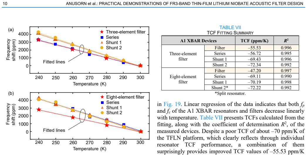
- Temperature or power-induced drifts in resonant frequency might require on-chip trimming circuits that were not tested in the prototypes.
- The same resonators could be combined with thin-film lithium niobate electro-optic modulators on the same substrate to create integrated transmit-receive modules.
Load-bearing premise
Small changes in film thickness and crystal cut direction will produce predictable and repeatable shifts in resonator frequency and coupling strength that match the values needed for the target filter response.
What would settle it
Fabricate resonators with a range of film thicknesses around the design value, measure their actual resonant frequencies, and check whether the observed frequency shifts match the predicted thickness dependence within the tolerance required for the stated 8.58 percent bandwidth.
Figures

read the original abstract
This article presents an approach to control the operating frequency and fractional bandwidth (FBW) of miniature acoustic filters in thin-film lithium niobate (TFLN). More specifically, we used first-order antisymmetric (A1) mode lateral-field-excited bulk acoustic wave resonators (XBARs) to achieve efficient operation at 20.5 GHz. Our technique leverages the thickness-dependent resonant frequency of A1 XBARs, combined with the in-plane anisotropic properties of 128$^\circ$ Y-cut TFLN, to customize filter characteristics. The implemented three-element ladder filter prototype achieves an insertion loss (IL) of only 1.79 dB and a controlled 3-dB FBW of 8.58% at 20.5 GHz, with an out-of-band (OoB) rejection greater than 14.9 dB across the entire FR3 band, while featuring a compact footprint of 0.90 $\times$ 0.74 mm2. Moreover, an eight-element filter prototype shows an IL of 3.80 dB, an FBW of 6.12% at 22.0 GHz, and a high OoB rejection of 22.97 dB, demonstrating the potential for expanding to higher-order filters. As frequency allocation requirements become more stringent in future FR3 bands, our technique showcases promising capability in enabling compact and monolithic filter banks toward next-generation acoustic filters for 6G and beyond.
Editorial analysis
A structured set of objections, weighed in public.
Referee Report
Summary. The manuscript presents an approach to control operating frequency and fractional bandwidth (FBW) of miniature acoustic filters in thin-film lithium niobate (TFLN) for the FR3 band. It uses first-order antisymmetric (A1) mode lateral-field-excited bulk acoustic wave resonators (XBARs) in 128° Y-cut material, exploiting thickness-dependent resonance for frequency setting and in-plane anisotropy for FBW control. Fabricated prototypes are demonstrated: a three-element ladder filter achieves 1.79 dB insertion loss and 8.58% 3-dB FBW at 20.5 GHz with >14.9 dB out-of-band rejection in a 0.90 × 0.74 mm² footprint; an eight-element filter achieves 3.80 dB IL, 6.12% FBW at 22.0 GHz, and 22.97 dB rejection. The work positions these as enabling compact monolithic filter banks for 6G.
Significance. If the reported measured performance holds, the work is significant for providing direct experimental evidence of functional A1 XBAR-based filters at 20–22 GHz with competitive insertion loss, controlled bandwidth, and high out-of-band rejection in compact footprints. The physical fabrication and RF measurement results (rather than purely simulated) strengthen the demonstration of the thickness-and-anisotropy customization technique and its relevance to FR3-band requirements in next-generation wireless systems.
major comments (2)
- [Results section (prototypes)] Results section (prototypes): The headline metrics (IL = 1.79 dB, FBW = 8.58% at 20.5 GHz for the three-element filter; IL = 3.80 dB, FBW = 6.12% at 22.0 GHz for the eight-element filter) are reported as single-point values without error bars, measurement uncertainty, simulation-to-measurement overlay, or statistics across multiple devices. This weakens assessment of whether the thickness-dependent A1 resonance and anisotropy tuning are robust enough to support the claimed customization technique beyond these specific prototypes.
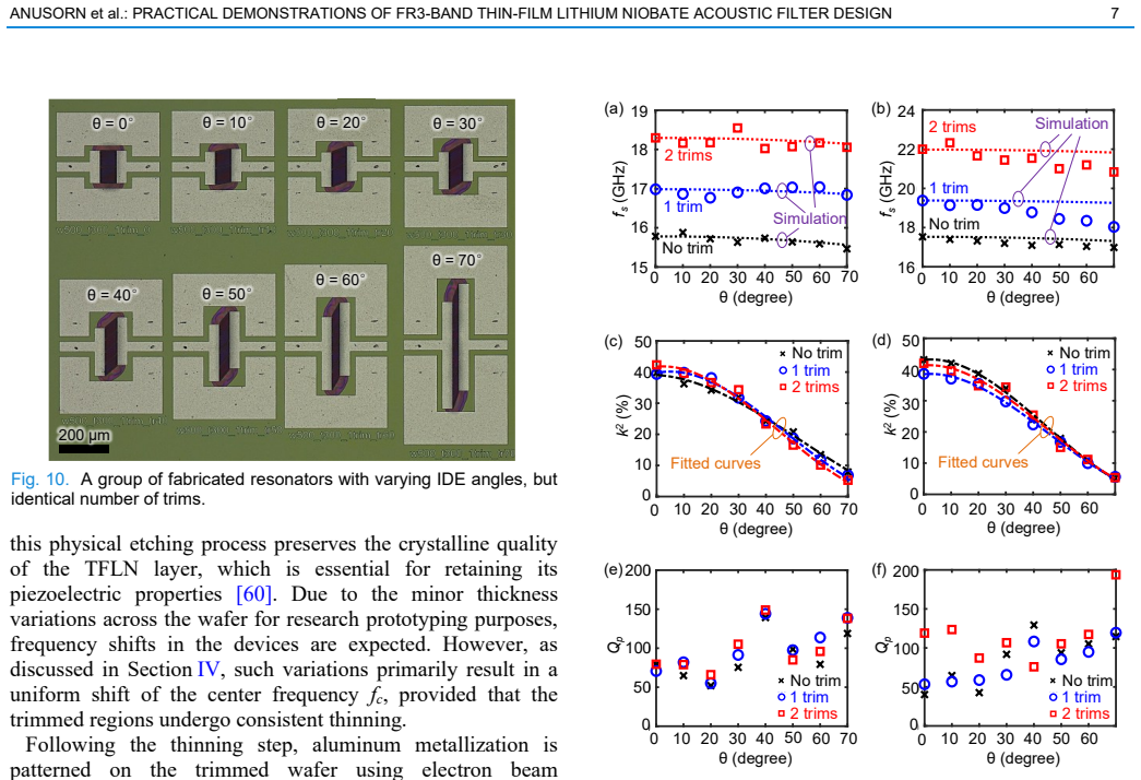
- [Design technique description] Design technique description: No sensitivity analysis, tolerance budget, or discussion of fabrication variations (e.g., film thickness spread of ~5–10 nm or orientation misalignment of 1–2°) is provided, even though the abstract and introduction present thickness dependence and 128° Y-cut anisotropy as the means to reliably customize frequency and FBW. Without such quantification, it remains unclear whether the achieved specs reflect general applicability or required exceptional process control.
minor comments (3)
- [Figures] Figure captions should explicitly state whether traces are measured data, simulated, or both, and include scale bars or annotations for the reported footprints.
- [Results] Consider adding a summary table comparing the two prototypes' key parameters (IL, FBW, rejection, center frequency, size) for clarity.
- [Introduction] Ensure all acronyms (XBAR, FBW, OoB, TFLN) are defined at first use in the main text.
Simulated Author's Rebuttal
We thank the referee for the constructive comments on statistical robustness and fabrication sensitivity. We address each major comment point by point below and indicate the planned revisions.
read point-by-point responses
-
Referee: Results section (prototypes): The headline metrics (IL = 1.79 dB, FBW = 8.58% at 20.5 GHz for the three-element filter; IL = 3.80 dB, FBW = 6.12% at 22.0 GHz for the eight-element filter) are reported as single-point values without error bars, measurement uncertainty, simulation-to-measurement overlay, or statistics across multiple devices. This weakens assessment of whether the thickness-dependent A1 resonance and anisotropy tuning are robust enough to support the claimed customization technique beyond these specific prototypes.
Authors: We agree that the presentation would benefit from additional context on variability. In the revised manuscript we will include simulation-to-measurement overlay plots for both filters and describe the RF measurement setup. We will also report the observed device-to-device variation from the measured samples in the current fabrication run. Comprehensive multi-device statistics were not collected in this proof-of-concept effort; this limitation will be stated explicitly. revision: partial
-
Referee: Design technique description: No sensitivity analysis, tolerance budget, or discussion of fabrication variations (e.g., film thickness spread of ~5–10 nm or orientation misalignment of 1–2°) is provided, even though the abstract and introduction present thickness dependence and 128° Y-cut anisotropy as the means to reliably customize frequency and FBW. Without such quantification, it remains unclear whether the achieved specs reflect general applicability or required exceptional process control.
Authors: We will add a dedicated paragraph in the design section that quantifies the effect of typical fabrication variations. Using wafer-level thickness uniformity data from our process (standard deviation ~5 nm), we will present simulated frequency and FBW shifts and show that the anisotropy-based bandwidth control remains effective within 1–2° orientation misalignment. This will demonstrate that the reported performance is achievable under standard process control. revision: yes
Circularity Check
No circularity: results are experimental measurements from fabricated devices
full rationale
The paper reports measured insertion loss, FBW, and rejection from physical three-element and eight-element ladder filter prototypes fabricated in 128° Y-cut TFLN using A1 XBARs. Performance numbers (1.79 dB IL at 20.5 GHz, 8.58% FBW, etc.) are direct RF measurement outcomes, not outputs of any derivation, equation, or model that reduces to its own inputs by construction. No self-definitional steps, fitted parameters renamed as predictions, or load-bearing self-citations appear in the provided text; the technique description relies on material properties and fabrication rather than circular logic.
Axiom & Free-Parameter Ledger
free parameters (1)
- Piezoelectric film thickness
axioms (2)
- domain assumption A1-mode lateral-field-excited XBARs exhibit resonant frequency that depends on piezoelectric film thickness.
- domain assumption 128° Y-cut TFLN possesses usable in-plane anisotropy that can be leveraged for filter response shaping.
Reference graph
Works this paper leans on
-
[1]
Frequency and bandwidth design toward millimeter - wave thin -film lithium niobate acoustic filters,
O. Barrera et al., “Frequency and bandwidth design toward millimeter - wave thin -film lithium niobate acoustic filters,” IEEE Microw. Wirel. Tech. Lett., doi: 10.1109/LMWT.2025.3559400. TABLE IX ADVANCED FILTER TECHNOLOGY COMPARISONS Ref. Technology fc (GHz) Area (λ02) Height (mm) IL (dB) Rej. (dB)* FBW (%) Shape factor$
-
[2]
GaAs-IPD 28 0.003† N/A 0.76 18.6 22 2.25
-
[3]
DSG-PCB 4.94 0.12 0.5 1.8 25.8 64 1.78
-
[4]
SIW-PCB 10.05 0.24 0.5 0.82 45 12.2 1.43
-
[5]
SIW-TSV 17.96 0.03 0.2 0.85 N/A 89.2 1.52
-
[6]
SIW-TGV 32 0.18 0.4 0.96 N/A 13.1 2.15
-
[7]
TABLE VIII REPORTED FR3 ACOUSTIC FILTERS BEYOND 10 GHZ Ref
SIW-LTCC 27 0.001† 2.8†† 1.36 22.0 18.2 3.38 This work TFLN XBAR (MEMS) 20.5 0.003 0.5 1.79 14.92 8.58# 1.92 22.0 0.007 0.5 3.80 22.97 6.12# 2.37 * OoB rejection is defined as the minimum IL within the frequency range fc ± 10BW from the passband and is extracted from the plot in the reference to maintain consistent comparisons; † excluded GSG probes; †† e...
-
[8]
TFLN XBAR 23.5 2.3 13.6 18.2 No
-
[9]
TFLN XBAR 22.1 1.6 11.9 19.8 No
-
[10]
TFLN XBAR with inductors 19.0 8.0 13.0 2.4 No
-
[11]
Bi-layer P3F AlScN FBAR 10.7 0.7 N/A 5.3 No
-
[12]
Bi-layer P3F TFLN XBAR 23.8 1.5 9.5 19.4 No
-
[13]
4-layer P3F AlScN FBAR 17.4 1.86 5.1 3.9 No 17.4 3.25 12.8 3.4 No This work TFLN XBAR 20.5 1.79 14.92 8.58 Yes 22.0 3.80 22.97 6.12 Yes *OoB rejection is defined as the minimum IL within the frequency range fc ± 10BW from the passband and is extracted from the plot in the reference to maintain consistent comparisons; N/A: insufficient data. 12 ANUSORN et ...
-
[14]
On the road to 6G: Visions, requirements, key technologies, and testbeds,
C.-X. Wang et al. , “On the road to 6G: Visions, requirements, key technologies, and testbeds,” IEEE Commun. Surv. Tutor. , vol. 25, no. 2, pp. 905–974, 2023, doi: 10.1109/COMST.2023.3249835
-
[15]
J. G. Andrews, T. E. Humphreys, and T. Ji, “6G takes shape,” IEEE BITS, vol. 4, no. 1, pp. 2-24, March 2024, doi: 10.1109/MBITS.2024.3504521
-
[16]
H. Miao et al., “Sub-6 GHz to mmWave for 5G -Advanced and beyond: Channel measurements, characteristics and impact on system performance,” IEEE IEEE J. Sel. Areas Commun. , vol. 41, no. 6, pp. 1945-1960, June 2023, doi: 10.1109/JSAC.2023.3274175
-
[17]
Cellular wireless networks in the upper mid-band,
S. Kang et al., “Cellular wireless networks in the upper mid-band,” IEEE Open J. Commun. Soc. , vol. 5, pp. 2058 -2075, 2024, doi: 10.1109/OJCOMS.2024.3373368
-
[18]
D. Shakya et al., “Comprehensive FR1(C) and FR3 lower and upper mid- band propagation and material penetration loss measurements and channel models in indoor environment for 5G and 6G,” IEEE Open J. Commun. Soc. , vol vol. 5, pp. 5192 -5218, 2024, doi: 10.1109/OJCOMS.2024.3431686
-
[19]
Davidson, National Spectrum Strategy Implementation Plan, Washington, DC, USA, Mar
A. Davidson, National Spectrum Strategy Implementation Plan, Washington, DC, USA, Mar. 2024
work page 2024
-
[20]
G. Shen, Z. He, W. Feng, B. Wen, Q. Xue, and W. Che, “Lumped - distributed on-chip resonators with multistubs reused and its application to stopband extended IPD bandpass filters,” IEEE Trans. Microw. Theory Tech., vol. 72, no. 4, pp. 2498 -2507, April 2024, doi: 10.1109/TMTT.2023.3316358
-
[21]
D. M. Pozar, Microwave engineering. Hoboken, Nj: Wiley, 2012
work page 2012
-
[22]
Hong, Microstrip filters for RF/microwave applications
J.-S. Hong, Microstrip filters for RF/microwave applications . Hoboken, N.J.: Wiley, 2011
work page 2011
-
[23]
S. Xu, K. Ma, F. Meng, and K. S. Yeo, “Novel defected ground structure and two-side loading scheme for miniaturized dual -band SIW bandpass filter designs,” IEEE Microw. Wirel. Compon. Lett. , vol. 25, no. 4, pp. 217-219, April 2015, doi: 10.1109/LMWC.2015.2400916
-
[24]
W. Yuan, X. Liu, H. Lu, W. Wu and N. Yuan, “Flexible design method for microstrip bandstop, highpass, and bandpass filters using similar defected ground structures,” IEEE Access, vol. 7, pp. 98453-98461, 2019, doi: 10.1109/ACCESS.2019.2928816
-
[25]
A compact, hybrid SIW filter with controllable transmission zeros and high selectivity,
G. Lin and Y. Dong, “A compact, hybrid SIW filter with controllable transmission zeros and high selectivity,” IEEE Trans. Circuits Syst. II: Express Br. , vol. 69, no. 4, pp. 2051 -2055, April 2022, doi: 10.1109/TCSII.2022.3144268
-
[26]
Y. Zhu, Y. Dong, J. Bornemann, L. Gu, and D. F. Mamedes, “SIW triplets including meander -line and CRLH resonators and their applications to quasi-elliptic filters,” IEEE Trans. Microw. Theory Tech. , vol. 71, no. 5, pp. 2193-2206, May 2023, doi: 10.1109/TMTT.2022.3225447
-
[27]
C. Fan, X. Liu, N. Liu, and Z. Zhu, “Compact bandpass filters with low loss and TZs based on 1/n mode circle -SIW in through silicon vias (TSVs) technology,” IEEE Trans. Microw. Theory Tech. , vol. 72, no. 9, pp. 5095-5105, Sept. 2024, doi: 10.1109/TMTT.2024.3370823
-
[28]
A low -loss slow wave SIW bandpass filter with blind via-holes using TGV technology,
L. Wang et al., “A low -loss slow wave SIW bandpass filter with blind via-holes using TGV technology,” IEEE Microw. Wirel. Tech. Lett., vol. 34, no. 3, pp. 271-274, March 2024, doi: 10.1109/LMWT.2024.3350110
-
[29]
W. Li et al ., “Glass -based single -layer slow wave SIW filter with embedded composite right -/ left -handed resonator,” IEEE Trans. Microw. Theory Tech. , vol. 73, no. 2, pp. 1105 -1116, Feb. 2025, doi: 10.1109/TMTT.2024.3440250
-
[30]
Low-loss self- packaged Ka -Band LTCC filter using artificial multimode SIW resonator,
X. Huang, X. Zhang, L. Zhou, J. -X. Xu, and J. -F. Mao, “Low-loss self- packaged Ka -Band LTCC filter using artificial multimode SIW resonator,” IEEE Trans. Circuits Syst. II: Express Br. , vol. 70, no. 2, pp. 451-455, Feb. 2023, doi: 10.1109/TCSII.2022.3173712
-
[31]
G. Shen, W. Yang, W. Feng, Q. Xue, and W. Che, “Vertically stacked millimeter-wave LTCC filters with cavity-mode suppression for system- in-package application,” IEEE Trans. Microw. Theory Tech., vol. 71, no. 6, pp. 2532-2544, June 2023, doi: 10.1109/TMTT.2022.3230722
- [32]
-
[33]
Microwave acoustic devices: Recent advances and outlook,
S. Gong, R. Lu, Y. Yang, L. Gao, and A. E. Hassanien, “Microwave acoustic devices: Recent advances and outlook,” IEEE J. Microwaves , vol. 1, no. 2, pp. 601-609, April 2021, doi: 10.1109/JMW.2021.3064825
-
[34]
From microwave acoustic filters to millimeter-wave operation and new applications,
A. Hagelauer et al., “From microwave acoustic filters to millimeter-wave operation and new applications,” IEEE J. Microwaves, vol. 3, no. 1, pp. 484-508, Jan. 2023, doi: 10.1109/JMW.2022.3226415
-
[35]
P. Warder and A. Link, “Golden age for filter design: Innovative and proven approaches for acoustic filter, duplexer, and multiplexer design,” IEEE Microw. Mag. , vol. 16, no. 7, pp. 60 -72, Aug. 2015, doi: 10.1109/MMM.2015.2431236
-
[36]
Hashimoto, Surface acoustic wave devices in telecommunications: Modelling and simulation
K. Hashimoto, Surface acoustic wave devices in telecommunications: Modelling and simulation. Berlin; New York: Springer, 2000
work page 2000
-
[37]
High power, wideband single crystal XBAW technology for sub -6 GHz micro RF filter applications,
R. Vetury, M. D. Hodge, and J. B. Shealy, “High power, wideband single crystal XBAW technology for sub -6 GHz micro RF filter applications,” in Proc. IUS , Kobe, Japan, 2018, pp. 206 –212, doi: 10.1109/ULTSYM.2018.8580045
-
[38]
Hashimoto, RF Bulk acoustic wave filters for communications
K. Hashimoto, RF Bulk acoustic wave filters for communications . Norwood, Mass.: Artech House, 2009
work page 2009
-
[39]
33 GHz overmoded bulk acoustic resonator,
Z. Schaffer, P. Simeoni and G. Piazza, “33 GHz overmoded bulk acoustic resonator,” IEEE Microw. Wirel. Compon. Lett. , vol. 32, no. 6, pp. 656 - 659, June 2022, doi: 10.1109/LMWC.2022.3166682
-
[40]
15-GHz epitaxial AlN FBARs on SiC substrates,
W. Zhao et al., “15-GHz epitaxial AlN FBARs on SiC substrates,” IEEE Electron Device Lett. , vol. 44, no. 6, pp. 903 -906, June 2023, doi: 10.1109/LED.2023.3268863
-
[41]
Millimeter wave thin -film bulk acoustic resonator in sputtered scandium aluminum nitride,
S. Cho et al ., “Millimeter wave thin -film bulk acoustic resonator in sputtered scandium aluminum nitride,” J. Microelectromechanical Syst., vol. 32, no. 6, pp. 529 -532, Dec. 2023, doi: 10.1109/JMEMS.2023.3321284
-
[42]
A 19 GHz all -epitaxial Al₀.₈Sc₀.₂N cascaded FBAR for RF filtering applications,
M. Park et al., “A 19 GHz all -epitaxial Al₀.₈Sc₀.₂N cascaded FBAR for RF filtering applications,” IEEE Electron Device Lett., vol. 45, no. 7, pp. 1341-1344, July 2024, doi: 10.1109/LED.2024.3404477
-
[43]
5 GHz lithium niobate MEMS resonators with high FoM of 153,
Y. Yang, A. Gao, R. Lu, and S. Gong, “5 GHz lithium niobate MEMS resonators with high FoM of 153,” in Proc. MEMS, Las Vegas, NV, USA, 2017, pp. 942-945, doi: 10.1109/MEMSYS.2017.7863565
-
[44]
5 GHz laterally -excited bulk -wave resonators (XBARs) based on thin platelets of lithium niobate,
V. Plessky, et al. , “5 GHz laterally -excited bulk -wave resonators (XBARs) based on thin platelets of lithium niobate,” Electronics Letters, vol. 55, no. 2, pp. 98-100, Jan. 2019, doi: 10.1049/el.2018.7297
-
[45]
Multimeter-wave acoustic resonators,
R. Lu, et al., “Multimeter-wave acoustic resonators,” U.S. Patent 0 062 738, Feb. 10, 2025
work page 2025
-
[46]
R. Lu, “Recent advances in high -performance millimeter-Wave acoustic resonators and filters using thin -film lithium niobate,” Prog. Quantum Electron., vol. 100 –101, p. 100565, May 2025, doi: 10.1016/j.pquantelec.2025.100565
-
[47]
A1 resonators in 128° Y -cut lithium niobate with electromechanical coupling of 46.4%,
R. Lu, Y. Yang, S. Link, and S. Gong, “A1 resonators in 128° Y -cut lithium niobate with electromechanical coupling of 46.4%,” J. Microelectromechanical Syst., vol. 29, no. 3, pp. 313-319, June 2020, doi: 10.1109/JMEMS.2020.2982775
-
[48]
38.7 GHz thin film lithium niobate acoustic filter,
O. Barrera, S. Cho, J. Kramer, V. Chulukhadze, J. Campbell, and R. Lu, “38.7 GHz thin film lithium niobate acoustic filter,” in Proc. IMFW , Cocoa Beach, FL, USA, 2024, pp. 87 -90, doi: 10.1109/IMFW59690.2024.10477121
-
[49]
Thin-film lithium niobate acoustic filter at 23.5 GHz with 2.38 dB IL and 18.2% FBW,
O. Barrera et al., “Thin-film lithium niobate acoustic filter at 23.5 GHz with 2.38 dB IL and 18.2% FBW,” J. Microelectromechanical Syst., vol. 32, no. 6, pp. 622-625, Dec. 2023, doi: 10.1109/JMEMS.2023.3314666
-
[50]
Transferred thin film lithium niobate as millimeter wave acoustic filter platforms,
O. Barrera et al., “Transferred thin film lithium niobate as millimeter wave acoustic filter platforms,” in Proc. MEMS, Austin, TX, USA, 2024, pp. 23-26, doi: 10.1109/MEMS58180.2024.10439593
-
[51]
Y. Xie et al. , “Tunable electromechanical coupling coefficient of a laterally excited bulk wave resonator with composite piezoelectric film,” Micromachines, vol. 13, no. 4, p. 641, Apr. 2022, doi: 10.3390/mi13040641
-
[52]
X. Fang et al., “High-steepness and low-loss SAW filters with fractional bandwidth from 3.7% to 12.4% on a monolithic X-cut LiNbO3/SiO2/SiC substrate,” IEEE Trans. Microw. Theory Tech., vol. 72, no. 11, pp. 6314- 6323, Nov. 2024, doi: 10.1109/TMTT.2024.3403916
-
[53]
Wideband hybrid monolithic lithium niobate acoustic filter in the K -Band,
L. Gao, Y. Yang, and S. Gong, “Wideband hybrid monolithic lithium niobate acoustic filter in the K -Band,” IEEE Trans. Ultrason. Ferroelectr. Freq. Control. , vol. 68, no. 4, pp. 1408 -1417, April 2021, doi: 10.1109/TUFFC.2020.3035123
-
[54]
A. Kochhar et al., “X-band bulk acoustic wave resonator (XBAW) using periodically polarized piezoelectric films (P3F),” in Proc. IUS, Montreal, QC, Canada, 2023, pp. 1-4, doi: 10.1109/IUS51837.2023.10306825
-
[55]
S. Cho et al., “23.8-GHz acoustic filter in periodically poled piezoelectric film lithium niobate with 1.52 -dB IL and 19.4% FBW,” IEEE Microw. Wirel. Technol. Lett. , vol. 34, no. 4, pp. 391 -394, April 2024, doi: 10.1109/LMWT.2024.3368354
-
[56]
Izhar et al., “Periodically poled aluminum scandium nitride bulk acoustic wave resonators and filters for communications in the 6G era,” Microsyst. Nanoeng., vol. 11, no. 1, Jan. 2025, doi: 10.1038/s41378-024-00857-4
-
[57]
SAW filters on LiNbO3/SiC heterostructure for 5G n77 and n78 band applications,
H. Xu et al., “SAW filters on LiNbO3/SiC heterostructure for 5G n77 and n78 band applications,” IEEE Trans. Ultrason. Ferroelectr. Freq. Control., vol. 70, no. 9, pp. 1157 -1169, Sept. 2023, doi: 10.1109/TUFFC.2023.3299635. ANUSORN et al.: PRACTICAL DEMONSTRATIONS OF FR3-BAND THIN-FILM LITHIUM NIOBATE ACOUSTIC FILTER DESIGN 13
-
[58]
Modified Butterworth-Van Dyke circuit for FBAR resonators and automated measurement system,
J. D. Larson, P. D. Bradley, S. Wartenberg, and R. C. Ruby, “Modified Butterworth-Van Dyke circuit for FBAR resonators and automated measurement system,” in Proc. IUS, San Juan, PR, USA, 2000, pp. 863 - 868 vol.1, doi: 10.1109/ULTSYM.2000.922679
-
[59]
General synthesis methodology for the design of acoustic wave ladder filters and duplexers,
A. Giménez, J. Verdú and P. De Paco Sánchez, “General synthesis methodology for the design of acoustic wave ladder filters and duplexers,” IEEE Access , vol. 6, pp. 47969 -47979, 2018, doi: 10.1109/ACCESS.2018.2865808
-
[60]
A synthesis approach to acoustic wave ladder filters and duplexers starting with shunt resonator,
E. Guerrero, P. Silveira, J. Verdú, Y. Yang, S. Gong and P. de Paco, “A synthesis approach to acoustic wave ladder filters and duplexers starting with shunt resonator,” IEEE Trans. Microw. Theory Tech., vol. 69, no. 1, pp. 629-638, Jan. 2021, doi: 10.1109/TMTT.2020.3033554
-
[61]
Synthesis of Chebyshev/elliptic filters using minimum acoustic wave resonators,
S. -Y. Tseng and R. -B. Wu, “Synthesis of Chebyshev/elliptic filters using minimum acoustic wave resonators,” IEEE Access, vol. 7, pp. 103456 - 103462, 2019, doi: 10.1109/ACCESS.2019.2930904
-
[62]
Bandpass phase correction methodology for ladder-type acoustic filters,
I. Evdokimova, J. Verdú and P. de Paco, “Bandpass phase correction methodology for ladder-type acoustic filters,” in Proc. 48th Eur. Microw. Conf. (EuMC) , Madrid, Spain, Sep. 2018, pp. 683 –686, doi: 10.23919/EuMC.2018.8541557
-
[63]
General synthesis methodology for acoustic wave ladder filters in the bandpass domain,
S. Cano, C. Caballero, O. Barrera, R. Lu, J. Verdú and P. de Paco, “General synthesis methodology for acoustic wave ladder filters in the bandpass domain,” IEEE Trans. Microw. Theory Tech. , doi: 10.1109/TMTT.2025.3565809
-
[64]
Exact synthesis of hybrid acoustic –electromagnetic filters with wideband Chebyshev responses,
G. Ariturk, N. R. Almuqati, Y. Yu, E. T. -T. Yen, A. Fruehling and H. H. Sigmarsson, “Exact synthesis of hybrid acoustic –electromagnetic filters with wideband Chebyshev responses,” IEEE Trans. Microw. Theory Tech., vol. 72, no. 5, pp. 3185 -3199, May 2024, doi: 10.1109/TMTT.2023.3319987
-
[65]
R. Lu and S. Gong, “RF acoustic microsystems based on suspended lithium niobate thin films: advances and outlook,” J. Micromech. Microeng., vol. 31, no. 11, p. 114001, Sep. 2021, doi: 10.1088/1361- 6439/ac288f
-
[66]
K. Shibayama, K. Yamanouchi, H. Sato, and T. Meguro, “Optimum cut for rotated Y-cut LiNbO3 crystal used as the substrate of acoustic- surface-wave filters,” Proc. IEEE, vol. 64, no. 5, pp. 595-597, May 1976, doi: 10.1109/PROC.1976.10181
-
[67]
IEEE Standard on Piezoelectricity, ANSI/IEEE, 176-1987 , 1988
work page 1987
-
[68]
Lithium niobate: Summary of physical properties and crystal structure,
R. S. Weis and T. K. Gaylord, “Lithium niobate: Summary of physical properties and crystal structure,” Appl. Phys. A, Solids Surf., vol. 37, no. 4, pp. 191–203, Aug. 1985, doi: 10.1007/BF00614817
-
[69]
Morgan, Surface Acoustic Wave Filters
D. Morgan, Surface Acoustic Wave Filters. Amsterdam, The Netherlands: Elsevier, 2007
work page 2007
-
[70]
Low-Loss 5-GHz First-Order Antisymmetric Mode Acoustic Delay Lines in Thin-Film Lithium Niobate,
R. Lu, Y. Yang, S. Link and S. Gong, “Low -loss 5 -GHz first -order antisymmetric mode acoustic delay lines in thin -film lithium niobate,” IEEE Trans. Microw. Theory Tech., vol. 69, no. 1, pp. 541-550, Jan. 2021, doi: 10.1109/TMTT.2020.3022942
-
[71]
A generalized acoustic framework for multilayer piezoelectric platforms ,
J. Kramer and R. Lu, “A generalized acoustic framework for multilayer piezoelectric platforms ,” IEEE Trans. Ultrason. Ferroelectr. Freq. Control., vol. 72, no. 9, pp. 1302 -1311, Sept. 2025, doi: 10.1109/TUFFC.2025.3595433
-
[72]
Analysis of 5−10 GHz Higher-Order Lamb Acoustic Waves in Thin-Film Scandium Aluminum Nitride,
V. Chulukhadze et al ., “Frequency scaling millimeter wave acoustic resonators using ion beam trimmed lithium niobate,” in Proc. EFTF/IFCS, Toyama, Japan, 2023, pp. 1 -4, doi: 10.1109/EFTF/IFCS57587.2023.10272038
-
[73]
Accurate extraction of large electromechanical coupling in piezoelectric MEMS resonators,
R. Lu, M. -H. Li, Y. Yang, T. Manzaneque and S. Gong, “Accurate extraction of large electromechanical coupling in piezoelectric MEMS resonators,” J. Microelectromechanical Syst., vol. 28, no. 2, pp. 209-218, April 2019, doi: 10.1109/JMEMS.2019.2892708
-
[74]
Acoustic and electromagnetic co -modeling of piezoelectric devices at millimeter wave,
T. Zhang, Y. -W. Chang, O. Barrera, N. Ahmed, J. Kramer, and R. Lu, “Acoustic and electromagnetic co -modeling of piezoelectric devices at millimeter wave,” J. Microelectromechanical Syst. , vol. 33, no. 5, pp. 640-645, Oct. 2024, doi: 10.1109/JMEMS.2024.3431576
-
[75]
Z. -Q. Lee, J. Raj, K. Sandeep Sharma, G. Pillai and M. -H. Li, “Cryogenic characterization of low -loss thin -film lithium niobate on sapphire shear horizontal surface acoustic wave devices,” IEEE Trans. Ultrason. Ferroelectr. Freq. Control., vol. 72, no. 1, pp. 55-63, Jan. 2025, doi: 10.1109/TUFFC.2024.3504285
-
[76]
J. Kramer et al., “Trilayer periodically poled piezoelectric film lithium niobate resonator,” in Proc. IUS, Montreal, QC, Canada, 2023, pp. 1 -4, doi: 10.1109/IUS51837.2023.10306831
-
[77]
O. Barrera et al., “Fundamental antisymmetric mode acoustic resonator in periodically poled piezoelectric film lithium niobate,” in Proc. IUS , Montreal, QC, Canada, 2023, pp. 1 -4, doi: 10.1109/IUS51837.2023.10307135
-
[78]
Piezoelectric microacoustic metamaterial filters,
O. Kaya, X. Zhao and C. Cassella, “Piezoelectric microacoustic metamaterial filters,” IEEE Trans. Ultrason. Ferroelectr. Freq. Control., vol. 71, no. 9, pp. 1063 -1073, Sept. 2024, doi: 10.1109/TUFFC.2024.3432849
-
[79]
Switchable SAW resonators and ladder filters composed of interdigitated combs,
R. Alcorta Galván et al., “Switchable SAW resonators and ladder filters composed of interdigitated combs,” IEEE Trans. Ultrason. Ferroelectr. Freq. Control. , vol. 71, no. 10, pp. 1302 -1313, Oct. 2024, doi: 10.1109/TUFFC.2024.3441531
discussion (0)
Sign in with ORCID, Apple, or X to comment. Anyone can read and Pith papers without signing in.