REVIEW 4 major objections 6 minor 3 references
Transformer IMU Calibrator: Dynamic On-body IMU Calibration for Inertial Motion Capture
T0 review · 4 major / 6 minor · reviewed 2026-08-07 · deepseek-v4-flash
Pith's one-line read This paper claims that the two error sources that corrupt body-worn inertial sensors — coordinate drift and wearing offset — can be estimated continuously from a short window of IMU readings, replacing the one-time static calibration and…
desk verdict A genuine new idea with solid in-distribution validation, but the headline claim overreaches beyond the training envelope. read the letter →
The pith
A machine-rendered reading of the paper's core claim, the machinery that carries it, and where it could break.
The reading
What carries the argument
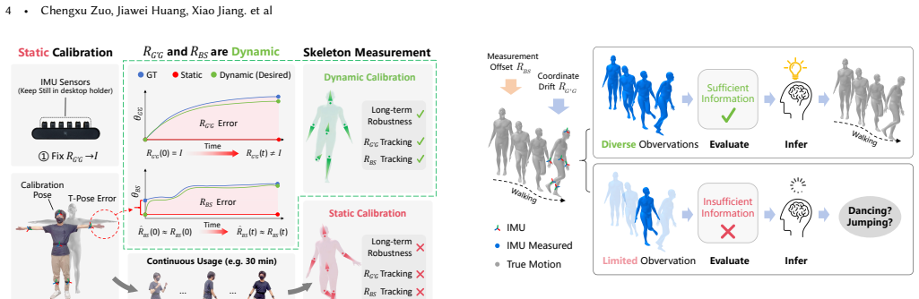
The two calibration matrices are $R_{G'G}$, the coordinate drift rotating the global frame due to magnetic interference and gyro integration error, and $R_{BS}$, the sensor-to-bone measurement offset from imperfect wearing. The argument runs through Eq. (1), which writes the raw IMU reading as $R_{\mathrm{IMU}}(t)=R_{G'G}(t)\,R_{GB}(t)\,R_{BS}(t)$, and through two relaxed assumptions: the Short-term Static Assumption (the matrices barely change inside a window) and the Short-term Diversity Assumption (the IMU orientations in the window are not all the same). These shrink the solution space enough that a Transformer encoder with two pooling-mapping heads — the TIC network — can regress the matrices from $n$ frames of orientation and acceleration. The acceleration input is what lets the network tell the two matrices apart, because acceleration depends on $R_{G'G}$ but not on $R_{BS}$. A trigger based on rotation diversity discretizes Euler angles into a $24 \times 12 \times 24$ grid and only applies the network's output when enough grid cells have been visited.
What would settle it
Take the six-sensor setup and deliberately induce a step change in calibration parameters — for example, re-seat the forearm sensor mid-session or pass a strong magnet near the hip — then check whether TIC's estimated $R_{G'G}$ follows the jump or lags until the next diverse window; a test where the true drift steps by more than the simulated ±60 degrees of yaw and the calibrated pose error spikes would show the short-term static assumption does not hold.
Extended reading notes
Core claim
The central claim is that the two unknown error matrices — the coordinate drift $R_{G'G}(t)$ and the measurement offset $R_{BS}(t)$ — can be recovered in real time from a short window of raw IMU readings, even though the measurement equation $R_{\mathrm{IMU}}(t)=R_{G'G}(t)\,R_{GB}(t)\,R_{BS}(t)$ is underdetermined. The paper shows this becomes solvable once two relaxed assumptions replace the usual long-term static assumption: the matrices change negligibly inside a short window, and the window's IMU orientations are diverse. A Transformer network (TIC) trained on synthetic paired data learns the mapping from $n$ frames of orientation and acceleration to the two matrices, and a rotation-diversity trigger decides when the mapping's output is reliable enough to apply. On a one-hour real dataset, average orientation measurement error falls from 49.98 degrees with static calibration to 15.20 degrees with TIC, and six existing sparse-IMU pose estimators all improve.
Load-bearing premise
The load-bearing premise is that real drift and offset stay inside the ranges used to synthesize the training data (yaw drift within ±60 degrees for non-root sensors, offsets within ±45 degrees per axis) and change slowly enough inside a short window for the short-term static assumption to hold; if a user's error jumps suddenly or falls outside those ranges, the method has no reliable output.
Editorial extensions
If this is right
- Sparse-IMU capture can start from any pose and self-correct after a short burst of diverse motion, removing the T-pose and heading-reset requirements of static calibration.
- Long sessions stay accurate: without TIC the six tested estimators degrade to angular errors around 30–37 degrees, while with TIC they stay around 15–19 degrees.
- The calibrator is fast enough for continuous background use: rotation-diversity computation takes 2.5 ms and network inference 2 ms, supporting updates every second.
- Imperfect initial calibration poses are absorbed automatically, including forearm offsets averaging about 29–33 degrees in the collected data.
- The same pipeline transfers to consumer-grade IMUs in phones, watches, and earbuds, reducing average orientation measurement error from 23.61 degrees to 18.95 degrees on the IMUPoser dataset.
Reading between the lines
- The authors do not test the failure boundary directly, but the training ranges in Table 8 imply that a user whose drift exceeds the simulated yaw range of ±60 degrees (or offsets beyond ±45 degrees) will receive estimates the model was never trained to produce; a follow-up could map OME as a function of the true drift magnitude to find the practical envelope.
- Because the network outputs incremental updates $\Delta R_{G'G}$ and $\Delta R_{BS}$ rather than absolute matrices, the same calibrator could be stacked after any existing static calibration routine and used to correct only the residual error, not just replace the routine entirely.
- A low-activity user (office work, watching TV) will starve the diversity trigger, so a practical deployment would likely pair this method with a vision- or magnetometer-based fallback during sedentary periods — an extension the paper does not explore.
- The synthetic-to-real recipe suggests a cheap porting path: re-sample the Euler-angle ranges to match a new sensor population (e.g., noisier consumer IMUs or looser attachment) and fine-tune, which could extend the method beyond the six-body configuration tested here.
Editorial analysis
A structured set of objections, weighed in public.
Referee Report
Summary. This paper proposes Transformer IMU Calibrator (TIC), a dynamic calibration method for sparse inertial motion capture. The method replaces the standard assumption that the coordinate drift R_G'G and measurement offset R_BS are constant for an entire session with two weaker assumptions: that these quantities change negligibly within a short time window and that the IMU readings within that window are diverse. A Transformer is trained on synthetic AMASS/DIP data with randomly sampled R_G'G and R_BS to regress residual updates from a 256-frame window of six IMU orientations and accelerations, and a rotation-diversity trigger gates which updates are applied. The authors evaluate on a new one-hour, five-subject dataset with optical ground truth, reporting a reduction in average orientation measurement error from 49.98 degrees to 15.20 degrees, and they show improvements in six downstream sparse-IMU pose estimators, along with ablations and a 10-run reproducibility study.
Significance. If the method generalizes beyond its training envelope, it is a valuable step: it removes the explicit T-pose calibration step, addresses long-term drift, and contributes a public dataset and code. The central result is not simply re-fitting the answer, because the ground-truth R_G'G and R_BS are derived from independently measured optical motion capture (Eq. 7), and the ablation study gives clear evidence that the acceleration auxiliary input matters (Table 4). The 10-run reproducibility study (Appendix J) and evaluation on consumer-grade IMUs (Table 7) and Xsens IMUs (Table 15) are additional strengths. The main weakness is that generalization is currently conditional on the synthetic training distribution and on the validity of Assumption 2, and several claims in the abstract and conclusion are stronger than the evidence supports.
major comments (4)
- [§5.1, Appendix A (Table 8), Appendix C (Table 9)] The synthetic training distribution is effectively tuned to the evaluation distribution. Appendix C states that the observed forearm T-pose errors (32.86 +/- 11.43 degrees) are 'well covered' by the +/-45 degree R_BS range used in Appendix A, so the simulation box is not an independent prior over deployment conditions. The paper provides no out-of-distribution evaluation, e.g., with R_BS beyond +/-45 degrees, with mixed-axis R_G'G drift as seen for IMU 2 in Fig. 13, or with residual deltas outside the prescribed ranges. Because the headline claim is implicit calibration for arbitrary use, the behavior outside this box is load-bearing. Please add synthetic out-of-distribution tests or otherwise quantify the coverage of realistic deployment conditions.
- [§4.3 (Algorithm 2), §5.1, Fig. 13] Assumption 2 is never directly tested. Training draws one constant R_G'G and R_BS per 256-frame sequence (Section 5.1), while deployment estimates residual deltas on windows in which the underlying R_G'G is drifting. At the observed drift rate of about 0.309 degrees/s (Fig. 13), R_G'G changes by roughly 2.6 degrees within one 8.53-s window, which is not negligible relative to the 9.18-degree mean R_G'G error reported in Table 4. The paper should include a controlled synthetic experiment with within-window parameter drift, or show that the residual process seen in deployment lies within the constant-per-window training distribution.
- [§5.7, Table 6] The claim that dynamic calibration significantly enhances translation estimation is supported only in the ego-yaw frame. In the SMPL (fixed global) frame, TIC increases translation error at every reported window (1s: 18.03 vs 14.09 cm; 10s: 49.50 vs 41.69 cm). Since the abstract and conclusion promise 'long-term and accurate motion capture using sparse IMUs,' the paper should either restrict the claim to body-relative pose or explain why the degradation in the fixed global frame is acceptable for the target application. This caveat should appear in the abstract and conclusion, not only in a sentence inside Section 5.7.
- [§5.4, Table 2; §6] The headline OME/AME improvement is demonstrated on a single one-hour dataset whose measured parameters fall inside the synthetic box, while Section 6 concedes failure under large sudden changes, low-activity windows, and irregular motions. The paper should provide a per-subject, per-activity, or per-window breakdown of the errors so that readers can assess how often the method operates in regimes where it is expected to help. Without such a breakdown, the average 49.98-to-15.20 reduction may mask substantial portions of time where TIC is not triggered or is less accurate.
minor comments (6)
- [§2.1] There are typographical errors in the related-work section: 'arbirtary' should be 'arbitrary' and 'hight efficiency' should be 'high efficiency.'
- [Table 1 and §5.4] The dataset naming is inconsistent: Table 1 uses 'DS AMS,' 'DS DIP,' and 'DS TIC,' while the text uses 'DSTIC' and 'DS DIP.' Please standardize the names.
- [§4.3, Algorithm 2] The buffer semantics of Algorithm 2 are ambiguous. If B_n is a fixed-length queue, the condition |B_n|==n and the clear operation are at odds; if B_n is a growing list capped at n, the condition may never be met because the 1-s timing signal does not align with the 256-frame fill time. Please clarify whether the buffer is a sliding window and how the timing signal interacts with it.
- [Appendix G] There is a typo in the training details: 'The a_IMU were divide by 30' should read 'The a_IMU were divided by 30,' and there is a stray comma after the citation '[Zhou et al. 2019].'
- [Fig. 13 and Table 2] The text refers to 'the IMU on the right hand (IMU 2),' while Table 2 and the data-collection description consistently call this location the right forearm. Please use consistent body-location naming.
- [§5.8, Table 7] Table 7 shows that for the right front pocket sensor, OME with TIC (10.64 degrees) is worse than without TIC (9.18 degrees). The claim that TIC 'significantly reduced OME in the IMUPoser dataset' should be accompanied by a per-sensor caveat.
Circularity Check
No significant circularity: the TIC mapping is trained on synthetic paired data and tested against independent optical ground truth; the test-set-tuned synthetic envelope and hyperparameters are generalization risks, not circular reductions.
full rationale
The claimed derivation chain is not circular. The network is trained with Eq. 6 to regress R_G'G(n) and R_BS(n) from synthetic IMU sequences generated by applying random Euler-angle rotations to AMASS/DIP data (Sec. 5.1, Appendix A, Table 8), and it is evaluated on DS_TIC, whose ground-truth drift and offset are computed independently from optical markers via Eq. 7 (Sec. 5.2). The test labels therefore do not enter the training objective, and the w-TIC vs w/o-TIC comparisons (Tables 2 and 3) are externally grounded improvements, not constructions equivalent to the inputs. The main caveats are three test-set-informed design choices: Appendix C states that the observed T-pose errors are 'well covered' by the R_BS sampling range, meaning the simulator's envelope (Table 8) is deliberately matched to the evaluation distribution; Table 11's update interval t=1s is chosen from errors measured on DS_TIC; and Table 16's delta-parameterization is chosen on the same set. These choices weaken generalization claims and make the evaluation partly in-distribution, but they do not make the predicted OME/AME values equal to fitted parameters by construction; the network still must learn a nontrivial mapping and fails on out-of-envelope conditions, as the Limitations section (Sec. 6) concedes for sudden changes, low activity, and irregular motions. No load-bearing self-citation or imported uniqueness theorem is used. Overall, this is a correct non-circular finding with minor generalization-risk caveats, hence score 1.
Assumptions & free parameters
free parameters (6)
- R_BS synthetic sampling range =
U(-45,45) degrees on x, y, z axes (Table 8)
- R_GG' synthetic sampling ranges =
root: U(-20,20), 0, U(-20,20); non-root: U(-20,20), U(-60,60), U(-20,20) (Table 8)
- Per-joint rotation diversity threshold T_R =
15 (hip), 25 (head), 30 (left/right lower leg and left forearm), 50 (right forearm) (Table 10)
- Update interval t =
1 s (Table 11)
- Window length n =
256 frames (8.53 s at 30 Hz)
- Euler angle discretization step =
15 degrees (24x12x24 grid)
assumptions (6)
- domain assumption Assumption 2: R_GG' and R_BS change negligibly within a short time window.
- domain assumption Assumption 3: IMU readings within the window are diverse.
- domain assumption The world drift R_W'G decomposes into a non-solvable yaw component R_W'G' and a solvable component R_GG', defining the ego-yaw frame.
- domain assumption Uniform random Euler-angle sampling of R_GG' and R_BS over the ranges in Table 8 covers real-world drift and offset distributions.
- domain assumption The hardware-level GA removal model with g_bias fixed to the true gravity vector (Eq. 10).
- domain assumption The human motion prior in AMASS and DIP is representative of real user motion.
invented entities (1)
-
ego-yaw coordinate system
Cite this review
Pith. "Pith review of Transformer IMU Calibrator: Dynamic On-body IMU Calibration for Inertial Motion Capture." pith.science (2026). https://pith.science/paper/EUR3P2E5
@misc{pith2026250610580,
  author       = {Pith},
  title        = {Pith review of: Transformer IMU Calibrator: Dynamic On-body IMU Calibration for Inertial Motion Capture},
  year         = {2026},
  howpublished = {\url{https://pith.science/paper/EUR3P2E5}},
  note         = {Machine review of arXiv:2506.10580}
}
read the original abstract
In this paper, we propose a novel dynamic calibration method for sparse inertial motion capture systems, which is the first to break the restrictive absolute static assumption in IMU calibration, i.e., the coordinate drift RG'G and measurement offset RBS remain constant during the entire motion, thereby significantly expanding their application scenarios. Specifically, we achieve real-time estimation of RG'G and RBS under two relaxed assumptions: i) the matrices change negligibly in a short time window; ii) the human movements/IMU readings are diverse in such a time window. Intuitively, the first assumption reduces the number of candidate matrices, and the second assumption provides diverse constraints, which greatly reduces the solution space and allows for accurate estimation of RG'G and RBS from a short history of IMU readings in real time. To achieve this, we created synthetic datasets of paired RG'G, RBS matrices and IMU readings, and learned their mappings using a Transformer-based model. We also designed a calibration trigger based on the diversity of IMU readings to ensure that assumption ii) is met before applying our method. To our knowledge, we are the first to achieve implicit IMU calibration (i.e., seamlessly putting IMUs into use without the need for an explicit calibration process), as well as the first to enable long-term and accurate motion capture using sparse IMUs. The code and dataset are available at https://github.com/ZuoCX1996/TIC.
Figures


Figures from the paper (13 more)


Reference graph
Works this paper leans on
-
[2009]
Julien Favre, BM Jolles, Rachid Aissaoui, and K Aminian
Functional calibration procedure for 3D knee joint angle description using inertial sensors.Journal of biomechanics42, 14 (2009), 2330–2335. Julien Favre, BM Jolles, Rachid Aissaoui, and K Aminian. 2008. Ambulatory measure- ment of 3D knee joint angle.Journal of biomechanics41, 5 (2008), 1029–1035. Aparna Harindranath and Manish Arora. 2024. A systematic ...
arXiv 2009
-
[2021]
CoolMoves: User Motion Accentuation in Virtual Reality.Proc. ACM Interact. Mob. Wearable Ubiquitous Technol.5, 2 (2021). Rayan Armani, Changlin Qian, Jiaxi Jiang, and Christian Holz. 2024. Ultra Inertial Poser: Scalable Motion Capture and Tracking from Sparse Inertial Sensors and Ultra-Wideband Ranging. InSIGGRAPH 2024 Conference Papers. Association for C...
work page 2021
-
[2024]
Vasco Xu, Chenfeng Gao, Henry Hoffmann, and Karan Ahuja
Fast Human Motion reconstruction from sparse inertial measurement units considering the human shape.Nature Communications15, 1 (2024), 2423. Vasco Xu, Chenfeng Gao, Henry Hoffmann, and Karan Ahuja. 2024. MobilePoser: Real-Time Full-Body Pose Estimation and 3D Human Translation from IMUs in Mobile Consumer Devices. InProceedings of the 37th Annual ACM Symp...
work page 2024
Reviewed August 7, 2026 · model on record in the stance chip above.
Discussion (0). Sign in to comment.