REVIEW 3 major objections 5 minor 1 cited by
New modeling of the stray light noise in the main arms of the Einstein Telescope
T0 review · 3 major / 5 minor · reviewed 2026-08-06 · deepseek-v4-flash
Pith's one-line read This paper simulates stray-light noise in the Einstein Telescope main arms with explicitly modeled serrated baffles, and finds it stays safely below sensitivity only when beam offsets stay under 4–7 cm, tilts under about $8\times10^{-6}$…
desk verdict A solid, quantitative update to ET stray-light noise modeling that deserves serious refereeing, but the quoted tolerances hinge on a baffle-to-ground transfer function taken to be unity without a mechanical model. read the letter →
The pith
A machine-rendered reading of the paper's core claim, the machinery that carries it, and where it could break.
The reading
What carries the argument
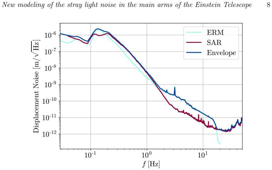
The carrying mechanism is the FFT-based Stationary Interferometer Simulations (SIS) code, now able to include baffles explicitly in the cavity propagation. For each baffle along the arm, the field from the input test mass is propagated to the baffle plane, clipped by the serrated inner aperture, and propagated to the end test mass, where it recombines with the main beam; this replaces the earlier solid-angle shielding approximation and lets diffraction at each edge feed power to downstream baffles. Two noise channels are assembled from these fields: diffraction noise, which in the frequency domain is $\tilde h_{\mathrm{df}}(f) = \sqrt{\lambda^2 + (8\Gamma P_{\mathrm{circ}}/cM\pi f^2)^2}\, X(f)/(\pi L)\, C$, with $C$ the sum over baffles of the overlap of the propagated fields integrated over each baffle surface; and backscatter noise, $\tilde h^2_{\mathrm{bs}}(f) = (1/L^2)[\lambda^2 + (8\Gamma P_{\mathrm{circ}}/cM\pi f^2)^2]\,(dP/d\Omega)_{\mathrm{bs}}\, X^2(f) K$, with $K = \sum_i z_i^{-2}(dP_i/d\Omega_{\mathrm{ms}})^2\,\delta\Omega_i^{\mathrm{ms}}$ encoding how much mirror-scattered light each baffle intercepts and sends back. The ground-motion input is an envelope of the 90% confidence seismic spectra measured at the two candidate sites, and the baffle displacement $X(f)$ is taken equal to the ground displacement at all frequencies (unit mechanical transfer), then upconverted into the 1–50 Hz band by phase wrapping. The quoted tolerances come from scanning offset, tilt, and absorber power and tracking $\min_f[\mathrm{SM}(f)/h(f)]$, the smallest distance between the one-tenth sensitivity safety margin and the predicted noise.
What would settle it
Measure the mechanical transfer function from ground motion to the baffle edge in a representative 50 m vacuum-tube section over 0.1–10 Hz; if the transfer magnitude exceeds unity enough to lift the predicted diffraction or backscatter noise above the 1/10 sensitivity margin at 2–6 Hz, the central conclusion fails. A complementary check would be a laboratory measurement of the serrated-edge diffraction pattern to validate the SIS clipping model, since diffraction is the dominant noise channel.
Extended reading notes
Core claim
The central claim is that the proposed baffle configuration keeps scattered-light noise subdominant in the Einstein Telescope main arms under nominal, ideal conditions, for both the triangular 10 km and L-shaped 15 km designs, and for both the high-frequency (ET-HF) and low-frequency (ET-LF) configurations. Using the FFT-based Stationary Interferometer Simulations (SIS) code, the field is now propagated through the actual baffle sequence, clipped at serrated apertures, and diffraction noise is computed numerically via the overlap integral $C = \sum_i \int E_{\mathrm{ITM}\to B_i} E_{B_i\to \mathrm{ETM}}\,dS$ over each baffle surface. Relative to the previous study, the predicted noise rises about 50% for ET-HF and falls about 30% for ET-LF, reflecting the corrected diffraction contribution, and in all nominal cases remains more than two orders of magnitude below the design sensitivity in the band where it is closest (2–5 Hz). The same machinery is then used to map what breaks this conclusion: radial beam offsets of $\Delta r \gtrsim 4$ cm (ET-HF) or $\gtrsim 7$ cm (ET-LF), tilts $\Delta\theta \gtrsim 8\times10^{-6}$ rad, or a single point absorber with $P_{\mathrm{abs}} > 100$ mW located at $r < 0.1$ m on the mirror all bring the noise up to the one-tenth safety margin at low frequencies. The paper's stated conclusion is that stray light does not limit ET in the ideal cavity, but beam alignment and mirror cleanliness are tight operational constraints.
Load-bearing premise
The calculation assumes the baffles move exactly as the ground at every frequency (unit mechanical transfer factor), so any real amplification or filtering by the baffle supports in the 0.1–10 Hz band would shift every quoted noise curve and every tolerance.
Editorial extensions
If this is right
- In the ideal, perfectly aligned cavity, the proposed baffle layout keeps scattered-light noise at least two orders of magnitude below the ET sensitivity at 2–5 Hz, for both the triangular 10 km and L-shaped 15 km layouts and for both ET-HF and ET-LF.
- The noise budget is dominated by diffraction at baffle edges, with backscatter roughly a factor 10 (ET-HF) or 4 (ET-LF) smaller, so edge diffraction is the channel to control first.
- The L-shaped 15 km arms carry about 100 more baffles per arm, lifting the noise; increasing the asymptotic baffle separation (e.g., from 50 m) would reduce both diffraction and backscatter noise, provided the vacuum pumping structures remain hidden from the mirrors.
- Beam offsets above 4 cm (ET-HF) or 7 cm (ET-LF) already meet the one-tenth safety margin near 5 Hz (ET-HF) or 3 Hz (ET-LF), so these are hard alignment tolerances for operation.
- Tilts at or above $8\times10^{-6}$ rad, or point absorbers with $P_{\mathrm{abs}} > 100$ mW inside $r < 0.1$ m, would compromise sensitivity at 2–6 Hz, meaning mirror cleanliness and alignment control are as important as baffle design.
Reading between the lines
- Because every noise curve is linear in the baffle displacement spectrum, the quoted tolerances scale inversely with the actual mechanical transfer of the baffle supports: a factor-two amplification of ground motion at 1–5 Hz would approximately halve the allowed offset and tilt before violating the safety margin.
- The study explicitly excludes stray light from the cryotrap regions and vacuum towers near the main mirrors; if those contributions are comparable to the arm noise, the total stray-light budget could be tighter than the paper's nominal conclusion.
- The same simulation pipeline could be used to test whether widening the baffle aperture or altering the serration profile relaxes the alignment tolerances, which is the redesign path the authors themselves suggest.
- The seismic envelope combines 90% confidence spectra from two candidate sites; if the final site's low-frequency ground motion is higher, the safety margin shrinks proportionally, so the 4–7 cm offset tolerances and 8 microradian tilt tolerance are tied to the site assumption.
Editorial analysis
A structured set of objections, weighed in public.
Referee Report
Summary. The paper presents updated simulations of stray-light noise in the main arms of the Einstein Telescope, for both the triangular 10 km and L-shaped 15 km configurations, using the FFT-based code SIS. The authors explicitly include baffles with serrated edges, compute diffraction noise numerically rather than with the earlier analytic formulas, and evaluate backscatter noise using simulated field distributions. Under nominal, perfectly centered beam conditions they find that the scattered-light noise is more than two orders of magnitude below the ET sensitivity in the 2–5 Hz band, and therefore does not limit the design. For the triangular configuration they also study non-ideal conditions: transverse beam offsets, beam tilts, and point absorbers on the mirrors, and derive operational constraints (offsets above about 4 cm for ET-HF and 7 cm for ET-LF, tilts above about 8e-6 rad, and point absorbers with more than 100 mW absorbed power within 0.1 m of the mirror center would compromise the sensitivity at 2–6 Hz). The paper states that the baffle motion is assumed to follow the ground motion with a transfer function equal to one, and that a more realistic mechanical model is deferred to future design work.
Significance. If the results are correct, the paper provides the most detailed stray-light noise estimate for ET to date and, crucially, translates a simulated noise budget into design and operational tolerances for beam alignment and mirror cleanliness. The explicit simulation of baffles, serrations, and numerical diffraction is a clear step beyond the previous analytic treatment, and the use of a measured ground-motion envelope from two candidate sites adds realism. The central qualitative conclusion — that stray light is not limiting in the ideal cavity — has a comfortable margin. However, the quantitative thresholds in Sections 4 and 5 are load-bearing for the design and are derived under assumptions that the authors themselves acknowledge to be uncertain, in particular the baffle-to-ground transfer function. The paper would benefit from a sensitivity analysis and from a validation of the numerical diffraction calculation.
major comments (3)
- [Sec. 2.4] The assumption that the baffle motion exactly follows the ground motion, i.e., a mechanical transfer function H(f)=1 at all frequencies, is load-bearing for all noise estimates because both Eq. (2) and Eq. (5) are proportional to |X(f)|^2 and hence to |H(f)|^2. In Sec. 3 the nominal margin is quoted as 'at least two orders of magnitude' below the sensitivity in the 2–5 Hz band; combined with the 1/10 safety margin used in Sec. 4, this leaves only about a factor of 10 in displacement amplitude before the safety margin is touched. Any resonance or amplification in the baffle suspension or vacuum-tube structure in the 0.1–10 Hz band could therefore erase the safety margin and shift all the thresholds quoted in Sec. 4. The paper explicitly notes that a realistic description 'requires a mature implementation of the designs' and that these are 'currently partially unknown' — this is an honest statement, but it makes the central quantitative claims conditional on an unverified assumption. I request a parametric study that varies a low-frequency amplification factor (or a simple single-resonance model) and shows how the nominal margin and the thresholds in Sec. 4 change, or, at minimum, an explicit statement that all quantitative thresholds assume H(f)=1 and could be violated by modest mechanical amplification.
- [Sec. 4 and Sec. 5] The quoted operational limits (dr > 4 cm for ET-HF and 7 cm for ET-LF, dtheta >= 8e-6 rad, P_abs > 100 mW within r < 0.1 m) are presented as precise values, but the paper provides no error bars or propagation of input uncertainties. The input parameters — baffle BRDF, mirror roughness maps, the seismic envelope, and the cavity parameters in Tables 1 and 2 — all carry uncertainties, some of which are not quantified. In addition, the thresholds are defined by the min_f(SM(f)/h(f)) crossing of an arbitrary 1/10 safety margin; changing the safety margin from 1/10 to, say, 1/20 or 1/5 would shift the thresholds. The K and C factors in Eqs. (6) and (3) are simulation outputs whose statistical and systematic uncertainties are not reported. I recommend adding a sensitivity analysis or, at least, a discussion of how the quoted thresholds would change under reasonable variations of the dominant inputs (e.g., a factor of two in baffle BRDF or in the seismic envelope). Without this, the thresholds are likely to be over-interpreted by the ET design team.
- [Sec. 2.2 and Sec. 3] The new numerical diffraction calculation is a central improvement claimed in the paper, but it is not validated in the manuscript. The authors state that SIS 'does not use any of the analytical relations' and quote results that differ from the previous analytic calculation of Ref. [28] by about +50% (ET-HF) and -30% (ET-LF), yet no comparison is shown against Eq. (1) in a simplified test geometry, and no convergence test or resolution check for the FFT grid is described. Since the C factor in Eq. (3) enters the diffraction noise directly, and since the paper argues that the new numerical treatment is more accurate, the reader cannot tell whether the change in the predicted noise is due to the improved physics (baffle clipping, serrations) or to numerical artifacts. I recommend adding a validation subsection that compares the SIS result with the analytic formula for a simple case (e.g., a single baffle without serrations) and demonstrates convergence with grid size and number of propagated modes.
minor comments (5)
- [Abstract and Sec. 1] The abstract and introduction use 'supersede previous studies' without specifying which previous results are changed and by how much; this information appears only later in Sec. 3. A sentence in the introduction summarizing the magnitude of the changes (e.g., +50% / -30%) would help the reader.
- [Figures 3 and 4] The legend entries 'Backscattering Ba0es' and 'Di,raction' contain typographical artifacts. The same issue appears in the captions of Figures 5–8 where '7rad' and 'µrad' are inconsistently formatted. These should be corrected before publication.
- [Sec. 2.3, Eq. (6)] The definition of K in Eq. (6) uses dP_i/dOmega_ms, which is estimated from the simulation via Eq. (7). This is a reasonable approach, but the finite resolution of the grid and the use of the BRDF tail are not described with enough detail for the reader to reproduce the calculation. A reference to the relevant SIS documentation (Ref. [29]) is good, but the paper could mention the specific angular cutoff where the analytical BRDF tail takes over.
- [Sec. 2.4 and Fig. 2] The seismic envelope is described as the 90% confidence level envelope of the two site spectra. It would be helpful to state whether the envelope is the pointwise maximum of the two spectra or the upper bound of the combined set, and to indicate how the 90% confidence is computed (e.g., per frequency bin over time). This is a minor clarity issue but affects the interpretation of 'conservative.'
- [Sec. 4.3] The point absorber study assumes a single absorber on the ETM only and uses the same radiative-pressure coupling as for the distributed scattering. The justification for this extension is not explicitly discussed, and the effect of multiple absorbers or absorber location relative to the beam waist is not considered. A brief comment on why the single-absorber scenario captures the essential physics would be useful.
Circularity Check
No significant circularity: the stray-light noise curves are computed from first-principles FFT field propagation with external design and seismic inputs, not from the target sensitivity curves.
full rationale
The paper's derivation chain is self-contained and benchmarked, not circular. The noise estimates in Eqs. (2) and (5) are computed from simulated optical fields (C and K factors) using standard diffraction and backscatter formalisms, with input parameters taken from ET design documents and prior external studies (Tables 1 and 2). The ground-motion input is an envelope of measured seismic data from the two candidate sites, and the mechanical transfer factor of unity is an openly stated assumption, explicitly acknowledged as provisional pending mature designs (Sec. 2.4); this is a modeling limitation, not a circular step, because no target noise level is used to set that assumption. The comparison against the ET sensitivity curve and the 1/10 safety margin is a benchmark, and the offset, tilt, and absorber thresholds in Sec. 4 are derived from the same first-principles simulation, not fitted to the sensitivity curve. The self-citation of Ref. [28] provides the baffle apertures and layout as a design input from prior published work by overlapping authors, but this is not load-bearing in the sense of forbidding alternatives or supplying a uniqueness theorem; the new noise calculations explicitly supersede and improve on that prior study rather than assuming its conclusions. No fitted parameter is renamed as a prediction, and no equation reduces to its own input by construction. Therefore the circularity score is 0.
Assumptions & free parameters
free parameters (3)
- Baffle BRDF (dP/dOmega_bs) =
1e-4 sr^-1
- Mirror surface roughness maps =
Virgo O5 mirror maps
- Asymptotic baffle separation and aperture layout =
50 m separation; apertures inherited from Ref. [28]
assumptions (7)
- ad hoc to paper Baffle displacement equals ground displacement with transfer factor one at all frequencies.
- domain assumption The reciprocity relation connects light scattering into and out of the main beam.
- domain assumption The radiation-pressure coupling formula, Eq. (2), from Refs. [28,30] applies to the ET cavities.
- domain assumption Baffle surfaces scatter with BRDF 10^-4 sr^-1.
- domain assumption Virgo O5 mirror maps, supplemented by a BRDF tail model, describe ET mirror scattering.
- domain assumption The seismic envelope of 90% confidence measured spectra is a conservative worst-case input.
- domain assumption The SIS simulation code correctly implements FFT propagation, clipping, and serrated baffle diffraction.
Cite this review
Pith. "Pith review of New modeling of the stray light noise in the main arms of the Einstein Telescope." pith.science (2026). https://pith.science/paper/EG2ZE7D4
@misc{pith2026250618083,
  author       = {Pith},
  title        = {Pith review of: New modeling of the stray light noise in the main arms of the Einstein Telescope},
  year         = {2026},
  howpublished = {\url{https://pith.science/paper/EG2ZE7D4}},
  note         = {Machine review of arXiv:2506.18083}
}
read the original abstract
Stray light represents a significant noise source for gravitational wave detectors, requiring an accurate modeling and mitigation to preserve the experiment's sensitivity. In this article, we present an updated and improved analysis of the stray-light induced noise in the Einstein Telescope main arm. The results presented here supersede previous studies taking into account a number of improvements, including baffle clipping effects, new numerical calculations for computing diffraction contributions and the influence of baffle edge serrations. Results are presented for both triangular and L-shaped configurations for the experiment. Furthermore, in the case of the triangular configuration, we examine non-ideal optical cavity conditions, such as beam offsets and misalignments, and the presence of point absorbers in the mirrors, which can increase scattered light noise. This can be translated into future stringent constraints on the design and operating parameters of the interferometer, thus facilitating to achieve its sensitivity targets.
Figures


Figures from the paper (7 more)


Forward citations
Cited by 1 Pith paper
-
Optomechanical transfer factors for scattered light noise estimations in the beamtubes of ground-based gravitational wave detectors
Scattered-light noise coupling to strain readout is derived as full optomechanical transfer factors, recovering legacy models only in phase-dominated regimes and substantially revising Einstein Telescope low-frequency...
Reference graph
Works this paper leans on
-
[28]
Andr´ es-Carcasona M, Macquet A, Mart ´ ınez M, Mir L M and Yamamoto H 2023 Phys. Rev. D108102001 (Preprint2307.14104)
work page Pith review arXiv 2023
-
[1]
Accadia Tet al.2010Class. Quant. Grav.27194011
-
[2]
Fiori Iet al.2020Galaxies882
-
[3]
Was M, Gouaty R and Bonnand R 2021Class. Quant. Grav.38075020 (Preprint 2011.03539)
work page Pith review arXiv 2011
-
[4]
Soni Set al.(LIGO) 2020Class. Quant. Grav.38025016 (Preprint2007.14876)
-
[5]
Longo A, Bianchi S, Plastino W, Arnaud N, Chiummo A, Fiori I, Swinkels B and Was M 2020Class. Quant. Grav.37145011 (Preprint2002.10529)
-
[6]
Longo A, Bianchi S, Valdes G, Arnaud N and Plastino W 2022Class. Quant. Grav. 39035001 (Preprint2112.06046)
-
[7]
Longo A, Bianchi S, Valdes G, Arnaud N and Plastino W 2024Class. Quant. Grav. 41015004
Show all 48 references
-
[8]
Andr´ es-Carcasona Met al.2023Phys. Rev. D107062001 (Preprint2210.16313)
-
[9]
Andr´ es-Carcasona M, Mart ´ ınez M, Mir L M, Mundet J and Yamamoto H 2025 Phys. Rev. D111042001 (Preprint2412.11592)
2025 arXiv
-
[10]
Macquet A, Andr´ es-Carcasona M, Martinez M, Mir L M, Romero-Rodriguez A and Yamamoto H 2023Class. Quant. Grav.40077001 (Preprint2210.16308)
-
[11]
Romero-Rodr ´ ıguez A, Allocca A, Chiummo A, Mart ´ ınez M, Mir L M and Yamamoto H 2021Class. Quant. Grav.38045002 (Preprint2008.13740)
-
[12]
Romero-Rodr ´ ıguez A, Mart ´ ınez M, Mir L M and Yamamoto H 2022Galaxies10 86
-
[13]
Ballester Oet al.2022Class. Quant. Grav.39115011 (Preprint2111.09312)
-
[14]
Bianchi S, Longo A, Valdes G, Gonz´ alez G and Plastino W 2022Class. Quant. Grav.39195005 (Preprint2107.07565) REFERENCES19
-
[15]
Vinet J Y, Brisson V and Braccini S 1996Phys. Rev. D54(2) 1276–1286
-
[16]
Vinet J, Brisson V, Braccini S, Ferrante I, Pinard L, Bondu F and Tourni´ e E 1997 Phys. Rev. D56(10) 6085–6095
1997
-
[17]
Brisson V and Vinet J 1998 Summary of scattered light noise calculations and baffle design in the long cavities Tech. Rep. VIR-NOT-LAL-1390-123 VIRGO
1998
-
[18]
Thorne K 1989 Light Scattering and Proposed Baffle Configuration for the LIGO Tech. Rep. LIGO-T890017-00 LIGO
1989
-
[19]
Flanagan E and Thorne K 1995 Light Scattering and Baffle Configuration for LIGO Tech. Rep. LIGO-T950101-00 LIGO
1995
-
[20]
Flanagan E and Thorne K 1994 Noise Due to Backscatter Off Baffles, the Nearby Wall, and Objects at the Fare End of the Beam Tube; and Recommended Actions Tech. Rep. LIGO-T940063-00-R LIGO
1994
-
[21]
Flanagan E and Thorne K 1995 Scattered-Light Noise for LIGO Tech. Rep. LIGO- T950033-00 LIGO
1995
-
[22]
ET science team 2011 Einstein gravitational wave telescope conceptual design study Tech. Rep. ET-0106C-10 ET
2011
-
[23]
ET steering committee 2020 ET design report update 2020 Tech. Rep. ET-0007B-20 ET
2020
-
[24]
Abbott B Pet al.(LIGO Scientific Collaboration) 2017Class. Quant. Grav.34 044001 (Preprint1607.08697)
-
[25]
Reitze Det al.2019Bull. Am. Astron. Soc.51141 (Preprint1903.04615)
-
[26]
Reitze Det al.2019Bull. Am. Astron. Soc.51035 (Preprint1907.04833)
-
[27]
Abac Aet al.2025arXiv(Preprint2503.12263)
-
[29]
Romero A and Yamamoto H 2024 SIS20 documents Tech. Rep. LIGO-T2000311-v7 LIGO
2024
-
[30]
Fritschel P and Yamamoto H 2013 Scattered light noise due to the ETM coating ripple Tech. Rep. LIGO-T1300354 LIGO
2013
-
[31]
Measurement and analysis(SPIE Press)
Stover J C 2012Optical scattering. Measurement and analysis(SPIE Press)
-
[32]
Yamamoto H 2011 1D PSD of mirror maps Tech. Rep. LIGO-T1100353 LIGO
2011
-
[33]
Express208329–8336
Ottaway D J, Fritschel P and Waldman S J 2012Opt. Express208329–8336
-
[34]
Chua S S Yet al.2014Class. Quant. Grav.31035017 (Preprint1307.8176)
-
[35]
Naticchioni Let al.2014Class. Quant. Grav.31105016
-
[36]
Naticchioni Let al.2020J. Phys. Conf. Ser.1468012242
-
[37]
Di Giovanni M,et al.2021Seismological Research Letters92352–364
-
[38]
Allocca A, Berbellini A, Boschi L, Calloni E, Cardello G L, Cardini A, Carpinelli M, Contu A, D’onofrio L, D’Urso Det al.2021Eur. Phys. J. Plus136511 REFERENCES20
-
[39]
Saccorotti G, Giunchi C, D’Ambrosio M, Gaviano S, Naticchioni L, D’Urso D, Rozza D, Cardini A, Contu A, Dordei Fet al.2023Eur. Phys. J. Plus138793
-
[40]
Di Giovanni M, Giunchi C, Saccorotti G, Berbellini A, Boschi L, Olivieri M, De Rosa R, Naticchioni L, Oggiano G, Carpinelli Met al.2021Seismological Society of America92352–364
-
[41]
Di Giovanni M, Koley S, Ensing J, Andric T, Harms J, D’Urso D, Naticchioni L, De Rosa R, Giunchi C, Allocca Aet al.2023Geophysical Journal International 2341943–1964
1964
-
[42]
Koley S, Bader M, van den Brand J, Campman X, Bulten H J, Linde F and Vink B 2022Class. Quant. Grav.39025008
-
[43]
Koley S, Bulten H J, van den Brand J, Bader M, Linde F and Beker M 2019First Break3783–90
-
[44]
Bader M, Koley S, van den Brand J, Campman X, Bulten H J, Linde F and Vink B 2022Class. Quant. Grav.39025009
-
[45]
Zhang T, Danilishin S and Korobko M 2025 Conceptual Design and Noise Budget of Einstein Telescope Tech. Rep. ET-0007C-23 ET
2025
-
[46]
Jia Wet al.2021Phys. Rev. Lett.127241102 (Preprint2109.08743)
-
[47]
Opt.604047–4063 (Preprint 2101.05828)
Brooks A Fet al.(LIGO Scientific) 2021Appl. Opt.604047–4063 (Preprint 2101.05828)
-
[48]
Buikema Aet al.(aLIGO) 2020Phys. Rev. D102062003 (Preprint2008.01301)
Reviewed August 6, 2026 · model on record in the stance chip above.
Discussion (0). Sign in to comment.