REVIEW 3 major objections 4 minor 35 references
Unbiased higher-order frictional contact using midplane and patch based segment-to-segment penalty method
T0 review · 3 major / 4 minor · reviewed 2026-08-07 · deepseek-v4-flash
Pith's one-line read This paper claims that frictional contact between curved surfaces can be computed in a single pass, without designating one body as master, by penalising interpenetration and sliding across a midplane built between subdivided quadratic…
desk verdict A useful, honest extension of the authors' midplane contact method to quadratic hexahedra; the benchmarks support the main claim, but the acknowledged subfacet mapping error is never quantified. read the letter →
The pith
A machine-rendered reading of the paper's core claim, the machinery that carries it, and where it could break.
The reading
What carries the argument
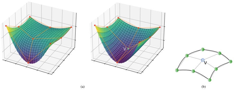
The load-bearing object is the midplane built between pairs of bilinear subfacets: each quadratic facet is subdivided into four flat subfacets, and each interpenetrating subfacet pair defines its own flat midplane whose normal carries the penalty tractions. Two auxiliary constructions do the actual work: an inverse bilinear mapping locates each Gaussian quadrature point on the projected subfacets, and an affine re-parameterisation (eq. 14) lifts those coordinates into the parametric space of the true quadratic facet, where the interpenetration gap is evaluated with the full shape functions. A one-shot midplane correction (eq. 15) re-orients the midplane using the surface normals of both physical facets at the centroid of the interpenetration volume. Friction is handled by a predictor-corrector return mapping on the midplane, and a beta factor (eqs. 19-20) distributes the tangential traction over all nine nodes of each contacting facet.
What would settle it
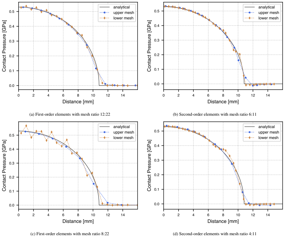
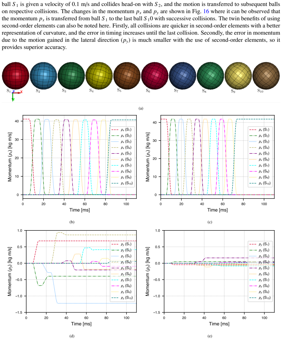
Recompute one of the paper's curved-contact benchmarks, such as the Hertzian contact with the coarser 4:11 mesh ratio or the sphere collision, using the same code but replacing the affine subfacet-to-facet mapping with an iterative normal projection of each quadrature point onto the true quadratic surface; if the pressure profile, the contact zone size, or the exchanged momentum changes visibly, that demonstrates where the bilinear-subfacet approximation breaks.
Extended reading notes
Core claim
The paper's central claim is that segment-to-segment contact for higher-order finite elements can be made accurate, frictional, and unbiased in a single pass by constructing a midplane between pairs of subfacets obtained from subdividing quadratic facets. Each nine-noded facet is split into four bilinear subfacets, yielding up to 4x4 subfacet-to-subfacet pairs per contacting facet pair; normal traction penalises the true interpenetration gap measured between the physical curved surfaces at quadrature points, while frictional traction penalises relative sliding between subfacet pairs over their shared patch on the midplane using a predictor-corrector return mapping. The midplane itself can be re-tilted once so that it follows the local curvature of both interacting surfaces at the centroid of the interpenetration volume. The paper maintains that this formulation passes the contact patch test at the accuracy of the underlying finite elements, produces smoother Hertzian contact pressure than first-order meshes with equal node counts, and improves the timing and direction of momentum exchange in elastic collisions, fill rotation, self-contact, and inelastic collision.
Load-bearing premise
The whole method depends on the flat bilinear subfacets, plus one midplane tilt correction, being a faithful enough guide to the position of the truly curved quadratic surfaces; if the affine mapping mis-locates quadrature points, the computed gaps and forces are biased even though the formulation is nominally unbiased.
Editorial extensions
If this is right
- Contact patch tests transfer uniform pressure at the accuracy of the underlying finite elements, so the algorithm introduces no bias at flat, conforming interfaces.
- For curved interfaces with the same degrees of freedom, quadratic meshes suppress the oscillating contact pressure that first-order meshes produce, and the advantage grows as the contacting meshes become more non-conforming.
- Dynamic collisions between curved bodies exchange momentum more accurately and on time, because curvature-preserving surfaces avoid the material loss and delayed detection that plague first-order meshes.
- Because the method is single-pass and unbiased, it handles self-contact and large-deformation folding without spurious directional bias, as shown in the tube-crushing and frictional self-contact tests.
- The same midplane-and-patch framework extends to serendipity elements via a virtual centre node, and the authors state it can transfer to isogeometric analysis.
Reading between the lines
- The paper tests only one midplane correction; iterating the tilt update would plausibly squeeze out the residual directional error that remains in strongly curved dynamic contact, and this is directly measurable in the collision tests.
- The paper's own interpolation-error analysis implies an accuracy floor: once facet curvature is strong enough to bend the quadratic parametric lines, further h-refinement of the mesh cannot improve contact accuracy because the contact integral itself is polluted by the affine subfacet mapping.
- Replacing the affine lift with an iterative normal projection onto the true quadratic surface, which the authors name as the remedy, would remove the dominant error source at the cost of a local Newton iteration per quadrature point; that variant is a natural, testable follow-up.
Editorial analysis
A structured set of objections, weighed in public.
Referee Report
Summary. The manuscript presents a single-pass, penalty-based segment-to-segment contact formulation for higher-order (27-noded hexahedral) finite elements. Each 9-noded quadratic contact facet is subdivided into four bilinear subfacets; contact is enforced pairwise on subfacet-to-subfacet pairs through a midplane between linearized subfacets. Normal traction is computed by penalizing the interpenetration gap integrated over the intersection polygon of the two subfacet projections, with an optional one-iteration midplane tilt correction (Eq. 15). Tangential traction follows a predictor-corrector Coulomb law with a return mapping and a beta-scaling to distribute nodal friction forces (Eqs. 16-20). The method is demonstrated on a contact patch test, Hertzian contact, elastic collisions of spheres, a rotating fill in a cylinder, frictional sliding, oblique ring collision, self-contact, and inelastic bar collision, comparing 27-node elements with 8-node elements having the same number of nodes. The central claim is that the higher-order formulation yields smoother and more accurate contact tractions and momentum exchange than first-order elements for curved geometries, while remaining unbiased and single-pass.
Significance. If the claims are substantiated, the work would be a useful extension of unbiased midplane-based STS contact to quadratic elements, potentially improving contact pressure accuracy and dynamic momentum transfer in explicit codes using Hex27 elements. The paper's strengths include a clear algorithmic description (Algorithm 1), a wide set of challenging test cases including self-contact and inelastic collision, and an explicit acknowledgment of the approximation error in subfacet linearization (Section 3.4). The patch test result is particularly convincing: flat-contact accuracy is shown to match the underlying element interpolation. However, as detailed in the major comments, the quantitative support for the higher-order accuracy claim and the frictional model is incomplete, and a sign inconsistency in the gap definition would need to be resolved before the method can be reproduced or fully assessed.
major comments (3)
- [3.4 and 6.2] Section 3.4 explicitly acknowledges that the affine mapping from the bilinear subfacets to the quadratic facet parameter space (Eq. 14) is approximate and 'eventually leads to inaccuracies in the contact integral and the evaluated normal nodal forces.' This is a load-bearing concern because the central claim of the paper is that the higher-order formulation provides highly accurate contact traction on curved surfaces. However, no quantitative error norm is provided to bound this error for strongly curved or distorted elements, and the Hertzian contact results in Section 6.2 (Figs. 11 and 12) are only compared visually with the analytical solution. Please add a quantitative error assessment, for example an L2 or maximum error in contact pressure versus the Hertz solution, and a test with a strongly curved interface or distorted mesh that isolates the affine-mapping error.
- [3.3, Eqs. (19)-(20), and 6.5] The beta-scaling in Eqs. (19)-(20) is central to the frictional nodal force distribution, but it is introduced without derivation and the area A in Eq. (20) is never defined. The frictional sliding benchmark in Section 6.5 is qualitative only: it shows a plausible hysteresis loop but provides no reference solution for the expected nonlinear nodal force distribution on a second-order element. Since Coulomb friction with return mapping plus the beta-scaling is an additional modeling assumption beyond the standard penalty STS framework, please derive the scaling from a consistent virtual-work argument or validate it against an analytical or converged reference solution.
- [3.1, Eq. (13), and Algorithm 1] The sign convention for the normal gap is inconsistent. Section 3.1 defines the normal traction as proportional to gN H(-gN), implying that gN < 0 corresponds to penetration. Eq. (13) defines gN = g2_N - g1_N, whereas Algorithm 1 (line 12) defines gN = g1_N + g2_N, and line 14 treats gN < 0 as 'no interpenetration.' These statements cannot all be correct. Please reconcile the sign convention and provide a precise definition of gN, since the normal contact integral (Eqs. 10-11) depends directly on this quantity.
minor comments (4)
- [1] There is a typo in the first paragraph: 'multibody sytems' should be 'multibody systems.'
- [3.1, Eq. (12)] The projection operator Proj_{γmp} used to define the parametric coordinates (ξ_i_1, ξ_i_2) is not defined; please state explicitly how the projection onto the midplane is computed.
- [3.2] The midplane correction is applied only once, although the text notes that it can be continued iteratively; the effect of further iterations on accuracy is not studied.
- [5] The extension to serendipity elements is described only conceptually; providing at least one simple numerical example would strengthen the claim of versatility.
Circularity Check
No significant circularity: the midplane STS framework is extended from the authors' own prior works [26,27] and the inverse mapper [31], but the present paper re-validates the framework against external Hertz, patch-test, and momentum benchmarks; the Section 3.4 affine-mapping error is an acknowledged limitation, not a circular step.
full rationale
The derivation chain is self-contained against external references. Normal traction is the penalisation of a geometrically computed interpenetration gap (Eqs. 10-13) at quadrature points located via projections of subfacets onto the midplane; frictional traction is a predictor-corrector penalisation of relative sliding with Coulomb return mapping (Eqs. 16-18). No penalty parameter is fitted to any quantity that the paper later 'predicts': fs is varied per test as a standard scaling study (Figs. 11-12), and changing it degrades accuracy in the expected direction, so it is not tuned to force agreement. The core architecture (midplane-based single-pass unbiased STS with uniform penalty) is genuinely imported from the authors' own [26,27], and the inverse bilinear mapping from [31]; these self-citations are load-bearing for the base framework. They do not, however, make the paper circular, because the present claims are independently supported: the contact patch test transfers uniform pressure across non-matching meshes, the Hertzian test is compared with the analytical solution for curved quadratic facets, and the collision and self-contact tests are governed by physical momentum and deformation behaviour rather than by the cited results. Under the review rule, externally falsifiable benchmarks inside the paper constitute independent support for the self-cited base method. The paper itself flags the accuracy limit of its affine subfacet mapping in Section 3.4 ('using first-order subfacet and the subsequent affine mapping results in an error when evaluating the parametric coordinates of the required point on the physical facets. This eventually leads to inaccuracies in the contact integral and the evaluated normal nodal forces') and repeats the caution in the Conclusion; this is a correctness and error-bound concern for strongly curved or distorted elements (no quantitative error norm is supplied), not a circularity, since no equation reduces by construction to its input. Score 1 reflects the heavy but non-circular self-citation of the base framework.
Assumptions & free parameters
free parameters (2)
- Normal penalty scaling factor, f_s =
10 (patch, Hertz), 5, 1 (Hertz), 1 (collisions), 3.5 (tube crush)
- Tangential penalty, epsilon_T =
10 (frictional sliding, self-contact)
assumptions (5)
- domain assumption Subdivision of a 9-noded quadratic facet into four bilinear subfacets, plus affine mapping (eq. 14), locates quadrature points on the midplane with acceptable accuracy.
- domain assumption The contact region between two curved subfacets is the intersection polygon of their projections onto a flat midplane.
- domain assumption One midplane correction using the centroid of interpenetration (eq. 15) sufficiently recovers local curvature.
- ad hoc to paper Coulomb friction with return mapping and the beta-scaling (eq. 20) yields correct nodal friction distribution.
- domain assumption Penalty with epsilon_N = min(bulk moduli) is a sufficient contact constraint for the presented tests.
Cite this review
Pith. "Pith review of Unbiased higher-order frictional contact using midplane and patch based segment-to-segment penalty method." pith.science (2026). https://pith.science/paper/BZBQG37U
@misc{pith2026250621767,
  author       = {Pith},
  title        = {Pith review of: Unbiased higher-order frictional contact using midplane and patch based segment-to-segment penalty method},
  year         = {2026},
  howpublished = {\url{https://pith.science/paper/BZBQG37U}},
  note         = {Machine review of arXiv:2506.21767}
}
read the original abstract
A highly accurate, single-pass, unbiased frictional contact algorithm for higher-order elements based on the concept of midplane is presented. Higher-order elements offer a lucrative choice for contact problems as they can better represent the curvature of original geometries compared to the first-order elements. Compressive and frictional contact constraints are applied over the contact pairs of sub-segments obtained by the subdivision of higher-order segments. The normal traction depends upon the penalisation of true interpenetration, and frictional traction depends upon relative sliding between sub-segments over their shared patches. The midplane constructed by linearised subfacets can be corrected to account for local curvature of interacting physical surfaces. Demonstrated through multiple tests, the use of higher-order elements surpasses the accuracy of first-order elements for curved geometries. Its versatility extends from static to dynamic conditions for flat and curved interfaces including frictional contact. The presented examples include contact patch test, Hertzian contact, elastic collision, rotation of concentric surfaces, frictional sliding, self-contact and inelastic collision problems. Here, contact patch test matches the accuracy of finite elements and Hertzian contact shows smoother solution compared to first-order meshes. The elastic collision problem highlights the utility of the algorithm in accurate prediction of configuration changes in multibody systems. The frictional sliding demonstrates the ability to represent the expected nonlinear distribution of nodal forces for the higher-order elements. The large deformation problems, e.g. self-contact and inelastic collision, specifically benefit from the accuracy in surface representation using higher-order discretisation and continuous contact constraint imposition on such surfaces during deformation.
Figures


Figures from the paper (21 more)








Reference graph
Works this paper leans on
-
[1]
R. S. Browning, K. T. Danielson, D. L. Littlefield, Second-order pyramid element formulations suitable for lumped-mass explicit methods in nonlinear solid mechanics, Computer Methods in Applied Mechanics and Engineering 405 (2023) 115854. doi:10.1016/j.cma.2022. 115854
-
[2]
M. A. Puso, T. A. Laursen, J. Solberg, A segment-to-segment mortar contact method for quadratic elements and large deformations, Computer Methods in Applied Mechanics and Engineering 197 (6) (2008) 555–566. doi:10.1016/j.cma.2007.08.009
-
[3]
A. Popp, B. I. Wohlmuth, M. W. Gee, W. A. Wall, Dual Quadratic Mortar Finite Element Methods for 3D Finite Deformation Contact, SIAM Journal on Scientific Computing 34 (4) (2012) B421–B446. doi:10.1137/110848190
-
[4]
K. T. Danielson, Curved node-to-face contact schemes for higher-order finite elements in lumped-mass explicit methods, Computer Methods in Applied Mechanics and Engineering 395 (2022) 115056. doi:10.1016/j.cma.2022.115056
arXiv 2022
-
[5]
T. J. Hughes, R. L. Taylor, W. Kanoknukulchai, A finite element method for large displacement contact and impact problems, Formulations and computational algorithms in FE analysis (1977) 468–495
work page 1977
-
[6]
J. O. Hallquist, NIKE2D: An implicit, finite-deformation, finite-element code for analyzing the static and dynamic response of two- dimensional solids, Tech. rep., California Univ., Livermore (USA). Lawrence Livermore Lab. (1979)
work page 1979
-
[7]
R. L. Taylor, P. Papadopoulos, On a patch test for contact problems in two dimensions, Computational methods in nonlinear mechanics 690 (1991) 702
work page 1991
-
[8]
M. A. Puso, T. A. Laursen, A mortar segment-to-segment contact method for large deformation solid mechanics, Computer Methods in Applied Mechanics and Engineering 193 (6) (2004) 601–629. doi:10.1016/j.cma.2003.10.010
Show all 35 references
-
[9]
Bernardi, N
C. Bernardi, N. Debit, Y . Maday, Coupling finite element and spectral methods: First results, Mathematics of Computation 54 (189) (1990) 21–39. doi:10.1090/S0025-5718-1990-0995205-7
1990 doi
-
[10]
M. A. Puso, T. A. Laursen, A mortar segment-to-segment frictional contact method for large deformations, Computer Methods in Applied Mechanics and Engineering 193 (45) (2004) 4891–4913. doi:10.1016/j.cma.2004.06.001
2004 doi
-
[11]
R. P. Carvalho, A. M. C. Carneiro, F. M. A. Pires, A. Popp, An e fficient algorithm for rigid/deformable contact interaction based on the dual mortar method, Computational Mechanics (Oct. 2022). doi:10.1007/s00466-022-02226-2
2022 doi
-
[12]
K. A. Fischer, P. Wriggers, Mortar based frictional contact formulation for higher order interpolations using the moving friction cone, Computer Methods in Applied Mechanics and Engineering 195 (37) (2006) 5020–5036. doi:10.1016/j.cma.2005.09.025. 26
2006 doi
-
[13]
B. Yang, T. A. Laursen, X. Meng, Two dimensional mortar contact methods for large deformation frictional sliding, International Journal for Numerical Methods in Engineering 62 (9) (2005) 1183–1225. doi:10.1002/nme.1222
2005 doi
-
[14]
M. Tur, F. J. Fuenmayor, P. Wriggers, A mortar-based frictional contact formulation for large deformations using Lagrange multipliers, Computer Methods in Applied Mechanics and Engineering 198 (37) (2009) 2860–2873. doi:10.1016/j.cma.2009.04.007
2009 doi
-
[15]
T. W. McDevitt, T. A. Laursen, A mortar-finite element formulation for frictional contact problems, International Journal for Numerical Methods in Engineering 48 (10) (2000) 1525–1547. doi:10.1002/1097-0207(20000810)48:10<1525::AID-NME953>3.0.CO;2-Y
2000 doi
-
[16]
M. A. Puso, A 3D mortar method for solid mechanics, International Journal for Numerical Methods in Engineering 59 (3) (2004) 315–336. doi:10.1002/nme.865
2004 doi
-
[17]
Steimer, M
C. Steimer, M. Mayr, A. Popp, Targeting a faster time-to-solution of mortar-based contact problems, PAMM (2023) e202300157 doi:10. 1002/pamm.202300157
2023
-
[18]
A. Popp, M. Gitterle, M. W. Gee, W. A. Wall, A dual mortar approach for 3D finite deformation contact with consistent linearization, International Journal for Numerical Methods in Engineering 83 (11) (2010) 1428–1465. doi:10.1002/nme.2866
2010 doi
-
[19]
Gitterle, A
M. Gitterle, A. Popp, M. W. Gee, W. A. Wall, Finite deformation frictional mortar contact using a semi-smooth Newton method with consistent linearization, International Journal for Numerical Methods in Engineering 84 (5) (2010) 543–571. doi:10.1002/nme.2907
2010 doi
-
[20]
A. Popp, W. A. Wall, Dual mortar methods for computational contact mechanics – overview and recent developments, GAMM-Mitteilungen 37 (1) (2014) 66–84. doi:10.1002/gamm.201410004
2014 doi
-
[21]
D. Liu, S. J. van den Boom, A. Simone, A. M. Arag´on, An interface-enriched generalized finite element formulation for locking-free coupling of non-conforming discretizations and contact, Computational Mechanics 70 (3) (2022) 477–499. doi:10.1007/s00466-022-02159-w
2022 doi
-
[22]
Konyukhov, K
A. Konyukhov, K. Schweizerhof, Incorporation of contact for high-order finite elements in covariant form, Computer Methods in Applied Mechanics and Engineering 198 (13) (2009) 1213–1223. doi:10.1016/j.cma.2008.04.023
2009 doi
-
[23]
Padmanabhan, T
V . Padmanabhan, T. A. Laursen, A framework for development of surface smoothing procedures in large deformation frictional contact analysis, Finite Elements in Analysis and Design 37 (3) (2001) 173–198. doi:10.1016/S0168-874X(00)00029-9
2001 doi
-
[24]
K. T. Danielson, J. L. O’Daniel, Reliable second-order hexahedral elements for explicit methods in nonlinear solid dynamics, International Journal for Numerical Methods in Engineering 85 (9) (2011) 1073–1102. doi:10.1002/nme.3003
2011 doi
-
[25]
K. T. Danielson, M. D. Adley, T. N. Williams, Second-order finite elements for Hex-Dominant explicit methods in nonlinear solid dynamics, Finite Elements in Analysis and Design 119 (2016) 63–77. doi:10.1016/j.finel.2016.02.008
2016 doi
- [26]
-
[27]
I. Sahu, N. Petrinic, Patch based unbiased 3D frictional contact formulation for finite element algorithms, Computer Methods in Applied Mechanics and Engineering 441 (2025) 117958. doi:10.1016/j.cma.2025.117958
2025
-
[28]
Bathe, KJ Bathe – Finite Element Procedures, 2nd Edition, Prentice-Hall, Englewood Cli ffs, N.J, 2014
K.-J. Bathe, KJ Bathe – Finite Element Procedures, 2nd Edition, Prentice-Hall, Englewood Cli ffs, N.J, 2014
2014
-
[29]
D. A. Dunavant, High degree e fficient symmetrical Gaussian quadrature rules for the triangle, International Journal for Numerical Methods in Engineering 21 (6) (1985) 1129–1148. doi:10.1002/nme.1620210612
1985 doi
-
[30]
G. R. Cowper, Gaussian quadrature formulas for triangles, International Journal for Numerical Methods in Engineering 7 (3) (1973) 405–408. doi:10.1002/nme.1620070316
1973 doi
-
[31]
Sahu, Bilinear-Inverse-Mapper: Analytical Solution and Algorithm for Inverse Mapping of Bilinear Interpolation of Quadrilaterals (Apr
I. Sahu, Bilinear-Inverse-Mapper: Analytical Solution and Algorithm for Inverse Mapping of Bilinear Interpolation of Quadrilaterals (Apr. 2024). doi:10.2139/ssrn.4790071
2024 doi
-
[32]
I. E. Sutherland, G. W. Hodgman, Reentrant polygon clipping, Communications of the ACM 17 (1) (1974) 32–42. doi:10.1145/360767. 360802
1974 doi
-
[33]
Ayachit, The ParaView Guide: A Parallel Visualization Application, Kitware, Inc., Clifton Park, NY , USA, 2015
U. Ayachit, The ParaView Guide: A Parallel Visualization Application, Kitware, Inc., Clifton Park, NY , USA, 2015
2015
-
[34]
J. P. Ahrens, B. Geveci, C. Law, ParaView: An end-user tool for large-data visualization, in: Visualization Handbook, Elsevier, 2005, pp. 717–731. doi:10.1016/B978-012387582-2/50038-1
2005 doi
-
[35]
Hertz, Ueber die Ber ¨uhrung fester elastischer K¨orper., crll 1882 (92) (1882) 156–171
H. Hertz, Ueber die Ber ¨uhrung fester elastischer K¨orper., crll 1882 (92) (1882) 156–171. doi:10.1515/crll.1882.92.156. 27
Reviewed August 7, 2026 · model on record in the stance chip above.
Discussion (0). Sign in to comment.