REVIEW 3 major objections 6 minor 40 references
AI Space Cortex: An Experimental System for Future Era Space Exploration
T0 review · 3 major / 6 minor · reviewed 2026-08-06 · deepseek-v4-flash
Pith's one-line read The paper claims a lander autonomy framework can detect a joint fault, recalibrate its own arm from camera measurements, and finish a sample-delivery mission without human intervention.
desk verdict A real end-to-end autonomous sampling demo on OWLAT, with a solid architecture and two hardware runs; the quantitative calibration claim is thin but the framework-level result deserves a serious referee. read the letter →
The pith
A machine-rendered reading of the paper's core claim, the machinery that carries it, and where it could break.
The reading
What carries the argument
The load-bearing mechanism is the online kinematic recalibration loop. It treats the residual forward-kinematics error as an unknown function on $S^3 \times \mathbb{R}^3$, models it with a Gaussian process using valid squared-exponential and Matérn kernels on that product manifold, selects the next measurement pose by maximizing a GP-UCB acquisition function, and then fits corrected Denavit-Hartenberg parameters with a bound-constrained quadratic program. This is what turns a detected fault into a recoverable one.
What would settle it
Inject a fault that bends an arm link rather than shifting an encoder, run the same recalibration, and measure the corrected arm's positioning error with an independent laser tracker; if the error does not drop to pre-fault levels, the assumption that constant joint-geometry offsets capture the fault is the weak point.
Extended reading notes
Core claim
On the paper's own terms, the discovery is that the fault-handling loop can be closed onboard: the model-based detector identifies a kinematic fault, the executive halts the arm and decides that recalibration is needed, a geometry-aware Bayesian optimization routine selects informative end-effector poses and learns the residual forward-kinematics errors from camera-based tag measurements, and the updated kinematic model lets the arm resume and complete sample delivery. In the fault test, a 0.5235 radian bias injected into joint 7 was corrected with an estimated 0.57 radian offset, reported as 91.2% accuracy, and the whole mission took 39 minutes. In the unimpeded test, the full perception-to-delivery pipeline ran in 8 minutes 40 seconds, with language-model site ranking followed by force-torque probing as a verification layer.
Load-bearing premise
The claim depends on the arm's positioning mistakes being fully explainable by fixed offsets in its joint geometry, and on camera-based tag measurements being accurate enough to correct those offsets; if either fails, the recalibrated arm can keep missing its targets.
Editorial extensions
If this is right
- A kinematic fault need not trigger safe mode: the framework can choose to recalibrate and continue the mission.
- Recalibration used 15-40 pose measurements and achieved 90-98% accuracy in roughly ten trials, a data budget a short-lifetime lander could afford.
- An unimpeded mission from image capture to sample delivery runs in about 8 minutes 40 seconds, within practical time budgets.
- The explanation engine keeps operator overrides and justifications available, so the autonomous decisions remain transparent and interruptible.
Reading between the lines
- A test the paper does not run: inject a bent-link fault and see whether the DH-parameter correction still restores accuracy; a negative result would point to a non-parametric fault model.
- The language model's site rankings were not validated against ground-truth geology; comparing them with laboratory geotechnical measurements of the simulants would settle whether pre-trained reasoning adds scientific value.
- The 31 minutes spent recalibrating in the fault test is a large fraction of a short surface mission, so a comparison of recalibrate-now versus abort-and-transmit strategies could guide when autonomous recovery is worth the time.
Editorial analysis
A structured set of objections, weighed in public.
Referee Report
Summary. The paper presents AI Space Cortex, an integrated autonomy framework for planetary lander sampling, and reports hardware experiments on NASA JPL's OWLAT testbed. The framework combines a hierarchical controller, the MONSID model-based fault detection system, an Intelligent Scene Interaction module using SAM-1 segmentation and GPT-4o-based site selection, an Explanation Engine, and a GP-UCB/QP online kinematic recalibration module. Two experiments are reported: Test 1 injects a 0.5235 rad joint-7 encoder bias, which MONSID detects and the recalibration module corrects before the arm completes sample delivery; Test 2 runs an unimpeded end-to-end mission covering scene segmentation, LLM site selection, force-torque probing, scooping, and sample caching. The paper claims 91.2% calibration accuracy for Test 1 and a total mission time of 8 minutes and 40 seconds for Test 2.
Significance. If the validation held, the paper would be a useful integration demonstration: it combines model-based diagnosis, active-learning calibration, vision-LLM site selection, and explainability on a flight-representative testbed, and it reports real hardware timings rather than simulation-only results. Strengths include the use of a published diagnosis engine with explicit ambiguity-group analysis, a calibration algorithm with a principled GP-UCB formulation, and the concrete end-to-end mission workflow. However, the central fault-recovery and site-selection claims currently rest on a self-referential accuracy measure and on unvalidated LLM outputs, so the significance of the empirical demonstration is, at present, limited. The contribution is best characterized as a systems integration and demonstration paper; the calibration theory is drawn largely from the authors' prior publications [26], [31], [32], and that prior work should be acknowledged more explicitly in the claims of novelty.
major comments (3)
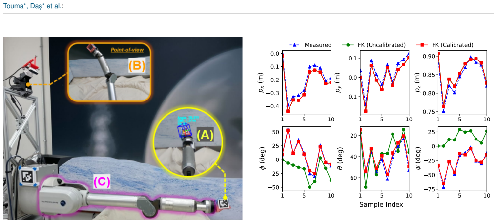
- [X-B, VIII-B] The reported 'Accuracy = 100% × 0.52/0.57 ≈ 91.2%' is not a well-defined accuracy metric. It appears to compare the final estimated correction (0.52 rad) with the QP-solved offset (0.57 rad), both outputs of the same estimation pipeline, rather than measuring the physical effect on the end-effector. The validation in Fig. 13 also uses the same mast-camera/AprilTag pipeline for the 'measured' poses and for the recalibration observations, so a systematic AprilTag pose bias would be absorbed into the calibrated DH parameters, and the calibrated curves would agree with the biased vision system without improving true positioning accuracy. The stress-test concern about shared vision ground truth therefore lands: the paper's own text concedes that 'minor discrepancies arise from the marker-based pose-estimation process,' but it provides no error analysis. To support the claim that the arm is restored to operational status, the authors should report pre- and post-calibration end-effector translation and orientation errors against an independent reference (e.g., a laser tracker, a calibrated fixture, or a physical touch-off), and they should provide per-trial statistics rather than the single ratio in X-B or the unexplained 90-98% range in X-C.
- [VIII-B, X-B] The central assumption that 'forward kinematics errors can be completely captured by time-invariant DH parameter errors' is only exercised by injecting exactly a constant joint-angle offset in joint 7, which belongs to that assumed model class. This does not support the broader recovery claims in Sections I and III concerning bent links, joint freeze-ups, mechanical degradation, or improper tool loading. Either add a fault experiment outside the assumed model class (e.g., a link-length error, a twist error, or a non-geometric deformation) or explicitly scope the demonstrated recovery claim to constant joint-offset faults. Without such a test, the paper overstates the generality of the recalibration demonstration.
- [V-E, X-C] The LLM-based site selection is presented as a core demonstration of pre-trained, non-hard-coded autonomy, but no ground-truth validation is provided. The paper does not compare the LLM's rankings against independent geological assessment, does not quantify how often the selected site was the genuinely best candidate, and uses uncalibrated integer confidence scores from 1 to 10. The statement in X-C that repeated semantic reasoning tests 'qualitatively reproduced consistent and accurate target selection behavior' is anecdotal without per-trial data or a defined accuracy metric. To support the site-selection claim, the authors should add an evaluation with independent labels or expert human rankings, or they should weaken the conclusion that the system selects 'scientifically optimal' sites.
minor comments (6)
- [X-B] The equation 'Accuracy = 100% × 0.52/0.57 ≈ 91.2%' should be explained in the text: the reader needs to know what the numerator 0.52 and the denominator 0.57 represent, and why their ratio is called an accuracy rather than, say, an offset-recovery fraction.
- [III-F, IX-B] The hardware specification is inconsistent between sections: Section III-F states an 8-core CPU with 8GB RAM, while Section IX-B states an Intel NUC with 64GB RAM and notes that 8GB was sufficient. Please reconcile the two descriptions or clarify which configuration was used for the reported runs.
- [Fig. 13] The Euler-angle subplots in Fig. 13 lack clear axis labels and units; the caption says degrees, but the tick labels alone are not self-explanatory. The Sample Index axis should also be labeled consistently with the position subplots.
- [VIII-C] The QP in Eq. (8) requires rank(Jn) = 4nj, but the paper does not report the Jacobian rank or any observability analysis for the 38-pose calibration run; please provide evidence that the rank condition is satisfied for the joint configuration used.
- [I, X-C] The abstract's phrase 'unlike all prior space missions' is overbroad in light of the cited prior autonomous systems in Section II (OSIRIS-REx, Perseverance, MMX rover); please soften or qualify this claim.
- [X-C] The force-torque penetration depths are listed as '[0.067 0 0 0 .0014 0 0 .0017 0]' without units or a clear mapping to the seven candidate sites; please add units and explain how zero values correspond to 'virtually no penetration.'
Circularity Check
The reported 91.2% recalibration 'accuracy' is computed from the calibration pipeline's own outputs rather than from independent ground truth; the rest of the system's derivation is self-contained.
-
fitted input called prediction
[Section X-B, 'Recalibration Procedure' (paragraph with the 91.2% figure; also Fig. 13 caption)]
"The final computed joint offset correction was determined to be: Accuracy = 100% × 0.52/0.57 ≈ 91.2%. This correction achieved an accuracy improvement of 91.2%, effectively restoring the arm to operational status."
The paper states that a 0.5235 rad fault was injected into joint 7, which is the known ground truth. The 'accuracy' instead divides two quantities produced by the recalibration algorithm itself: the 0.52 rad correction and the 0.57 rad offset determined by the QP solver (Fig. 13 caption). Both numbers come from the same AprilTag/camera pose-estimation and QP fitting chain, and no independent reference (laser tracker, touch-off, or the known injected value) is used. The ratio therefore measures internal consistency of the estimator, not physical positioning accuracy, so the quantitative '91.2%' claim reduces to the method's own outputs rather than to an external check. The later successful scoop delivery is the real independent evidence, which is why the circularity is only partial.
full rationale
The central autonomy framework and the calibration algorithm are not circular by construction: Section VIII re-derives the GP/QP kinematic calibration with explicit equations (Eqs. 1-8), so the method does not rest solely on the self-citations [26], [31], [32]. Test 2 is an end-to-end physical demonstration with force-torque probing and sample delivery, providing independent support for the integrated system. The LLM-based site selection is unvalidated against ground truth, but that is a missing-validation issue, not a circular one. The one concrete circularity is the Test 1 accuracy figure: injected bias 0.5235 rad is known, yet the reported 91.2% compares the algorithm's 0.52 rad correction to the algorithm's 0.57 rad fitted offset, with both taken from the same vision pipeline; the paper's Fig. 13 validation also uses 'measured data' from the same marker-based pose-estimation process, so systematic camera bias would be absorbed into the calibrated DH parameters and would not show up in the reported alignment. Because a successful physical scoop after recalibration independently demonstrates recovery, the score is 4 rather than 6+: the central claim has independent content, but the headline quantitative accuracy claim reduces to the calibration pipeline's own inputs.
Assumptions & free parameters
free parameters (6)
- GP kernel hyperparameters (beta, sigma_f, sigma_n, sigma_s)
- GP-UCB exploration parameter beta_k and weights alpha1, alpha2
- MONSID detection tolerances
- ISI filtering thresholds (size, proximity, reachability)
- LLM confidence scores (1-10) =
8 for high-priority site
- Joint offset correction and QP offset =
0.52 rad and 0.57 rad
assumptions (5)
- domain assumption Forward kinematics errors are completely captured by time-invariant DH parameter errors.
- domain assumption AprilTag fiducial measurements provide accurate ground truth for end-effector pose.
- domain assumption OWLAT simulants (WF-34 quartz sand, MPACS) approximate Europa/Enceladus surface materials and behavior.
- domain assumption GPT-4o's pre-trained knowledge is sufficient for scientific site selection and material inference.
- ad hoc to paper The injected 0.5235 rad encoder bias is representative of realistic faults.
Cite this review
Pith. "Pith review of AI Space Cortex: An Experimental System for Future Era Space Exploration." pith.science (2026). https://pith.science/paper/BZB6RB2T
@misc{pith2026250706574,
  author       = {Pith},
  title        = {Pith review of: AI Space Cortex: An Experimental System for Future Era Space Exploration},
  year         = {2026},
  howpublished = {\url{https://pith.science/paper/BZB6RB2T}},
  note         = {Machine review of arXiv:2507.06574}
}
read the original abstract
Our Robust, Explainable Autonomy for Scientific Icy Moon Operations (REASIMO) effort contributes to NASA's Concepts for Ocean worlds Life Detection Technology (COLDTech) program, which explores science platform technologies for ocean worlds such as Europa and Enceladus. Ocean world missions pose significant operational challenges. These include long communication lags, limited power, and lifetime limitations caused by radiation damage and hostile conditions. Given these operational limitations, onboard autonomy will be vital for future Ocean world missions. Besides the management of nominal lander operations, onboard autonomy must react appropriately in the event of anomalies. Traditional spacecraft rely on a transition into 'safe-mode' in which non-essential components and subsystems are powered off to preserve safety and maintain communication with Earth. For a severely time-limited Ocean world mission, resolutions to these anomalies that can be executed without Earth-in-the-loop communication and associated delays are paramount for completion of the mission objectives and science goals. To address these challenges, the REASIMO effort aims to demonstrate a robust level of AI-assisted autonomy for such missions, including the ability to detect and recover from anomalies, and to perform missions based on pre-trained behaviors rather than hard-coded, predetermined logic like all prior space missions. We developed an AI-assisted, personality-driven, intelligent framework for control of an Ocean world mission by combining a mix of advanced technologies. To demonstrate the capabilities of the framework, we perform tests of autonomous sampling operations on a lander-manipulator testbed at the NASA Jet Propulsion Laboratory, approximating possible surface conditions such a mission might encounter.
Figures


Figures from the paper (10 more)



Reference graph
Works this paper leans on
-
[26]
Bayesian optimal experimental design for robot kinematic calibration,
E. Da¸ s, T. Touma, and J. W. Burdick, “Bayesian optimal experimental design for robot kinematic calibration,” in 2025 IEEE International Conference on Robotics and Automation (ICRA) . IEEE, 2025
work page 2025
-
[31]
An active learning based robot kinematic calibration framework using Gaussian processes,
E. Da¸ s and J. W. Burdick, “An active learning based robot kinematic calibration framework using Gaussian processes,” in 2023 IEEE In- ternational Conference on Robotics and Automation (ICRA) . IEEE, 2023, pp. 11 495–11 501
work page 2023
-
[32]
Towards robust, resilient Ocean world science sampling systems,
T. Touma, E. Da¸ s, J. W. Burdick, E. B. Clark, R. Mackey, M. S. Feather, L. M. Fesq, K. O. Kolcio, and M. Prather, “Towards robust, resilient Ocean world science sampling systems,” in 2023 IEEE Aerospace Conference. IEEE, 2023, pp. 1–9
work page 2023
-
[1]
The NASA roadmap to Ocean worlds,
A. R. Hendrix, T. A. Hurford, L. M. Barge, M. T. Bland, J. S. Bowman, W. Brinckerhoff, B. J. Buratti, M. L. Cable, J. Castillo-Rogez, G. C. Collins et al., “The NASA roadmap to Ocean worlds,” Astrobiology, vol. 19, no. 1, pp. 1–27, 2019
work page 2019
-
[2]
Science overview of the Europa Clipper mission,
R. T. Pappalardo, B. J. Buratti, H. Korth, D. A. Senske, D. L. Blaney, D. D. Blankenship, J. L. Burch, P. R. Christensen, S. Kempf, M. G. Kivelson et al. , “Science overview of the Europa Clipper mission,” Space Science Reviews , vol. 220, no. 4, pp. 1–58, 2024
work page 2024
-
[3]
Exploring the interior of Europa with the Europa Clipper,
J. H. Roberts, W. B. McKinnon, C. M. Elder, G. Tobie, J. B. Biersteker, D. Young, R. S. Park, G. Steinbrügge, F. Nimmo, S. M. Howell et al., “Exploring the interior of Europa with the Europa Clipper,” Space Science Reviews, vol. 219, no. 6, p. 46, 2023
work page 2023
-
[4]
Science goals and mission architecture of the Europa lander mission concept,
K. P. Hand, C. B. Phillips, A. Murray, J. Garvin, E. Maize, R. Gibbs, G. Reeves, A. San Martin, G. Tan-Wang, J. Krajewski et al., “Science goals and mission architecture of the Europa lander mission concept,” The Planetary Science Journal , vol. 3, no. 1, p. 22, 2022
work page 2022
-
[5]
Autonomy for space robots: Past, present, and future,
I. A. Nesnas, L. M. Fesq, and R. A. V olpe, “Autonomy for space robots: Past, present, and future,” Current Robotics Reports , vol. 2, no. 3, pp. 251–263, 2021
work page 2021
Show all 40 references
-
[6]
Demonstrating autonomy for complex space missions: A Europa lander mission au- tonomy prototype,
C. Wagner, C. Mauceri, P. Twu, Y . Marchetti, J. Russino, D. Aguilar, G. Rabideau, S. Tepsuporn, S. Chien, and G. Reeves, “Demonstrating autonomy for complex space missions: A Europa lander mission au- tonomy prototype,” Journal of Aerospace Information Systems, vol. 21, no. 1...
2024
-
[7]
Resiliency in space autonomy: a review,
A. Banerjee, M. Mukherjee, S. Satpute, and G. Nikolakopoulos, “Resiliency in space autonomy: a review,” Current Robotics Reports , vol. 4, no. 1, pp. 1–12, 2023
2023
-
[8]
Model-based fault detection and isolation system for increased autonomy,
K. O. Kolcio, “Model-based fault detection and isolation system for increased autonomy,” in AIAA SPACE 2016, 2016, p. 5225
2016
-
[9]
OWLAT: The evolution of an advanced lander-manipulator testbed for enabling autonomy development for Ocean worlds missions,
E. Tevere, A. Goel, A. Boettcher, E. Kramer, A. Daca, H. Nayar, M. Morley, M. Goldstein, and I. Nesnas, “OWLAT: The evolution of an advanced lander-manipulator testbed for enabling autonomy development for Ocean worlds missions,” in AIAA AVIATION FORUM AND ASCEND 2024 , 2024, p. 4916
2024
-
[10]
OSIRIS-REx: sample return from asteroid (101955) Bennu,
D. Lauretta, S. Balram-Knutson, E. Beshore, W. Boynton, C. Drouet d’Aubigny, D. DellaGiustina, H. Enos, D. Golish, C. Her- genrother, E. Howell et al., “OSIRIS-REx: sample return from asteroid (101955) Bennu,” Space Science Reviews, vol. 212, pp. 925–984, 2017
2017
-
[11]
Autonomous robotics is driving Perseverance rover’s progress on Mars,
V . Verma, M. W. Maimone, D. M. Gaines, R. Francis, T. A. Estlin, S. R. Kuhn, G. R. Rabideau, S. A. Chien, M. M. McHenry, E. J. Graser et al., “Autonomous robotics is driving Perseverance rover’s progress on Mars,” Science Robotics, vol. 8, no. 80, p. eadi3099, 2023
2023
-
[12]
Autonomous surface sampling for the Europa Lander mission concept,
J. Bowkett, S. Chien, Y . Marchetti, J. Nash, D. Moreno, C. Basich, M. Gildner, D. Kim, J. Russino, D. Wang et al., “Autonomous surface sampling for the Europa Lander mission concept,” Science Robotics , vol. 10, no. 102, p. eadi5582, 2025
2025
-
[13]
VLM4Bio: A benchmark dataset to evaluate pretrained vision- language models for trait discovery from biological images,
M. Maruf, A. Daw, K. S. Mehrab, H. B. Manogaran, A. Neog, M. Sawhney, M. Khurana, J. Balhoff, Y . Bakis, B. Altintas et al. , “VLM4Bio: A benchmark dataset to evaluate pretrained vision- language models for trait discovery from biological images,” Advances in Neural Informatio...
2024
-
[14]
GEOBench-VLM: Benchmarking vision-language models for geospatial tasks,
M. S. Danish, M. A. Munir, S. R. A. Shah, K. Kuckreja, F. S. Khan, P. Fraccaro, A. Lacoste, and S. Khan, “GEOBench-VLM: Benchmarking vision-language models for geospatial tasks,” arXiv preprint arXiv:2411.19325, 2024
2024 arXiv
-
[15]
Good at captioning bad at counting: Bench- marking GPT-4V on Earth observation data,
C. Zhang and S. Wang, “Good at captioning bad at counting: Bench- marking GPT-4V on Earth observation data,” in Proceedings of the IEEE/CVF Conference on Computer Vision and Pattern Recognition , 2024, pp. 7839–7849
2024
-
[16]
Adapt- ing a foundation model for space-based tasks,
M. Foutter, P. Bhoj, R. Sinha, A. Elhafsi, S. Banerjee, C. Agia, J. Kruger, T. Guffanti, D. Gammelli, S. D’Amico et al. , “Adapt- ing a foundation model for space-based tasks,” arXiv preprint arXiv:2408.05924, 2024
2024 arXiv
-
[17]
Survey on fault detection, isolation, and recovery strategies in the space domain,
M. Tipaldi and B. Bruenjes, “Survey on fault detection, isolation, and recovery strategies in the space domain,” Journal of Aerospace Information Systems, vol. 12, no. 2, pp. 235–256, 2015
2015
-
[18]
Fault detection, isolation and recovery in the MMX rover locomotion subsystem,
J. Skibbe, E. Aitier, S. Barthelmes, M. Bihler, G. Brusq, F. Hacker, and H.-J. Sedlmayr, “Fault detection, isolation and recovery in the MMX rover locomotion subsystem,” in 2023 IEEE Aerospace Conference . IEEE, 2023, pp. 1–9
2023
-
[19]
Online tree- based planning for active spacecraft fault estimation and collision avoidance,
J. Ragan, B. Riviere, F. Y . Hadaegh, and S.-J. Chung, “Online tree- based planning for active spacecraft fault estimation and collision avoidance,” Science Robotics, vol. 9, no. 93, p. eadn4722, 2024
2024
-
[20]
The calibration index and taxonomy for robot kinematic calibration methods,
J. M. Hollerbach and C. W. Wampler, “The calibration index and taxonomy for robot kinematic calibration methods,” The international journal of robotics research , vol. 15, no. 6, pp. 573–591, 1996
1996
-
[21]
Kalibrot: A simple-to-use MATLAB package for robot kinematic calibration,
F. Cursi, W. Bai, and P. Kormushev, “Kalibrot: A simple-to-use MATLAB package for robot kinematic calibration,” in 2021 IEEE/RSJ International Conference on Intelligent Robots and Systems (IROS) . IEEE, 2021, pp. 8852–8859
2021
-
[22]
Comparison of the efficiency of five observability indices for robot calibration,
A. Joubair and I. A. Bonev, “Comparison of the efficiency of five observability indices for robot calibration,” Mechanism and Machine Theory, vol. 70, pp. 254–265, 2013
2013
-
[23]
Active robot calibration algorithm,
Y . Sun and J. M. Hollerbach, “Active robot calibration algorithm,” in 2008 IEEE international conference on robotics and automation . IEEE, 2008, pp. 1276–1281
2008
-
[24]
Optimal experiment design for elasto- geometrical calibration of industrial robots,
K. Kamali and I. A. Bonev, “Optimal experiment design for elasto- geometrical calibration of industrial robots,” IEEE/ASME Transactions on Mechatronics, vol. 24, no. 6, pp. 2733–2744, 2019
2019
-
[25]
Geometric calibration of industrial robots using enhanced partial pose measure- ments and design of experiments,
Y . Wu, A. Klimchik, S. Caro, B. Furet, and A. Pashkevich, “Geometric calibration of industrial robots using enhanced partial pose measure- ments and design of experiments,” Robotics and Computer-Integrated Manufacturing, vol. 35, pp. 151–168, 2015
2015
-
[27]
Segment anything,
A. Kirillov, E. Mintun, N. Ravi, H. Mao, C. Rolland, L. Gustafson, T. Xiao, S. Whitehead, A. C. Berg, W.-Y . Lo et al. , “Segment anything,” in Proceedings of the IEEE/CVF international conference on computer vision , 2023, pp. 4015–4026. VOLUME , 25 T ouma*, Da¸ s* et al.:
2023
-
[28]
GPT-4 technical report,
J. Achiam, S. Adler, S. Agarwal, L. Ahmad, I. Akkaya, F. L. Aleman, D. Almeida, J. Altenschmidt, S. Altman, S. Anadkat et al. , “GPT-4 technical report,” arXiv preprint arXiv:2303.08774 , 2023
2023 arXiv
-
[29]
The Ingenuity Helicopter on the perseverance rover,
J. Balaram, M. Aung, and M. P. Golombek, “The Ingenuity Helicopter on the perseverance rover,” Space Science Reviews , vol. 217, no. 4, p. 56, 2021
2021
-
[30]
Model-based approach to rover health assessment for increased productivity,
K. Kolcio, L. Fesq, and R. Mackey, “Model-based approach to rover health assessment for increased productivity,” in 2017 IEEE Aerospace Conference. IEEE, 2017, pp. 1–13
2017
-
[33]
R. M. Murray, Z. Li, and S. S. Sastry, A mathematical introduction to robotic manipulation. CRC press, 2017
2017
-
[34]
C. R. Rasmussen and C. K. Williams, Gaussian processes for machine learning. The MIT Press, 2006
2006
-
[35]
Matérn Gaussian processes on Riemannian manifolds,
V . Borovitskiy, A. Terenin, P. Mostowsky, and M. Deisenroth, “Matérn Gaussian processes on Riemannian manifolds,” in Advances in Neural Information Processing Systems , vol. 33, 2020, pp. 12 426–12 437
2020
-
[36]
Gaussian process optimization in the bandit setting: No regret and experimental design,
N. Srinivas, A. Krause, S. M. Kakade, and M. Seeger, “Gaussian process optimization in the bandit setting: No regret and experimental design,” arXiv preprint arXiv:0912.3995 , 2009
2009 arXiv
-
[37]
Visual end- effector position error compensation for planetary robotics,
M. Bajracharya, M. DiCicco, P. Backes, and K. Nickels, “Visual end- effector position error compensation for planetary robotics,” Journal of Field Robotics , vol. 24, no. 5, pp. 399–420, 2007
2007
-
[38]
DARTS-multibody modeling, simulation and analysis soft- ware,
A. Jain, “DARTS-multibody modeling, simulation and analysis soft- ware,” in Multibody Dynamics 2019: Proceedings of the 9th ECCO- MAS Thematic Conference on Multibody Dynamics . Springer, 2020, pp. 433–441
2019
-
[39]
Flexible layouts for fidu- cial tags,
M. Krogius, A. Haggenmiller, and E. Olson, “Flexible layouts for fidu- cial tags,” in 2019 IEEE/RSJ International Conference on Intelligent Robots and Systems (IROS) , 2019, pp. 1898–1903
2019
-
[40]
EELS: Autonomous snake-like robot with task and motion planning capabilities for ice world exploration,
T. S. Vaquero, G. Daddi, R. Thakker, M. Paton, A. Jasour, and et al., “EELS: Autonomous snake-like robot with task and motion planning capabilities for ice world exploration,” Science Robotics, vol. 9, no. 88, p. eadh8332, 2024. 26 VOLUME ,
2024
Reviewed August 6, 2026 · model on record in the stance chip above.
Discussion (0). Sign in to comment.