REVIEW 2 major objections 3 minor 2 cited by
Resonant two-qubit gates for fermionic simulations with spin qubits
T0 review · 2 major / 3 minor · reviewed 2026-08-06 · deepseek-v4-flash
Pith's one-line read A single exchange pulse superposing baseband and resonant drives implements the full fSim gate family in spin qubits; the authors validate it with an iSWAP at 93.8(5)% fidelity.
desk verdict Solid demonstration of a resonant fSim-type gate in germanium hole spins, with a genuinely useful calibration protocol; the 93.8% fidelity should be treated as provisional because the IRB reference group is not a two-qubit 2-design. read the letter →
The pith
A machine-rendered reading of the paper's core claim, the machinery that carries it, and where it could break.
The reading
What carries the argument
The central object is the fSim gate $fSim(\gamma,\zeta) = iSWAP^{-2\gamma/\pi} CZ^{\zeta/\pi}$, built from a single voltage pulse on the inter-dot barrier: a smooth-edged Tukey-windowed baseband excursion with a superimposed ac drive at the swap resonance $f_{SWAP} = \sqrt{\Delta E_z^2 + J^2}/h$. The ac part drives coherent $|\uparrow\downarrow\rangle \leftrightarrow |\downarrow\uparrow\rangle$ oscillations that set $\gamma$, while the time-integrated exchange $\zeta = \int J_{dc}(t)\,dt/\hbar + \bar{J}_{ac}t_{ac}/\hbar$ accumulates the conditional phase. The load-bearing mechanism is the drive phase, which absorbs ramp-induced and residual phases so they can be corrected with virtual Z rotations; this is what removes the need for a separate CZ calibration pulse and keeps the gate short.
What would settle it
Repeat the interleaved benchmarking of the same calibrated diabatic iSWAP gate using a full two-qubit Clifford reference group instead of the single-qubit-Clifford set described in App. F.2; if the extracted fidelity moves outside 93.8(5)% by more than the stated uncertainty, the reported fidelity is not a rigorous estimate of the gate.
Extended reading notes
Core claim
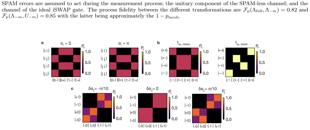
The central claim is that simultaneous resonant and baseband exchange pulses on a single barrier gate produce the fSim interaction in one pulse, with the swap parameter set by the resonant drive duration and amplitude ($\gamma = j_{12}t_{ac}/4\hbar$) and the conditional phase set by the time-integrated exchange from both dc and ac components. After virtual-Z corrections of the single-qubit phases and a drive-phase update, the realized unitary is $fSim(\gamma,\zeta) = iSWAP^{-2\gamma/\pi} CZ^{\zeta/\pi}$. On a germanium double quantum dot holding two hole spins, the authors calibrate the iSWAP point $fSim(-\pi/2,2\pi)$ and measure 93.8(5)% fidelity for the diabatic gate (5 ns ramp, 343 ns total) and 88.9(7)% for the adiabatic gate (100 ns ramp, 485 ns total) using interleaved randomized benchmarking. Quantum process tomography of the diabatic gate gives a gate fidelity of 86.3% after removing state-preparation-and-measurement errors, identifies qubit decoherence as the dominant error source, and places calibration errors at roughly the level of the ~3% single-qubit gate error floor.
Load-bearing premise
The 93.8(5)% fidelity rests on the assumption that a reference set of only single-qubit Clifford gates randomizes the iSWAP error channel well enough for the standard interleaved-benchmarking formula to give an unbiased fidelity estimate.
Editorial extensions
If this is right
- Spin qubits gain a native, tunable fSim gate without pulsing the exchange far above the Zeeman difference, avoiding the charge-noise penalty of baseband SWAP approaches.
- The iSWAP point is reached with a single calibrated pulse: 93.8(5)% fidelity with a fast 5 ns ramp and 88.9(7)% with a 100 ns ramp, the shorter gate performing better because dephasing is the dominant error.
- The off-resonant Ramsey calibration route generalizes to arbitrary fSim($\gamma,\zeta$) parameters, so the same pulse scheme can be tuned to other points of the gate family rather than only iSWAP.
- Because the drive phase can be updated when virtual Z gates are applied, the gate is compatible with virtual Z rotations and with pulse-shaping and synchronization methods for further error reduction.
- Process tomography indicates that decoherence, not calibration, limits current performance; longer coherence times and larger Zeeman differences should directly improve fidelity.
Reading between the lines
- A benchmark using the full two-qubit Clifford group rather than the single-qubit-Clifford reference set of App. F.2 would test whether the 93.8(5)% number is unbiased; if the extracted fidelity shifts beyond the quoted uncertainty, the reported value is a conditional estimate, not a rigorous gate fidelity.
- The same drive-phase freedom should make continuous Givens rotations available to spin qubits by sweeping $\gamma$ instead of stopping at the iSWAP point; the paper notes compatibility with this direction but does not demonstrate the rotations.
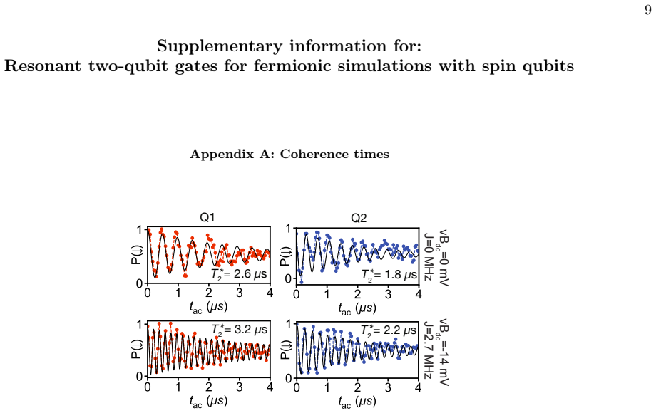
- A quantitative dephasing model using the measured coherence times (1.8 and 2.6 $\mu$s) and gate durations (343 and 485 ns) would yield a predicted error floor; comparing it with the measured 93.8% would show how much headroom the pulse scheme still has.
Editorial analysis
A structured set of objections, weighed in public.
Referee Report
Summary. The paper reports a method for realizing tunable fermionic simulation (fSim) two-qubit gates in semiconductor spin qubits by applying a single barrier pulse that combines a baseband exchange pulse with a resonant exchange drive. The authors derive the resulting unitary in the rotating-wave approximation, calibrate the swap angle γ and conditional phase ζ using Ramsey sequences and partial tomography, and demonstrate a resonant iSWAP gate between two hole spins in germanium. The headline result is a 93.8(5)% fidelity extracted from interleaved randomized benchmarking, with quantum process tomography used to attribute the remaining error mainly to decoherence. The manuscript also provides a detailed theoretical appendix covering the unitary evolution, single-qubit phase corrections, and tomographic analysis.
Significance. If the central claims hold, this is a useful contribution: it provides a way to implement the full fSim(γ,ζ) family natively in spin qubits with a single pulse, avoiding the large exchange values used in diabatic SWAP gates and remaining compatible with virtual Z rotations. The paper's strengths include the explicit analytic derivation of the gate unitary in Appendix C, the independent support from swap chevrons, conditional Ramsey measurements, and partial tomography, and the transparent discussion of SPAM handling in the QPT analysis. However, the headline fidelity claim is load-bearing and rests on a benchmarking protocol whose validity for two-qubit gates is not established.
major comments (2)
- [Sec. V and App. F.2] The interleaved randomized benchmarking fidelity of 93.8(5)% is not a rigorous estimate of the iSWAP gate fidelity. The reference group used in App. F.2 is the set of two-qubit Clifford gates composed only of single-qubit gates, i.e., the local Clifford group C1 × C1. This group is a 2-design on each qubit separately, but it is not a unitary 2-design on the two-qubit Hilbert space, and it does not twirl two-qubit-correlated error channels, including the error channel of the interleaved iSWAP gate, into a global depolarizing channel. The formula F = 1 − (d−1)/d (1 − α_interleaved/α_reference) cited from Ref. [40] is derived under the full-Clifford twirl assumption. Consequently, α_reference and α_interleaved need not be single depolarizing parameters, and their ratio is not guaranteed to equal the average gate fidelity. The authors should either benchmark with a full two-qubit Clifford reference group or clearly restrict the claim to a protocol-dependent estimate and temper the abstract accordingly.
- [Sec. V and Fig. 4] The SPAM-corrected quantum process tomography fidelity for the same diabatic iSWAP gate is 86.3%, about 7.5 percentage points below the interleaved RB value. The manuscript attributes this discrepancy to SPAM assumptions and neglected single-qubit errors, but that explanation is not quantitatively anchored: the quoted SPAM-corrected QPT number is stated without a detailed derivation in the main text, and the reader cannot see how the SPAM channel model converts the raw tomography into this value. This gap is consistent with an upward bias in the local-Clifford IRB estimate, so the discrepancy should be analyzed explicitly, for example by applying the same SPAM correction to a full-Clifford RB run or by reporting both numbers with a clear statement of which one is claimed to be the gate fidelity.
minor comments (3)
- [Sec. IV] The sentence 'calibration errors arising form the diabatic activation of J' should read 'arising from the diabatic activation of J'.
- [Sec. V and App. E, Table I] The SPAM-corrected QPT fidelity for the diabatic gate is quoted as 86.3% in the main text, but Table I reports values up to 89.5% (standard method, Λ−p) and 86.0% (ML method, Λ−m). The definition of the number quoted in the text should be reconciled with the table entries.
- [App. F.2] The description of the interleaved RB recovery gate is somewhat terse: it states that the recovery gate 'may include multiple iSWAP gates' after transpilation, but the number of interleaved iSWAP gates per sequence and its effect on the decay curve offset are not quantified. A sentence explaining how the alpha extraction accounts for this offset would improve reproducibility.
Circularity Check
No circularity found: the fSim derivation is self-contained (App. C), the iSWAP fidelity is an experimental benchmark rather than a fitted input, and the IRB/QPT concerns are validity limitations, not circular reductions.
full rationale
The central derivation chain is not circular. Appendix C derives the fSim unitary from the time-dependent exchange Hamiltonian in the rotating-wave approximation, giving gamma = j12*tac/(4hbar) in Eq. (C22) and zeta = ∫Jdc(hbar^-1)dt + Jbar_ac*hbar^-1*tac in Eq. (C23). These relations are not assumed from the target iSWAP gate; they are parameterizations of the physical evolution. The subsequent calibration independently sets gamma via resonant swap chevrons and zeta via off-resonant Ramsey exchange extraction and partial tomography, and the fSim unitary is then checked with process tomography and randomized benchmarking. The headline 93.8(5)% iSWAP fidelity is a measured outcome of interleaved RB, not a quantity made equal to an input by construction. The skeptical concern that App. F.2 uses a two-qubit Clifford group composed only of single-qubit gates as the IRB reference group is a legitimate statistical-validity issue: the local Clifford group is not a unitary 2-design on the four-dimensional Hilbert space, so the depolarizing-noise formula cited from Ref. [40] may not rigorously apply. But this is not circularity; the fidelity estimate is not derived from the calibration parameters by definition. Similarly, the SPAM correction in App. E assumes a commuting SPAM channel structure that the authors explicitly acknowledge is not generally valid, and the QPT fidelity (86.3%) differs from the RB value; this is an acknowledged limitation of the tomographic model, not a self-referential reduction. No load-bearing argument rests on a self-citation: the cited prior work [32] is used for device details, and the theory of resonant exchange driving is standard or externally supported. Therefore no circular step is exhibited, and the paper's core claim stands as an experimental demonstration with independent calibration and characterization.
Assumptions & free parameters
free parameters (5)
- J̄ac, average exchange induced by the ac drive =
calibrated per gate, e.g. at vBac=5.3 mV
- j12, exchange Rabi coupling =
set by vBac=4.3 mV (diabatic) or 5.3 mV (adiabatic)
- Δ1, Δ2, qubit frequency shifts during the pulse =
6.23 MHz and -1.69 MHz (diabatic, Table III)
- tdc, tac, pulse durations =
333/290 ns (diabatic), 285/253 ns (adiabatic)
- θ1, θ2, single-qubit phase corrections =
0.90 rad and 2.68 rad mod 2π (adiabatic, Table III)
assumptions (5)
- domain assumption Time-dependent Hamiltonian H_I/H_II of Eq. (C3)/(C11): exchange term (J/4)Σ σi⊗σi plus independent qubit frequency shifts Δ1, Δ2.
- domain assumption Rotating-wave approximation in interval II, leading to Eq. (C12).
- domain assumption Adiabatic treatment of the ramps in intervals I and III, or neglect of diabatic calibration errors for tramp=5 ns.
- domain assumption SPAM channel commutes with single-qubit Clifford gates and can be represented as a single CPTP channel, Eq. (E12).
- domain assumption The reference RB sequence built only from single-qubit Clifford gates provides a valid depolarizing parameter for the IRB formula.
Cite this review
Pith. "Pith review of Resonant two-qubit gates for fermionic simulations with spin qubits." pith.science (2026). https://pith.science/paper/PYLZJFK4
@misc{pith2026250713781,
  author       = {Pith},
  title        = {Pith review of: Resonant two-qubit gates for fermionic simulations with spin qubits},
  year         = {2026},
  howpublished = {\url{https://pith.science/paper/PYLZJFK4}},
  note         = {Machine review of arXiv:2507.13781}
}
read the original abstract
In gate-defined semiconductor spin qubits, the highly tunable Heisenberg exchange interaction is leveraged to implement fermionic two-qubit gates such as CZ and SWAP. However, the broader family of fermionic simulation (fSim) gates remains unexplored, and has the potential to enhance the performance of near-term quantum simulation algorithms. Here, we demonstrate a method to implement the fSim gate set in spin qubits using a single pulse combining baseband and resonant exchange drives. This approach minimizes gate duration and drive amplitude, mitigating decoherence and crosstalk. We validate its effectiveness by realizing a resonant iSWAP gate between two hole spins in germanium, achieving a fidelity of 93.8(5)% extracted with interleaved randomized benchmarking. Quantum process tomography confirms accurate gate calibration and identifies qubit decoherence as the dominant error source. Our results establish a practical route toward a versatile and efficient two-qubit gate set for spin-based quantum processors.
Figures


Figures from the paper (6 more)



Forward citations
Cited by 2 Pith papers
-
Quantum Accreditation with Non-Clifford Two-qubit Gates
Develops practical scalable protocols to upper-bound total variation distance for quantum circuits with non-Clifford two-qubit gates and generalizes Pauli twirling to non-Pauli bases.
-
Spin-orbit-enabled realization of arbitrary two-qubit gates on moving spins
Spin-orbit coupling during shuttling of two spin qubits can realize any two-qubit gate in one step.
Reference graph
Works this paper leans on
-
[40]
Benchmarking gate fidelities in a si/sige two-qubit device,
X. Xue, T. Watson, J. Helsen, D. R. Ward, D. E. Sav- age, M. G. Lagally, S. N. Coppersmith, M. Eriksson, S. Wehner, and L. M. Vandersypen, “Benchmarking gate fidelities in a si/sige two-qubit device,” Physical Review X 9, 021011 (2019)
work page 2019
-
[1]
Quantum simulation of electronic structure with linear depth and connectivity,
I. D. Kivlichan, J. McClean, N. Wiebe, C. Gidney, A. Aspuru-Guzik, G. K. L. Chan, and R. Babbush, “Quantum simulation of electronic structure with linear depth and connectivity,” Physical Review Letters120 (2018)
work page 2018
-
[2]
Strategies for solving the Fermi-Hubbard model on near- term quantum computers,
C. Cade, L. Mineh, A. Montanaro, and S. Stanisic, “Strategies for solving the Fermi-Hubbard model on near- term quantum computers,” Phys. Rev. B102, 235122 (2020)
work page 2020
-
[3]
Quantum circuits for strongly correlated quantum systems,
F. Verstraete, J. I. Cirac, and J. I. Latorre, “Quantum circuits for strongly correlated quantum systems,” Phys. Rev. A79, 032316 (2009)
work page 2009
-
[4]
Concurrent fermionic simu- lation gate,
Z. Jiang and M. H. Ansari, “Concurrent fermionic simu- lation gate,” arXiv preprint arXiv:2411.19398 (2024)
-
[5]
Demonstrating a con- tinuous set of two-qubit gates for near-term quantum algorithms,
B. Foxen, C. Neill, A. Dunsworth, P. Roushan, B. Chiaro, A. Megrant, J. Kelly and others, “Demonstrating a con- tinuous set of two-qubit gates for near-term quantum algorithms,” Phys. Rev. Lett.125, 120504 (2020)
work page 2020
-
[6]
Implementation of xy entangling gates with a single calibrated pulse,
D. M. Abrams, N. Didier, B. R. Johnson, M. P. da Silva, and C. A. Ryan, “Implementation of xy entangling gates with a single calibrated pulse,” Nature Electronics3, 744 (2020)
work page 2020
-
[7]
Realization of high-fidelity CZ and ZZ-free iSWAP gates with a tunable coupler,
Y. Sung, L. Ding, J. Braumüller, A. Vepsäläinen, B. Kan- nan, M. Kjaergaard, A. Greene, G. O. Samach, C. Mc- Nally, D. Kim, A. Melville, B. M. Niedzielski, M. E. Schwartz, J. L. Yoder, T. P. Orlando, S. Gustavsson, and W. D. Oliver, “Realization of high-fidelity CZ and ZZ-free iSWAP gates with a tunable coupler,” Physical Review X 11 (2021)
work page 2021
Show all 74 references
-
[8]
Gate-efficient simulation of molecular eigen- states on a quantum computer,
M. Ganzhorn, D. J. Egger, P. Barkoutsos, P. Ollitrault, G. Salis, N. Moll, M. Roth, A. Fuhrer, P. Mueller, S. Wo- erner, et al., “Gate-efficient simulation of molecular eigen- states on a quantum computer,” Physical Review Applied 11, 044092 (2019)
2019
-
[9]
Hartree-fock on a superconducting qubit quantum computer,
F. Arute, K. Arya, R. Babbush, D. Bacon, J. C. Bardin, R. Barends, S. Boixo, M. Broughton, B. B. Buckley, et al., “Hartree-fock on a superconducting qubit quantum computer,” Science369, 1084 (2020)
2020
-
[10]
One-step implementation of a nonadiabatic geometric fsim gate in superconducting circuits,
M.-R. Yun, Z. Shan, L.-L. Sun, L.-L. Yan, Y. Jia, S.-L. Su, and G. Chen, “One-step implementation of a nonadiabatic geometric fsim gate in superconducting circuits,” Physical Review A110, 022608 (2024)
2024
-
[11]
Observation of separated dynamics of charge and spin in the fermi- hubbard model,
Google AI Quantum and Collaborators, “Observation of separated dynamics of charge and spin in the fermi- hubbard model,” (2020), arXiv:2010.07965
2020 arXiv
-
[12]
Proposalforentanglinggatesonfluxonium qubits via a two-photon transition,
K. N. Nesterov, Q. Ficheux, V. E. Manucharyan, and M.G.Vavilov,“Proposalforentanglinggatesonfluxonium qubits via a two-photon transition,” PRX Quantum2, 020345 (2021)
2021
-
[13]
High fidelity two-qubit gates on fluxoniums using a tun- able coupler,
I. N. Moskalenko, I. A. Simakov, N. N. Abramov, A. A. Grigorev, D. O. Moskalev, A. A. Pishchimova, N. S. Smirnov, E. V. Zikiy, I. A. Rodionov, and I. S. Besedin, “High fidelity two-qubit gates on fluxoniums using a tun- able coupler,” npj Quantum Information8, 130 (2022)
2022
-
[14]
A programmable two-qubit quantum processor in silicon,
T. Watson, S. Philips, E. Kawakami, D. Ward, P. Scarlino, M. Veldhorst, D. Savage, M. Lagally, M. Friesen, S. Cop- persmith, et al., “A programmable two-qubit quantum processor in silicon,” Nature555, 633 (2018)
2018
-
[15]
A four-qubit germanium quantum processor,
N. W. Hendrickx, W. I. Lawrie, M. Russ, F. van Riggelen, S. L. de Snoo, R. N. Schouten, A. Sammak, G. Scappucci, and M. Veldhorst, “A four-qubit germanium quantum processor,” Nature 591, 580 (2021)
2021
-
[16]
Quantum logic with spin qubits crossing the surface code threshold,
X. Xue, M. Russ, N. Samkharadze, B. Undseth, A. Sam- mak, G. Scappucci, and L. M. Vandersypen, “Quantum logic with spin qubits crossing the surface code threshold,” Nature 601, 343 (2022). 7
2022
-
[17]
Operating semiconductor quantum processors with hopping spins,
C.-A. Wang, V. John, H. Tidjani, C. X. Yu, A. S. Ivlev, C. Déprez, F. van Riggelen-Doelman, B. D. Woods, N. W. Hendrickx, W. I. Lawrie,et al., “Operating semiconductor quantum processors with hopping spins,” Science385, 447 (2024)
2024
-
[18]
A 300 mm foundry silicon spin qubit unit cell exceeding 99% fidelity in all opera- tions,
P. Steinacker, N. D. Stuyck, W. H. Lim, T. Tanttu, M. Feng, A. Nickl, S. Serrano, M. Candido, J. D. Ci- fuentes, F. E. Hudson,et al., “A 300 mm foundry silicon spin qubit unit cell exceeding 99% fidelity in all opera- tions,” arXiv:2410.15590 (2024)
2024 arXiv
-
[19]
Precision tomography of a three-qubit donor quantum processor in silicon,
M. T. Mądzik, S. Asaad, A. Youssry, B. Joecker, K. M. Rudinger, E. Nielsen, K. C. Young, T. J. Proctor, A. D. Baczewski, A. Laucht,et al., “Precision tomography of a three-qubit donor quantum processor in silicon,” Nature 601, 348 (2022)
2022
-
[20]
Grover’s algorithm in a four-qubit silicon processor above the fault-tolerant threshold,
I. Thorvaldson, D. Poulos, C. Moehle, S. Misha, H. Edl- bauer, J. Reiner, H. Geng, B. Voisin, M. Jones, M. Don- nelly, et al., “Grover’s algorithm in a four-qubit silicon processor above the fault-tolerant threshold,” Nature Nan- otechnology , 1 (2025)
2025
-
[21]
Swap gate for spin qubits based on silicon devices integrated with a micromagnet,
M. Ni, R.-L. Ma, Z.-Z. Kong, X. Xue, S.-K. Zhu, C. Wang, A.-R. Li, N. Chu, W.-Z. Liao, G. Cao,et al., “Swap gate for spin qubits based on silicon devices integrated with a micromagnet,” Nano Letters25, 3766 (2025)
2025
-
[22]
Design and inte- gration of single-qubit rotations and two-qubit gates in silicon above one kelvin,
L. Petit, M. Russ, G.H. Eenink, W. I.Lawrie, J.S. Clarke, L. M. Vandersypen, and M. Veldhorst, “Design and inte- gration of single-qubit rotations and two-qubit gates in silicon above one kelvin,” Communications Materials3, 82 (2022)
2022
-
[23]
Ro- bust two-qubit gates for donors in silicon controlled by hyperfine interactions,
R. Kalra, A. Laucht, C. D. Hill, and A. Morello, “Ro- bust two-qubit gates for donors in silicon controlled by hyperfine interactions,” Phys. Rev. X4, 021044 (2014)
2014
-
[24]
Quantum gates with oscillating exchange interaction,
D. Q. L. Nguyen, I. Heinz, and G. Burkard, “Quantum gates with oscillating exchange interaction,” Quantum Science and Technology9, 15020 (2023)
2023
-
[25]
Simple framework for systematic high- fidelity gate operations,
M. Rimbach-Russ, S. G. J. Philips, X. Xue, and L. M. K. Vandersypen, “Simple framework for systematic high- fidelity gate operations,” Quantum Science and Technol- ogy 8, 45025 (2023)
2023
-
[26]
Coherent transfer of quantum information in a silicon double quantum dot using resonant SWAP gates,
A. J. Sigillito, M. J. Gullans, L. F. Edge, M. Borselli, and J. R. Petta, “Coherent transfer of quantum information in a silicon double quantum dot using resonant SWAP gates,” npj Quantum Inf.5, 110 (2019)
2019
-
[27]
Diverse set of two-qubit gates for spin qubits in semiconduc- tor quantum dots,
M. Ni, R.-L. Ma, Z.-Z. Kong, N. Chu, S.-K. Zhu, C. Wang, A.-R. Li, W.-Z. Liao, G. Cao, G.-L. Wang,et al., “Diverse set of two-qubit gates for spin qubits in semiconduc- tor quantum dots,” Physical Review Applied23, 024065 (2025)
2025
-
[28]
Phase flip code with semiconductor spin qubits,
F. Van Riggelen, W. Lawrie, M. Russ, N. Hendrickx, A. Sammak, M. Rispler, B. Terhal, G. Scappucci, and M. Veldhorst, “Phase flip code with semiconductor spin qubits,” npj Quantum Information8, 124 (2022)
2022
-
[29]
Nonlinear response and crosstalk of electrically driven silicon spin qubits,
B. Undseth, X. Xue, M. Mehmandoost, M. Rimbach- Russ, P. T. Eendebak, N. Samkharadze, A. Sammak, V. V. Dobrovitski, G. Scappucci, and L. M. Vandersypen, “Nonlinear response and crosstalk of electrically driven silicon spin qubits,” Physical Review Applied19, 044078 (2023)
2023
-
[30]
Capac- itive crosstalk in gate-based dispersive sensing of spin qubits,
E. G. Kelly, A. Orekhov, N. W. Hendrickx, M. Mer- genthaler, F. J. Schupp, S. Paredes, R. S. Eggli, A. V. Kuhlmann, P. Harvey-Collard, A. Fuhrer,et al., “Capac- itive crosstalk in gate-based dispersive sensing of spin qubits,” Applied Physics Letters123 (2023)
2023
-
[31]
Compiling arbi- trary single-qubit gates via the phase shifts of microwave pulses,
J. Chen, D. Ding, C. Huang, and Q. Ye, “Compiling arbi- trary single-qubit gates via the phase shifts of microwave pulses,” Phys. Rev. Res.5, L022031 (2023)
2023
-
[32]
A dressed singlet-triplet qubit in germanium,
K. Tsoukalas, U. von Lüpke, A. Orekhov, B. Hetényi, I. Seidler, L. Sommer, E. G. Kelly, L. Massai, M. Aldeghi, M. Pita-Vidal,et al., “A dressed singlet-triplet qubit in germanium,” arXiv preprint arXiv:2501.14627 (2025)
2025
-
[33]
Sweet- spot operation of a germanium hole spin qubit with highly anisotropic noise sensitivity,
N. Hendrickx, L. Massai, M. Mergenthaler, F. Schupp, S. Paredes, S. Bedell, G. Salis, and A. Fuhrer, “Sweet- spot operation of a germanium hole spin qubit with highly anisotropic noise sensitivity,” Nature Materials , 1 (2024)
2024
-
[34]
Prospects of silicide contacts for silicon quantum elec- tronic devices,
K. Tsoukalas, F. Schupp, L. Sommer, I. Bou- quet, M. Mergenthaler, S. Paredes, N. Vico Triv- iño, M. Luisier, G. Salis, P. Harvey-Collard, et al., “Prospects of silicide contacts for silicon quantum elec- tronic devices,” Applied Physics Letters 125 (2024), https://doi.org/10....
2024 doi
-
[35]
High-fidelity single-shot readout for a spin qubit via an enhanced latching mechanism,
P. Harvey-Collard, B. D’Anjou, M. Rudolph, N. T. Ja- cobson, J. Dominguez, G. A. Ten Eyck, J. R. Wendt, T. Pluym, M. P. Lilly, W. A. Coish, M. Pioro-Ladrière, and M. S. Carroll, “High-fidelity single-shot readout for a spin qubit via an enhanced latching mechanism,” Phys. Rev....
2018
-
[36]
Identifying and miti- gating errors in hole spin qubit readout,
E. G. Kelly, L. Massai, B. Hetényi, M. Pita-Vidal, A. Orekhov, C. Carlsson, I. Seidler, K. Tsoukalas, L. Sommer, M. Aldeghi, et al., “Identifying and miti- gating errors in hole spin qubit readout,” arXiv preprint arXiv:2504.06898 (2025)
2025 arXiv
-
[37]
Reduced sensitivity to charge noise in semiconduc- tor spin qubits via symmetric operation,
M. Reed, B. Maune, R. Andrews, M. Borselli, K. Eng, M. Jura, A. Kiselev, T. Ladd, S. Merkel, I. Milosavljevic, et al., “Reduced sensitivity to charge noise in semiconduc- tor spin qubits via symmetric operation,” Physical review letters 116, 110402 (2016)
2016
-
[38]
Resonantly driven singlet-triplet spin qubit in silicon,
K. Takeda, A. Noiri, J. Yoneda, T. Nakajima, and S. Tarucha, “Resonantly driven singlet-triplet spin qubit in silicon,” Physical Review Letters124, 117701 (2020)
2020
-
[39]
Exchange anisotropies in microwave-driven singlet-triplet qubits,
J. Saez-Mollejo, D. Jirovec, Y. Schell, J. Kukucka, S. Cal- caterra, D. Chrastina, G. Isella, M. Rimbach-Russ, S. Bosco, and G. Katsaros, “Exchange anisotropies in microwave-driven singlet-triplet qubits,” Nature Commu- nications 16, 3862 (2025)
2025
-
[41]
Complete char- acterization of a quantum process: The two-bit quantum gate,
J. F. Poyatos, J. I. Cirac, and P. Zoller, “Complete char- acterization of a quantum process: The two-bit quantum gate,” Phys. Rev. Lett.78, 390 (1997)
1997
-
[42]
AnInvitationto Quantum Tomography,
L.M.Artiles, R.D.Gill, andM.I.Gută,“AnInvitationto Quantum Tomography,” Journal of the Royal Statistical Society Series B: Statistical Methodology67, 109 (2004)
2004
-
[43]
Self-consistent quantum process tomography,
S. T. Merkel, J. M. Gambetta, J. A. Smolin, S. Poletto, A. D. Córcoles, B. R. Johnson, C. A. Ryan, and M. Stef- fen, “Self-consistent quantum process tomography,” Phys. Rev. A87, 062119 (2013)
2013
-
[44]
Robust, self-consistent, closed-form tomography of quantum logic gates on a trapped ion qubit,
R. Blume-Kohout, J. K. Gamble, E. Nielsen, J. Mizrahi, J. D. Sterk, and P. Maunz, “Robust, self-consistent, closed-form tomography of quantum logic gates on a trapped ion qubit,” arXiv:1310.4492 (2013)
2013 arXiv
-
[45]
Gate Set Tomogra- phy,
E. Nielsen, J. K. Gamble, K. Rudinger, T. Scholten, K. Young, and R. Blume-Kohout, “Gate Set Tomogra- phy,” Quantum5, 557 (2021)
2021
-
[46]
Optimal operation of hole spin qubits,
M. Bassi, E.-A. Rodrıguez-Mena, B. Brun, S. Zihlmann, T. Nguyen, V. Champain, J. C. Abadillo-Uriel, 8 B. Bertrand, H. Niebojewski, R. Maurand, Y.-M. Niquet, X. Jehl, S. D. Franceschi, and V. Schmitt, “Optimal operation of hole spin qubits,” (2024), arXiv:2412.13069 [cond-mat.mes-hall]
2024
-
[47]
Fast universal quan- tum gate above the fault-tolerance threshold in silicon,
A. Noiri, K. Takeda, T. Nakajima, T. Kobayashi, A. Sam- mak, G. Scappucci, and S. Tarucha, “Fast universal quan- tum gate above the fault-tolerance threshold in silicon,” Nature 601, 338 (2022)
2022
-
[48]
Single-qubit gates beyond the rotating-wave approximation for strongly anharmonic low-frequency qubits,
M. F. S. Zwanenburg, S. Singh, E. Y. Huang, F. Yilmaz, T. V. Stefanski, J. Hu, P. Kumaravadivel, and C. K. Andersen, “Single-qubit gates beyond the rotating-wave approximation for strongly anharmonic low-frequency qubits,” (2025), arXiv:2503.08238 [quant-ph]
2025
-
[49]
Quantum supremacy using a programmable superconducting processor,
F. Arute, K. Arya, R. Babbush, D. Bacon, J. C. Bardin, R. Barends, R. Biswas, S. Boixo, F. G. Brandao, D. A. Buell, et al., “Quantum supremacy using a programmable superconducting processor,” Nature574, 505 (2019)
2019
-
[50]
Quantum-centric algo- rithm for sample-based krylov diagonalization,
J. Yu, J. R. Moreno, J. T. Iosue, L. Bertels, D. Claudino, B. Fuller, P. Groszkowski, T. S. Humble, P. Jurce- vic, W. Kirby, T. A. Maier, M. Motta, B. Pokharel, A. Seif, A. Shehata, K. J. Sung, M. C. Tran, V. Tripathi, A. Mezzacapo, and K. Sharma, “Quantum-centric algo- rithm ...
2025
-
[51]
Natural two-qubit gate for quantum computation using theXY interaction,
N. Schuch and J. Siewert, “Natural two-qubit gate for quantum computation using theXY interaction,” Phys. Rev. A67, 032301 (2003)
2003
-
[52]
A dressed spin qubit in silicon,
A. Laucht, R. Kalra, S. Simmons, J. P. Dehollain, J. T. Muhonen, F. A. Mohiyaddin, S. Freer, F. E. Hudson, K. M. Itoh, D. N. Jamieson,et al., “A dressed spin qubit in silicon,” Nature nanotechnology12, 61 (2017)
2017
-
[53]
Ancilla-assisted quantum process tomogra- phy,
J. B. Altepeter, D. Branning, E. Jeffrey, T. C. Wei, P. G. Kwiat, R. T. Thew, J. L. O’Brien, M. A. Nielsen, and A. G. White, “Ancilla-assisted quantum process tomogra- phy,” Phys. Rev. Lett.90, 193601 (2003)
2003
-
[54]
Easy better quantum process tomography,
R. Blume-Kohout and T. Proctor, “Easy better quantum process tomography,” arXiv:2412.16293 (2024)
2024 arXiv
-
[55]
CVXPY: A Python-embedded modeling language for convex optimization,
S. Diamond and S. Boyd, “CVXPY: A Python-embedded modeling language for convex optimization,” Journal of Machine Learning Research17, 1 (2016)
2016
-
[56]
Closest unitary, orthogonal and hermitian operators to a given operator,
J. B. Keller, “Closest unitary, orthogonal and hermitian operators to a given operator,” Mathematics Magazine 48, 192 (1975)
1975
-
[57]
Investigating the limits of randomized bench- marking protocols,
J. M. Epstein, A. W. Cross, E. Magesan, and J. M. Gambetta, “Investigating the limits of randomized bench- marking protocols,” Physical Review A89, 062321 (2014). 9 Supplementary information for: Resonant two-qubit gates for fermionic simulations with spin qubits Appendix A: C...
2014
-
[58]
Time evolution during interval I During the first part of the baseband pulse, the two-qubit system evolves according to the Hamiltonian H I (t) = hf1 + h∆1(t) 2 σz ⊗ 1 + hf2 + h∆2(t) 2 1 ⊗ σz + 1 4 Jdc(t) X i σi ⊗ σi, (C3) where ∆i is the difference between the Larmor frequenc...
-
[59]
Time evolution during interval II In the second time interval the system evolves according to H II (t) = hf1 + h∆1 2 σz ⊗ 1 + hf2 + h∆2 2 1 ⊗ σz + J12 + ¯Jac + j12 sin(2πfSW AP(t − t1) + ϕ) X i σi ⊗ σi (C11) where the resonance condition isfSW AP= f1 + ∆1 − (f2 + ∆2) and ϕ is ...
-
[60]
Time evolution during interval III The calculation in the third time interval is analogous to that of I. Therefore we just write the correction required to convert this section into aCPHASE(−ζ III ) gate: U III post = Z1(θIII 1 + 1 2 ζ III ) Z2(θIII 2 + 1 2 ζ III ), (C19) wher...
-
[61]
(C23) The single qubit corrections, to be applied after the baseband pulse, are U ′ post = Z1(θ1 + 1 2 ζ) Z2(θ2 + 1 2 ζ), (C24) θi = 2 π t3Z t0 dt ∆i(t)
Gate parameters and corrections Finally we exploit thatU III commutes with the single qubit phase corrections that are required in interval I and II, and express the arguments of the fSim gate as γ = j12tac 4ℏ (C22) ζ = 1 ℏ t3R t0 dt Jdc(t) + 1 ℏ ¯Jactac. (C23) The single qubi...
-
[62]
the relative phase of the qubits without the baseband pulse) to recover the canonical form of the fSim gate
(wrt. the relative phase of the qubits without the baseband pulse) to recover the canonical form of the fSim gate. Special case: For the iSWAP gate (γ = π/2 and ζ = 2π), instead of modifying the drive phase, we can adjust the single-qubit corrections as U ′ post = Z1(θI 2 + θI...
-
[63]
Resonant drive oscillator tracking In order to keep track of the phase for the resonant drive we make use of a separate oscillator that evolves at the swap drive frequencyfSW AP. In order to synchronize this oscillator with the difference-frame of the idle qubits, we add a pha...
-
[64]
6(b) were done with the Hamiltonian in the{|↑↓⟩ , |↓↑⟩} basis: H = −∆Ez J(t)/2 J(t)/2 ∆ Ez where J(t) is extracted from the measured dependence ofJ on vBdc
Simulation The simulations in Fig. 6(b) were done with the Hamiltonian in the{|↑↓⟩ , |↓↑⟩} basis: H = −∆Ez J(t)/2 J(t)/2 ∆ Ez where J(t) is extracted from the measured dependence ofJ on vBdc. 14 Appendix D: Gate tuning The general formula for conditional oscillations with Q1 b...
-
[65]
Since linear operators form a vector space, we can write any operator |O⟩ ⟩as |O⟩ ⟩= d2 X i=0 ci|Bi⟩ ⟩, (E1) provided that the basis operators|Bi⟩ ⟩are linearly independent
Notation For the calculations of this section we adapt the super-Dirac notation, where linear operatorsO acting on the Hilbert space are represented asd2 dimensional vectors |O⟩ ⟩[45]. Since linear operators form a vector space, we can write any operator |O⟩ ⟩as |O⟩ ⟩= d2 X i=...
-
[66]
Fiducial measurements on the state of a single qubit areX, Y, and Z 15 measurements that are informationally complete
Process tomography In process tomography, we prepare fiducial states, act on them with the studied gate or channel and perform a set of fiducial measurements on the state [42, 53]. Fiducial measurements on the state of a single qubit areX, Y, and Z 15 measurements that are inf...
-
[67]
(E19) The physical channel obtained from this processΛSPAM = ΛmΛp includes both state preparation and measurement errors
Handling SPAM errors Through similar considerations we can calculate the net channel of SPAM errors by performing tomography on the identity gate, acquiring the outcome matrix P I i,j = ⟨ ⟨ρi|ΛmΛp|ρj⟩ ⟩. (E19) The physical channel obtained from this processΛSPAM = ΛmΛp include...
-
[68]
To this we abandon the super-Dirac notation and rewrite the channel in the chi-matrix representation
The unitary component of the channel Having the SPAM-corrected quantum channels we can extract the unitary component that reveals the calibration errors of the iSWAP gate. To this we abandon the super-Dirac notation and rewrite the channel in the chi-matrix representation. We ...
-
[69]
Firstly,tdc is tuned by preparing the states{|−−⟩ , |−+⟩ , |+−⟩ , |++⟩}, performing the gate (UfSim), and projecting back onto the same states {|−−⟩ , |−+⟩ , |+−⟩ , |++⟩}
Tomography calibration After extracting the approximate gate parameterstac and tdc and single-qubit phasesθ1 and θ2 with the Ramsey sequences, these parameters are further fine-tuned using tailored tomographic sequences. Firstly,tdc is tuned by preparing the states{|−−⟩ , |−+⟩...
-
[70]
The average number of gates per Clifford is 2.125, and the percentage of physical gates is 0.392 (see TableV)
Single-qubit RB Single-qubit randomized benchmarking (RB) is done using the Clifford gates in Table IV [33, 57]. The average number of gates per Clifford is 2.125, and the percentage of physical gates is 0.392 (see TableV). The identity gate is kept for accounting purposes and...
-
[71]
transpile
Interleaved RB For interleaved randomized benchmarking (IRB) we prepare in|↓↓⟩ and apply a random sequence of two-qubit Clifford gates composed of single-qubit gates. The Clifford group is generated from the set shown in TableIV. From this it follows that the recovery gate of ...
-
[72]
1, 2, 3b, 3c
A veraged time-resolved current measurement with I/X Q1 π normalization (Fig. 1, 2, 3b, 3c. and 6). Shots are integrated directly on the digitizer and an approximate probability scale is determined from measuring the averaged outcomes of|↓↓⟩ and |↑↓⟩ states prepared in a dedic...
-
[73]
A veraged time-resolved current measurement with probability scale normalized based on a neighboring single-shot measurement (Fig. 4a). Same as above, but the normalization is now done by fitting a double-gaussian to the histogram of shots in a dedicated pre-pended or post-pen...
-
[74]
3d, 4b and 8)
Single-shot measurement (Fig. 3d, 4b and 8). Here all shots are collected. A threshold is determined by taking the average for outcomes of|↓↓⟩ and |↑↓⟩. This form of readout is used for all of the partial tomographies and full quantum process tomographies
Reviewed August 6, 2026 · model on record in the stance chip above.
Discussion (0). Sign in to comment.