REVIEW 4 major objections 6 minor 2 cited by
A Practical Finite Element Approach for Simulating Dynamic Crack Growth in Cu/Ultra Low-k Interconnect Structures
T0 review · 4 major / 6 minor · reviewed 2026-08-06 · deepseek-v4-flash
Pith's one-line read The paper introduces the Crack Element Method, an ES-FEM-based element-splitting scheme whose local fracture-energy-release-rate criterion reproduces dynamic crack angles, dissipated energy, and crack-tip velocities in quasi-brittle solids.
desk verdict A practical element-splitting crack method with good benchmark fits, but the central energy-release-rate criterion is asserted rather than derived, so the energy basis is weakly supported. read the letter →
The pith
A machine-rendered reading of the paper's core claim, the machinery that carries it, and where it could break.
The reading
What carries the argument
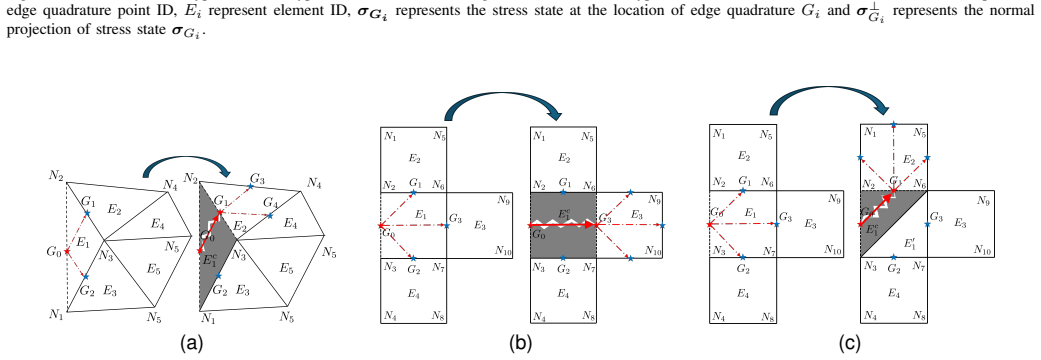
The load-bearing mechanism is the element-splitting algorithm implemented on the Edge-based Smoothed Finite Element Method (ES-FEM), in which strains are averaged over edge-based smoothing domains. Crack tips are identified with edge quadrature points; at each step the method enumerates the two candidate next tip locations in a triangle or the three in a quadrilateral, computes the candidate energy release rates through Eq. (24), and splits the element along the winning edge. The fracture criterion is the product of the normal-projected maximum principal stress at the candidate point and half the Heaviside-weighted stretch of the current crack-tip edge, so the only bookkeeping required is the evolving topology of split elements. This topology-based rule replaces the J-integral and turns crack advance into a local comparison with $G_c$.
What would settle it
Compute, in one simulated split, the actual drop in total potential energy of the entire domain divided by the area of the newly created crack surface, and compare it with the value of Eq. (24) that triggered the split; if the two disagree beyond discretization error, the energy-release-rate interpretation is falsified.
Extended reading notes
Core claim
The central discovery is that dynamic crack growth in quasi-brittle solids can be driven by a purely local, element-topology-based energy criterion instead of a path integral or a diffused damage field. When the crack tip sits at an edge quadrature point $G_0$ of an ES-FEM mesh, the method evaluates, for each candidate next edge point $G_i$, the quantity $G_{G_0} = \sigma^{\perp}_{G_i}\delta_d / 2$, where $\delta_d$ is the stretch of the current crack-tip edge and $\sigma^{\perp}_{G_i}$ is the component of the maximum principal stress at $G_i$ perpendicular to the candidate crack line. If $G_{G_0}$ exceeds the material's critical fracture energy release rate $G_c$, the crack advances to $G_i$; when a quadrilateral element is only partially split, it degenerates into triangle elements that continue the computation. The paper reports that this rule, without enrichment functions or a cohesive law, gives a shear-impact crack angle near 70 degrees, a critical notch-offset threshold of 0.765 versus the 0.77 measured in the concrete beam experiment, and curved PMMA crack paths matching reference simulations, with crack-tip speeds staying below roughly 60 percent of the Rayleigh wave speed.
Load-bearing premise
The load-bearing assumption is that Eq. (24) really measures the energy released per unit of new crack surface when the crack advances; the paper asserts this equality rather than deriving it from the variation of potential energy with crack area, and if it fails under mixed-mode dynamic loading the crack-advance decisions lose their energetic basis.
Editorial extensions
If this is right
- A coarse triangle mesh with 434 nodes still produces a shear-impact crack path near 70 degrees, so the method does not require the fine meshes that smeared crack approaches typically need.
- The critical notch offset 0.765 reproduces the measured 0.77 transition between pure mode-I and mixed-mode cracking in the concrete beam, without an artificially inserted mid-span notch.
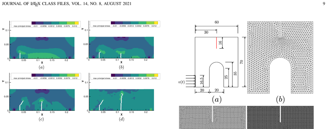
- In the PMMA compact compression case the curved arc-shaped crack path and the crack-tip speed history, peaking near 700 m/s and staying below about 60 percent of the Rayleigh wave speed, are reproduced with three different mesh densities.
- The same formulation captures mechanically and thermally induced crack propagation in a patterned Cu/ultra low-k interconnect layout, matching the qualitative failure patterns used as reference.
Reading between the lines
- Although Eq. (24) is built from a mode-I-style normal stress, it performs well on mixed-mode benchmarks; this suggests the opening component dominates in those cases, and a future sliding-mode term may be needed for shear-dominated crack growth.
- Because the method tracks only element topology, it could be combined with adaptive refinement of the band of elements near the crack tip, reducing cost further while preserving local stress resolution.
- The formula resembles a crack-closure estimate that needs no predefined crack path; if it survives broader validation, it could serve as a cheap screening tool for comparing interconnect layouts and crack-stop structures in chip-package interaction studies.
- The interconnect demonstration uses a periodic, conceptual layout, which hints that the method is cheap enough for statistical studies over many layout variants.
Signed reviews
Editorial analysis
A structured set of objections, weighed in public.
Referee Report
Summary. The paper proposes a Crack Element Method (CEM) implemented within the Edge-based Smoothed Finite Element Method (ES-FEM) framework. The method tracks dynamic crack growth in 2D quasi-brittle solids by splitting elements along edge-quadrature-point paths and by using a locally computed fracture energy release rate (Eq. 24) to decide whether and where a crack advances. The approach is demonstrated on three classical dynamic fracture benchmarks (Kalthoff-Winkler plate, three-point bending concrete beam, compact-compression PMMA specimen) and on two Cu/Ultra Low-k interconnect case studies, with comparisons to experimental data and reference numerical solutions for crack paths, dissipated energy, and crack tip velocity.
Significance. If the central criterion is accepted, the paper offers a practically attractive alternative to phase-field, XFEM, and cohesive-zone methods: it avoids remeshing and damage smearing, works on coarse meshes, and uses material fracture energies taken from the literature rather than fitted to the validation benchmarks. The benchmark coverage, including the Kalthoff crack angle near 70°, the transition parameter γ_t = 0.765 versus the experimental 0.77, and the curved PMMA crack path, is a genuine strength. However, the energetic meaning of the crack advance criterion is not established, and the reported crack-tip velocities show noteworthy mesh dependence. The method's practical value is plausible, but the theoretical status of Eq. (24) must be clarified before the central claim of an 'energy-based formulation' can be accepted.
major comments (4)
- [§III, Eq. (24)] The fracture energy release rate G_G0 = σ⊥_Gi · δd / 2 is presented as 'derived' from the topology of split elements, but no derivation from the variation of potential energy with respect to crack area (e.g., δL/δA or a crack-closure integral) is given. The quantity has the correct dimensions, yet the conjugacy is missing: δd (Eq. 23) is the stretch of the current crack-tip edge, while σ⊥_Gi is the normal projection of the maximum principal stress at a candidate edge quadrature point ahead of the tip. These are not the traction and opening associated with the same virtual crack extension. Since every crack advance decision in Eqs. (25) and (26) compares this quantity with G_c, and since the dissipated-energy comparisons in Figs. 7(a) and 13(a) inherit its meaning, the method's energy basis and its predicted direction and timing both hinge on Eq. (24) being a true energy release rate. The authors should either provide a proper derivation (e.g., from the discrete variation of the total potential energy when an element is split) or explicitly state that Eq. (24) is a heuristic criterion and then treat the benchmark agreement as empirical validation of that heuristic. As written, the claim that CEM is an 'energy-based formulation' is not supported.
- [§III, Eq. (24) and benchmarks IV.A–IV.C] Eq. (24) contains only the normal projection of the maximum principal stress and therefore has no explicit mode-II contribution. The Kalthoff-Winkler, three-point bending, and compact-compression problems are all mixed-mode to varying degrees, and the conclusion itself acknowledges that the formulation is based solely on mode-I fracture mechanics. If Eq. (24) is intended to represent the total energy release rate in mixed-mode conditions, the absence of shear traction work must be justified. If it is a mode-I-only criterion, then the good agreement with mixed-mode benchmark paths needs an explanation beyond the assertion in the conclusion, because the crack direction is selected by maximizing σ⊥ among candidate points, which is a maximum-principal-stress direction condition rather than an energy-balance direction condition.
- [§IV.A, Fig. 7(b)] The crack-tip velocity comparison shows a material mesh dependence: the regular fine mesh crack-tip velocity decreases after 35 µs, while the coarse and irregular meshes increase to about 1600 m/s. The authors offer a qualitative explanation (straighter path in the regular mesh), but the claim that CEM 'accurately captures' crack tip velocities requires a quantitative assessment: what is the spread relative to the reference solution, and is a 1600 m/s versus a decreasing velocity within the expected accuracy of the method? At minimum, the authors should provide the reference velocity data from [30] in the same plot and quantify the discrepancy.
- [§II.B, Eq. (17)] Equation (17) is labeled as a 'diagonal mass matrix' but the displayed expression is a consistent (non-diagonal) element mass matrix, since it is the outer product of shape function vectors integrated over the element. If a diagonal/lumped mass matrix is used in the explicit time integration of Eq. (20), the lumping scheme must be described or referenced. As written, the formulation is internally inconsistent: a non-diagonal mass matrix would not allow the 'without equation solving' statement following Eq. (20).
minor comments (6)
- [§III, Eq. (23)] The definition of δd uses the Heaviside function H(·) of (‖x_N2 − x_N1‖/‖X_N2 − X_N1‖ − 1). When the edge is in compression, δd = 0, so the criterion predicts no crack advance even under large compressive stretch along the edge. This should be stated and justified, as it affects the interpretation of the crack path under mixed-mode loading.
- [§II.B, Eq. (11)] The notation in Eq. (11) is confusing: the symbols N_gi^e, L_gi^e, M_Aj^n, and A_j are introduced in the text but the equation combines them in a way that is hard to parse. Please define all symbols directly below the equation and clarify the meaning of the quotient term (the area weight).
- [§III, Fig. 3(b) and text] There is a typo 'to to G3' in the description of crack pattern II in the QUAD element; also, the phrase 'from G0 to to G3' should read 'from G0 to G3.'
- [§IV.A] The text states that the crack angle in the proposed method is 'around 65°∼70°,' while the experimental value is 70°. Given that the crack path is digitized from figures, please provide a quantitative measurement of the final crack angle for each mesh and state the precise deviation from 70°.
- [§IV.D, mechanically-induced loads] The qualitative comparison between the simulated crack pattern and the fab image in Fig. 15(b) is not sufficient to 'confirm the ability of the proposed CEM to model the fracturing process.' A quantitative metric (e.g., crack path length, deviation from the layer interface, or comparison with a reference simulation) would strengthen the claim.
- [General] The manuscript contains several typographical errors: 'Possion' for 'Poisson,' 'detedction' for 'detection,' 'the reason why more energy is dissipated... may come from discrepancy' should be 'may come from the discrepancy,' and 'making it as a strong alternative' should be 'making it a strong alternative.' A careful proofread is recommended.
Assumptions & free parameters
free parameters (2)
- Time step Delta_t per benchmark =
e.g., 1e-8 s for the PMMA specimen, 0.1 micro-s for the concrete beam
- Mesh discretization (node/element counts) =
e.g., 434 to 14158 elements for the Kalthoff plate
assumptions (6)
- domain assumption Linear elastic, small-strain constitutive model with traction-free crack faces
- standard math Hamilton's principle and ES-FEM strain smoothing provide a valid weak form for the cracked domain
- ad hoc to paper Cracks can only advance from one edge quadrature point to another within a single element
- ad hoc to paper Eq. (24), G = sigma_perp * delta_d / 2, defines the fracture energy release rate
- domain assumption The maximum principal stress direction selects crack growth direction, with mode-II contributions neglected
- domain assumption Crack initiation at midspan in the concrete beam uses a tensile strength criterion
Cite this review
Pith. "Pith review of A Practical Finite Element Approach for Simulating Dynamic Crack Growth in Cu/Ultra Low-k Interconnect Structures." pith.science (2026). https://pith.science/paper/WH4YAH7U
@misc{pith2026250800193,
  author       = {Pith},
  title        = {Pith review of: A Practical Finite Element Approach for Simulating Dynamic Crack Growth in Cu/Ultra Low-k Interconnect Structures},
  year         = {2026},
  howpublished = {\url{https://pith.science/paper/WH4YAH7U}},
  note         = {Machine review of arXiv:2508.00193}
}
read the original abstract
This work presents a practical finite element modeling strategy, the Crack Element Method (CEM), for simulating the dynamic crack propagation in two-dimensional structures. The method employs an element-splitting algorithm based on the Edge-based Smoothed Finite Element Method (ES-FEM) to capture the element-wise crack growth while reducing the formation of poorly shaped elements that can compromise numerical accuracy and computational performance. A fracture energy release rate formulation is also developed based on the evolving topology of the split elements. The proposed approach is validated through a series of classical benchmark problems, demonstrating its accuracy and robustness in addressing dynamic fracture scenarios. Finally, the applicability of the CEM is illustrated in a case study involving patterned Cu/Ultra Low-k interconnect structures.
Figures


Figures from the paper (11 more)




Forward citations
Cited by 2 Pith papers
-
Revisit of Two-dimensional CEM on Crack Branching: from Single Crack-tip Tracking to Multiple Crack-tips Tracking
A multiple crack-tip tracking algorithm added to the 2D Crack Element Model reproduces crack branching and fragmentation in benchmark dynamic fracture tests.
-
A GPU-Accelerated Three-Dimensional Crack Element Method for Transient Dynamic Fracture Simulation
A 3D element-splitting method predicts dynamic crack paths and branching by removing elements whose computed fracture energy release rate exceeds a critical value, with GPU acceleration.
Reference graph
Works this paper leans on
-
[30]
Simulation of dynamic brittle and quasi-brittle fracture: a revisited local damage approach,
T. Q. Bui, H. T. Tran, X. Hu, and C. T. Wu, “Simulation of dynamic brittle and quasi-brittle fracture: a revisited local damage approach,” International Journal of Fracture , vol. 236, no. 1, pp. 59–85, 2022
work page 2022
-
[1]
K. Ravi-Chandar and W. G. Knauss, “An experimental investigation into dynamic fracture: Iii. on steady-state crack propagation and crack branching,” International Journal of fracture , vol. 26, pp. 141–154, 1984
work page 1984
-
[2]
T. L. Anderson and T. L. Anderson, Fracture mechanics: fundamentals and applications. CRC press, 2005
work page 2005
-
[3]
A. Grill, S. M. Gates, T. E. Ryan, S. V . Nguyen, and D. Priyadarshini, “Progress in the development and understanding of advanced low k and ultralow k dielectrics for very large-scale integrated interconnects—state of the art,” Applied Physics Reviews , vol. 1, no. 1, 2014
work page 2014
-
[4]
Chip-packaging interaction: a critical concern for cu/low k packaging,
G. Wang, P. S. Ho, and S. Groothuis, “Chip-packaging interaction: a critical concern for cu/low k packaging,” Microelectronics Reliability, vol. 45, no. 7-8, pp. 1079–1093, 2005
work page 2005
-
[5]
Chip-package interaction and crackstop study for cu/ultra low-k interconnects,
X. Zhang, R. S. Smith, R. Huang, and P. S. Ho, “Chip-package interaction and crackstop study for cu/ultra low-k interconnects,” in AIP Conference Proceedings , vol. 1143, no. 1. American Institute of Physics, 2009, pp. 197–203
work page 2009
-
[6]
A comparative study on finite element methods for dynamic fracture,
J.-H. Song, H. Wang, and T. Belytschko, “A comparative study on finite element methods for dynamic fracture,” Computational Mechanics, vol. 42, no. 2, pp. 239–250, 2008
work page 2008
-
[7]
C. T. Wu, N. Ma, K. Takada, and H. Okada, “A meshfree continuous– discontinuous approach for the ductile fracture modeling in explicit dynamics analysis,” Computational Mechanics, vol. 58, no. 3, pp. 391– 409, 2016
work page 2016
Show all 41 references
-
[8]
Modes of dynamic shear failure in solids,
J. F. Kalthoff, “Modes of dynamic shear failure in solids,” International Journal of fracture, vol. 101, pp. 1–31, 2000
2000
-
[9]
Modern topics and challenges in dynamic fracture,
B. N. Cox, H. Gao, D. Gross, and D. Rittel, “Modern topics and challenges in dynamic fracture,” Journal of the Mechanics and Physics of Solids, vol. 53, no. 3, pp. 565–596, 2005
2005
-
[10]
A rate-dependent hybrid phase field model for dynamic crack propagation,
D. H. Doan, T. Q. Bui, T. Van Do, and N. D. Duc, “A rate-dependent hybrid phase field model for dynamic crack propagation,” Journal of applied Physics, vol. 122, no. 11, 2017
2017
-
[11]
Vi. the phenomena of rupture and flow in solids,
A. A. Griffith, “Vi. the phenomena of rupture and flow in solids,” Philosophical transactions of the royal society of london. Series A, containing papers of a mathematical or physical character , vol. 221, no. 582-593, pp. 163–198, 1921
1921
-
[12]
A theory of crack initiation and growth in viscoelastic media: I. theoretical development,
R. A. Schapery, “A theory of crack initiation and growth in viscoelastic media: I. theoretical development,” International Journal of fracture , vol. 11, pp. 141–159, 1975
1975
-
[13]
Application of the crack layer theory to modeling of slow crack growth in polyethylene,
A. Chudnovsky and Y . Shulkin, “Application of the crack layer theory to modeling of slow crack growth in polyethylene,” International journal of fracture, vol. 97, pp. 83–102, 1999
1999
-
[14]
Finite element analysis of reinforced concrete beams,
D. Ngo and A. C. Scordelis, “Finite element analysis of reinforced concrete beams,” in Journal Proceedings, vol. 64, no. 3, 1967, pp. 152– 163
1967
-
[15]
Nonlinear analysis of reinforced concrete by the finite element method,
A. H. Nilson, “Nonlinear analysis of reinforced concrete by the finite element method,” in Journal Proceedings, vol. 65, no. 9, 1968, pp. 757– 766
1968
-
[16]
Ultimate strength analysis of prestressed concrete pres- sure vessels,
Y . R. Rashid, “Ultimate strength analysis of prestressed concrete pres- sure vessels,” Nuclear engineering and design , vol. 7, no. 4, pp. 334– 344, 1968
1968
-
[17]
Effect of finite element choice in blunt crack band analysis,
L. Cedolin and Z. P. Ba ˇzant, “Effect of finite element choice in blunt crack band analysis,” Computer Methods in Applied Mechanics and Engineering, vol. 24, no. 3, pp. 305–316, 1980
1980
-
[18]
Numerical analysis of elastic-plastic compression of pillars accounting for material hardening and softening,
S. Pietruszczak and Z. Mroz, “Numerical analysis of elastic-plastic compression of pillars accounting for material hardening and softening,” in International Journal of Rock Mechanics and Mining Sciences & Geomechanics Abstracts, vol. 17, no. 4. Elsevier, 1980, pp. 199–207
1980
-
[19]
An edge-based smoothed finite element method (es-fem) for static, free and forced vibration analyses of solids,
G. Liu, T. Nguyen-Thoi, and K. Lam, “An edge-based smoothed finite element method (es-fem) for static, free and forced vibration analyses of solids,” Journal of Sound and Vibration , vol. 320, no. 4-5, pp. 1100– 1130, 2009
2009
-
[20]
O. C. Zienkiewicz, R. L. Taylor, and J. Z. Zhu, The finite element method: its basis and fundamentals . Elsevier, 2005
2005
-
[21]
A finite element calculation of stress intensity factors by a modified crack closure integral,
E. F. Rybicki and M. F. Kanninen, “A finite element calculation of stress intensity factors by a modified crack closure integral,”Engineering fracture mechanics, vol. 9, no. 4, pp. 931–938, 1977
1977
-
[22]
The mathematical theory of equilibrium cracks in brittle fracture,
G. I. Barenblatt, “The mathematical theory of equilibrium cracks in brittle fracture,” Advances in applied mechanics , vol. 7, pp. 55–129, 1962
1962
-
[23]
Yielding of steel sheets containing slits,
D. S. Dugdale, “Yielding of steel sheets containing slits,” Journal of the Mechanics and Physics of Solids , vol. 8, no. 2, pp. 100–104, 1960
1960
-
[24]
The relation between crack growth resistance and fracture process parameters in elastic-plastic solids,
V . Tvergaard and J. W. Hutchinson, “The relation between crack growth resistance and fracture process parameters in elastic-plastic solids,” Journal of the Mechanics and Physics of Solids , vol. 40, no. 6, pp. 1377–1397, 1992
1992
-
[25]
A finite element method for crack growth without remeshing,
N. Mo ¨es, J. Dolbow, and T. Belytschko, “A finite element method for crack growth without remeshing,” International journal for numerical methods in engineering , vol. 46, no. 1, pp. 131–150, 1999
1999
-
[26]
Failure mode transition at high rates of shear loading,
J. Kalthoff, “Failure mode transition at high rates of shear loading,” Impact Load Dyn Behav Mater , vol. 1, p. 185, 1988
1988
-
[27]
Discontinuous modelling of shear bands using adaptive meshfree methods,
T. Rabczuk and E. Samaniego, “Discontinuous modelling of shear bands using adaptive meshfree methods,” Computer Methods in Applied Mechanics and Engineering , vol. 197, no. 6-8, pp. 641–658, 2008
2008
-
[28]
Cracking node method for dynamic fracture with finite elements,
J.-H. Song and T. Belytschko, “Cracking node method for dynamic fracture with finite elements,” International Journal for Numerical Methods in Engineering , vol. 77, no. 3, pp. 360–385, 2009
2009
-
[29]
A phase-field description of dynamic brittle fracture,
M. J. Borden, C. V . Verhoosel, M. A. Scott, T. J. Hughes, and C. M. Landis, “A phase-field description of dynamic brittle fracture,”Computer Methods in Applied Mechanics and Engineering , vol. 217, pp. 77–95, 2012
2012
-
[31]
Mixed-mode fracture of concrete subjected to impact loading,
R. John and S. P. Shah, “Mixed-mode fracture of concrete subjected to impact loading,” Journal of Structural Engineering , vol. 116, no. 3, pp. 585–602, 1990. JOURNAL OF LATEX CLASS FILES, VOL. 14, NO. 8, AUGUST 2021 14
1990
-
[32]
Element-free galerkin meth- ods for dynamic fracture in concrete,
T. Belytschko, D. Organ, and C. Gerlach, “Element-free galerkin meth- ods for dynamic fracture in concrete,” Computer Methods in Applied Mechanics and Engineering , vol. 187, no. 3-4, pp. 385–399, 2000
2000
-
[33]
The extended finite element method for dynamic fractures,
G. Zi, H. Chen, J. Xu, and T. Belytschko, “The extended finite element method for dynamic fractures,” Shock and Vibration, vol. 12, no. 1, pp. 9–23, 2005
2005
-
[34]
Three-dimensional cohesive modeling of dynamic mixed-mode fracture,
G. Ruiz, A. Pandolfi, and M. Ortiz, “Three-dimensional cohesive modeling of dynamic mixed-mode fracture,” International Journal for Numerical Methods in Engineering , vol. 52, no. 1-2, pp. 97–120, 2001
2001
-
[35]
An investigation of dynamic crack initiation in pmma,
D. Rittel and H. Maigre, “An investigation of dynamic crack initiation in pmma,” Mechanics of Materials , vol. 23, no. 3, pp. 229–239, 1996
1996
-
[36]
Adaptive dynamic cohesive fracture simulation using nodal perturbation and edge-swap operators,
G. H. Paulino, K. Park, W. Celes, and R. Espinha, “Adaptive dynamic cohesive fracture simulation using nodal perturbation and edge-swap operators,” International Journal for Numerical Methods in Engineering, vol. 84, no. 11, pp. 1303–1343, 2010
2010
-
[37]
A general mass lumping scheme for the variants of the extended finite element method,
I. Asareh, J.-H. Song, R. L. Mullen, and Y . Qian, “A general mass lumping scheme for the variants of the extended finite element method,” International Journal for Numerical Methods in Engineering , vol. 121, no. 10, pp. 2262–2284, 2020
2020
-
[38]
Mass lumping strategies for x-fem explicit dynamics: application to crack propagation,
T. Menouillard, J. R ´ethor´e, N. Moes, A. Combescure, and H. Bung, “Mass lumping strategies for x-fem explicit dynamics: application to crack propagation,” International Journal for Numerical Methods in Engineering, vol. 74, no. 3, pp. 447–474, 2008
2008
-
[39]
Efficient explicit time stepping for the extended finite element method (x-fem),
T. Menouillard, J. Rethore, A. Combescure, and H. Bung, “Efficient explicit time stepping for the extended finite element method (x-fem),” International Journal for Numerical Methods in Engineering , vol. 68, no. 9, pp. 911–939, 2006
2006
-
[40]
A nonlocal gradient damage model with energy limiter for dynamic brittle fracture,
H. T. Tran and T. Q. Bui, “A nonlocal gradient damage model with energy limiter for dynamic brittle fracture,” Computational Mechanics, vol. 73, no. 4, pp. 831–856, 2024
2024
-
[41]
Delamination of plasticized devices in dynamic service environments,
W. Tian, X. Chen, G. Zhang, Y . Chen, and J. Luo, “Delamination of plasticized devices in dynamic service environments,” Micromachines, vol. 15, no. 3, p. 376, 2024. Yuxi Xie received the B.S. degree in civil engineering from Huazhong University of Science and Technology, Wuha...
2024
Reviewed August 6, 2026 · model on record in the stance chip above.
Discussion (0). Continue with ORCID to comment.