Robust Path Following Control for Vehicles with Uncertain Steering Resistance Using Model Error Compensation
Pith reviewed 2026-05-10 02:14 UTC · model grok-4.3
The pith
Modeling steering resistance as a state with uncertain coefficient and compensating via Model Error Compensator reduces maximum path tracking error in vehicle simulations.
A machine-rendered reading of the paper's core claim, the machinery that carries it, and where it could break.
Core claim
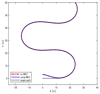
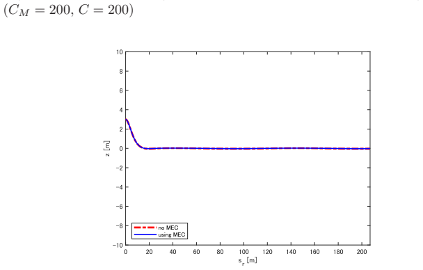
By including steering resistance explicitly in the dynamics, modeling it as a function of vehicle speed and steering angle, and compensating the resulting model error with a Model Error Compensator, the closed-loop system achieves smaller maximum lateral and heading errors than standard controllers when the resistance coefficient is unknown or mismatched.
What carries the argument
Model Error Compensator that cancels the disturbance arising from uncertainty in the scalar coefficient of the steering-resistance function.
If this is right
- The controller remains stable for a range of resistance-coefficient mismatches without requiring online identification.
- Path-tracking accuracy improves under constant but unknown road-surface conditions.
- The same compensation structure can be applied whenever actuator resistance appears as an uncertain multiplicative term.
- Explicit inclusion of resistance dynamics removes a systematic source of steady-state offset in curved-path following.
Where Pith is reading between the lines
- The method could be tested on hardware with measured tire-road friction changes to check whether the scalar assumption holds in practice.
- Combining the compensator with adaptive laws for the coefficient might further reduce residual error on surfaces that change during a maneuver.
- The same modeling choice could address other vehicle uncertainties such as load variation or actuator backlash if they admit a similar functional form.
Load-bearing premise
Steering resistance is fully captured by a known function of speed and angle whose only mismatch is a constant scalar that the compensator can remove without destabilizing the loop.
What would settle it
A simulation in which the true resistance deviates structurally from the assumed speed-and-angle form and either the peak tracking error fails to decrease or closed-loop poles move into the right half-plane.
Figures


read the original abstract
This paper presents a robust path following control method for vehicles that explicitly considers steering resistance dynamics to improve tracking accuracy. Conventional methods typically treat the steering angle as a direct control input; however, this approach introduces the steering angle as a state variable and incorporates the steering resistance effect into the control model. The steering resistance is modeled as a function of vehicle speed and steering angle, whereas in practice it varies depending on road conditions. To address the resulting model inaccuracies, a Model Error Compensator (MEC) is introduced, mitigating the effects of variations in steering resistance and enhancing the adaptability of the system to different environments. Since the steering resistance coefficient depends on road surface properties and is difficult to determine precisely, the proposed method treats it as an uncertain parameter and compensates for the resulting model error via MEC. Numerical simulations are conducted to evaluate the performance of the proposed method under varying degrees of parameter mismatch, demonstrating that the proposed method substantially reduces the maximum tracking error in representative mismatched cases compared to the conventional method. The results indicate that explicitly modeling steering resistance dynamics and compensating for model errors improve path following performance in numerical simulations compared to conventional approaches.
Editorial analysis
A structured set of objections, weighed in public.
Referee Report
Summary. The paper proposes a path-following controller for vehicles that augments the standard kinematic model by treating steering angle as a dynamic state and explicitly including steering resistance as a function of speed and steering angle scaled by an uncertain scalar coefficient k. A Model Error Compensator (MEC) is added as an outer correction layer to cancel the model error induced by mismatch in k. The central claim is that this MEC-augmented controller substantially reduces maximum path-tracking error relative to a conventional controller (that treats steering angle as a direct input) in numerical simulations under representative parameter mismatches.
Significance. If the simulations are representative and the closed-loop system remains stable for a useful range of k mismatch, the explicit modeling of steering resistance plus MEC compensation could provide a practical robustness layer for vehicle control under varying road conditions. The approach is conceptually straightforward and targets a real actuator uncertainty, but its significance is currently limited by the absence of analytical stability margins or exhaustive quantitative validation.
major comments (3)
- [Numerical Simulations] Numerical Simulations section: The headline claim that the proposed method 'substantially reduces the maximum tracking error in representative mismatched cases' is supported only by the statement that simulations were performed; no numerical values for max tracking error (proposed vs. conventional), no specific mismatch ratios |k/k_nom|, no vehicle parameters, no speed profiles, and no description of the baseline controller are supplied. This renders the quantitative performance gain uninspectable and non-reproducible.
- [Controller Design] Controller Design / Stability section: Robustness to arbitrary scalar mismatch in the steering resistance coefficient is asserted solely via selected simulations. No Lyapunov function, small-gain argument, or input-to-state stability (ISS) analysis is provided for the MEC-augmented error system when |k/k_nom| deviates from 1. Without such analysis, it is impossible to determine the interval of k for which path error remains bounded, which is load-bearing for the robustness conclusion.
- [Modeling] Modeling section: The steering resistance is stated to be modeled as k·f(v,δ) with k the sole uncertain parameter, yet the explicit functional form of f(v,δ) and the resulting state-space equations after substitution into the vehicle kinematics are not shown. This prevents verification that the MEC exactly cancels the model error term without introducing additional unstable dynamics.
minor comments (2)
- [Abstract] Abstract: The phrase 'steering resistance dynamics' is used before any equation is introduced; a forward reference to the modeling equation would improve readability.
- [Introduction] Notation: The symbol for the MEC gain or compensator transfer function is not defined in the abstract or early sections, making it difficult to follow how the compensation is implemented.
Simulated Author's Rebuttal
We thank the referee for the constructive and detailed comments, which highlight important areas for improving the clarity, reproducibility, and analytical support in our manuscript. We have addressed each major comment below and will incorporate the necessary revisions to strengthen the paper.
read point-by-point responses
-
Referee: [Numerical Simulations] Numerical Simulations section: The headline claim that the proposed method 'substantially reduces the maximum tracking error in representative mismatched cases' is supported only by the statement that simulations were performed; no numerical values for max tracking error (proposed vs. conventional), no specific mismatch ratios |k/k_nom|, no vehicle parameters, no speed profiles, and no description of the baseline controller are supplied. This renders the quantitative performance gain uninspectable and non-reproducible.
Authors: We agree that the simulation results in the current manuscript are described qualitatively and lack the quantitative details needed for reproducibility and independent verification. In the revised manuscript, we will expand the Numerical Simulations section to include explicit numerical values for the maximum path-tracking errors achieved by the proposed MEC-augmented controller versus the conventional method. We will also report the specific mismatch ratios tested (e.g., |k/k_nom| = 0.5, 0.8, 1.2, 1.5), the vehicle parameters employed, the speed profiles, and a complete description of the baseline controller. These additions will make the performance improvements transparent and allow readers to assess the gains directly. revision: yes
-
Referee: [Controller Design] Controller Design / Stability section: Robustness to arbitrary scalar mismatch in the steering resistance coefficient is asserted solely via selected simulations. No Lyapunov function, small-gain argument, or input-to-state stability (ISS) analysis is provided for the MEC-augmented error system when |k/k_nom| deviates from 1. Without such analysis, it is impossible to determine the interval of k for which path error remains bounded, which is load-bearing for the robustness conclusion.
Authors: We acknowledge that the manuscript demonstrates robustness to k mismatch exclusively through numerical simulations without supplying a formal Lyapunov, small-gain, or ISS analysis. A complete analytical characterization of the stability region for arbitrary mismatch is challenging given the nonlinear vehicle dynamics and the structure of the MEC. In the revision, we will augment the Controller Design section with an expanded discussion of the empirical stability margins observed across a broader set of simulation trials, explicitly stating the range of |k/k_nom| for which path error remains bounded. We will also outline the error-cancellation mechanism of the MEC and its implications for robustness, while noting the reliance on simulation-based validation as a practical complement to theory. revision: partial
-
Referee: [Modeling] Modeling section: The steering resistance is stated to be modeled as k·f(v,δ) with k the sole uncertain parameter, yet the explicit functional form of f(v,δ) and the resulting state-space equations after substitution into the vehicle kinematics are not shown. This prevents verification that the MEC exactly cancels the model error term without introducing additional unstable dynamics.
Authors: We apologize for the omission of these explicit details. The steering resistance term is defined as k·f(v,δ), where f(v,δ) captures the physical dependence on speed and steering angle. In the revised manuscript, we will provide the precise mathematical expression for f(v,δ) and derive the full state-space equations of the augmented kinematic model after substitution. This will enable readers to verify that the MEC is structured to cancel the model-error contribution δk·f(v,δ) as an additive correction without introducing new unstable modes in the closed-loop dynamics. revision: yes
Circularity Check
No circularity: MEC design and simulation results are independent of fitted inputs
full rationale
The paper introduces an explicit steering resistance model with a single uncertain scalar coefficient, then adds a separate Model Error Compensator layer to handle mismatch. Performance claims rest on numerical simulations comparing tracking error under representative mismatches, without any equation that defines the reported error reduction in terms of the same coefficient or MEC gain being fitted. No self-citations, uniqueness theorems, or ansatzes are used to justify the core architecture. The derivation chain therefore remains self-contained and externally falsifiable via the reported simulations.
Axiom & Free-Parameter Ledger
free parameters (1)
- steering resistance coefficient
axioms (1)
- domain assumption Steering resistance dynamics can be modeled as a function of vehicle speed and steering angle
invented entities (1)
-
Model Error Compensator (MEC)
no independent evidence
Reference graph
Works this paper leans on
-
[1]
Critical Reasons for Crashes Investigated in the Nat ional Motor Vehicle Crash Causation Survey,
S. Singh, “Critical Reasons for Crashes Investigated in the Nat ional Motor Vehicle Crash Causation Survey,” Traffic Safety Facts Crash Stats , Report No. DOT HS 812 506, National Highway Traffic Safety Administration, Washington, DC, 2018
work page 2018
-
[2]
A Surv ey of Au- tonomous Driving: Common Practices and Emerging Technologies,
E. Yurtsever, J. Lambert, A. Carballo, and K. Takeda, “A Surv ey of Au- tonomous Driving: Common Practices and Emerging Technologies,” IEEE Access, Vol. 8, pp. 58443–58469, 2020
work page 2020
-
[3]
A. P. Aguiar and J. P. Hespanha, “Trajectory-Tracking and Pa th-Following of Underactuated Autonomous Vehicles with Parametric Modeling Un cer- tainty,” IEEE Transactions on Automatic Control, Vol. 52, No. 8, pp. 1362– 1379, 2007
work page 2007
-
[4]
Time-varying path following contr ol for port-Hamiltonian systems,
M. Taniguchi and K. Fujimoto, “Time-varying path following contr ol for port-Hamiltonian systems,” Transactions of the Society of Instrument and Control Engineers, Vol. 47, No. 3, pp. 141–149, 2011
work page 2011
-
[5]
Nested PID steering contro l for lane keeping in autonomous vehicles,
R. Marino, S. Scalzi, and M. Netto, “Nested PID steering contro l for lane keeping in autonomous vehicles,” Control Engineering Practice , Vol. 19, No. 12, pp. 1459–1467, 2011
work page 2011
-
[6]
G. Oriolo, A. De Luca, and M. Vendittelli, “WMR Control via Dynamic Feedback Linearization: Design, Implementation, and Experimenta l Vali- dation,” IEEE Transactions on Control Systems Technology , Vol. 10, No. 6, pp. 835–852, 2002
work page 2002
-
[7]
Arbitrary Pa th Tracking Control of Articulated Vehicles Using Nonlinear Control Th eory,
M. Sampei, T. Tamura, T. Kobayashi, and N. Shibui, “Arbitrary Pa th Tracking Control of Articulated Vehicles Using Nonlinear Control Th eory,” IEEE Transactions on Control Systems Technology , Vol. 3, No. 1, pp. 125– 131, 1995
work page 1995
-
[8]
O. Koyama, K. Sekiguchi, and K. Nonaka, “Path-following Contro l for Ve- hicles Based on Time-state Control Form Using Travel Distance as a Virtual Time-axis –Applying to model Predictive Parking Control–,” Transactions of the Society of Instrument and Control Engineers , Vol. 50, No. 10, pp. 746–754, 2014
work page 2014
-
[9]
Optimal Velocity Control Met hod in Path Following Control Problem,
H. Okajima, T. Asai, and S. Kawaji, “Optimal Velocity Control Met hod in Path Following Control Problem,” Proc. of the 17th IF AC World Congress , pp. 90–95, 2008 27
work page 2008
-
[10]
Robust Path Following Control B ased on Model Error Compensator,
H. Okajima and N. Matsunaga, “Robust Path Following Control B ased on Model Error Compensator,” Journal of the Institute of Systems, Control and Information Engineers , Vol. 29, No. 10, pp. 466–468, 2016
work page 2016
-
[11]
A Feedback Linea rization Method for Non-linear Control Systems Based on Model Error Com pen- sator,
H. Okajima, Y. Nishimura, and N. Matsunaga, “A Feedback Linea rization Method for Non-linear Control Systems Based on Model Error Com pen- sator,” Transactions of the Society of Instrument and Control Engin eers, Vol. 50, No. 12, pp. 869–874, 2014
work page 2014
-
[12]
S. Vougioukas, “Agricultural Robotics,” Annual Review of Control, Robotics, and Autonomous System , Vol. 2, pp. 365–392, 2019
work page 2019
-
[13]
Following a Path of Varying Curvature as an Output R egula- tion Problem,
C. Altafini, “Following a Path of Varying Curvature as an Output R egula- tion Problem,” IEEE Transactions on Automatic Control , Vol. 47, No. 9, pp. 1551–1556, 2002
work page 2002
-
[14]
Path Following With Reduced Off-Tracking for Multibod y Wheeled Vehicles,
C. Altafini, “Path Following With Reduced Off-Tracking for Multibod y Wheeled Vehicles,” IEEE Transactions on Control Systems Technology , Vol. 11, No. 4, pp. 598–605, 2003
work page 2003
-
[15]
Application of Autonomous Driving Device to Rough Road Durability Test,
S.Tanabe, M.Miyamoto, N.Yamagami, A.Yamahiro, S.Moritomo, and H.Kamimura, “Application of Autonomous Driving Device to Rough Road Durability Test,” Mazda Technical Review, vol. 37, pp. 39–44, 2020
work page 2020
-
[16]
Analysis of Steering Torque Input Based on Simple Model for Motorcycles,
J. Hirasawa, “Analysis of Steering Torque Input Based on Simple Model for Motorcycles,” Proceedings of the Society of Automotive Engineers of Japan, Vol. 51, No. 3, pp. 434–440, 2020
work page 2020
-
[17]
Theoretical Study of Steering Effort —using Auto sim—,
I. R. Park, “Theoretical Study of Steering Effort —using Auto sim—,” Seoul 2000 FISITA World Automotive Congress , 2000
work page 2000
-
[18]
Model Error Compensator for adding Robustnes s toward Existing Control Systems,
H. Okajima, “Model Error Compensator for adding Robustnes s toward Existing Control Systems,” IF AC-PapersOnLine, Vol. 56, No. 2, pp. 3622– 3629, 2023
work page 2023
-
[19]
Disturbance-Observer- Based Con- trol and Related Methods-An Overview,
W. Chen, J. Yang, L. Guo, and S. Li, “Disturbance-Observer- Based Con- trol and Related Methods-An Overview,” IEEE Transactions on Industrial Electronics, Vol. 63, No. 2, pp. 1083–1095, 2016
work page 2016
-
[20]
Disturbance Observer-B ased Ro- bust Control and Its Applications: 35th Anniversary Overview,
E. Sariyildiz, R. Oboe, and K. Ohnishi, “Disturbance Observer-B ased Ro- bust Control and Its Applications: 35th Anniversary Overview,” IEEE Transactions on Industrial Electronics , Vol. 67, No. 3, pp. 2042–2053, 2020
work page 2042
-
[21]
A Theoretical Model of Spee d- Dependent Steering Torque for Rolling Tyres,
Y. Wei, C. Oertel, Y. Liu, and X. Li, “A Theoretical Model of Spee d- Dependent Steering Torque for Rolling Tyres,” Vehicle System Dynamics , Vol. 54, No. 4, pp. 463–473, 2016 28
work page 2016
discussion (0)
Sign in with ORCID, Apple, or X to comment. Anyone can read and Pith papers without signing in.