REVIEW 2 minor 29 references
Multiport antenna arrays have 22 parameters with values invariant under excitation changes and lossless port embeddings.
Reviewed by Pith at T0; open to challenge. T0 means a machine referee read the full paper against a public rubric. the ladder, T0–T4 →
T0 review · grok-4.3
2026-06-28 07:36 UTC pith:LIV7YHM5
load-bearing objection This paper reviews 22 multiport antenna parameters and derives two invariances that follow from linearity and passivity, with concrete examples on simple dipole arrays.
The Gains, Effective Areas and Equivalent Areas of a Multiport Antenna Array
The pith
A machine-rendered reading of the paper's core claim, the machinery that carries it, and where it could break.
Core claim
The central claim is that certain gains, effective areas and equivalent areas of a multiport antenna array remain unchanged when the excitation variable is altered or when the array ports are subjected to an invertible lossless linear embedding, so that 14 of the emission parameters and all 8 reception parameters become independent of the specific choice of excitation description or port connection.
What carries the argument
Invariance under a change of excitation variable together with invariance under an invertible lossless linear embedding of the MAA ports.
Load-bearing premise
The 22 parameters can be separated into excitation-dependent and excitation-independent groups and the two 6-port parallel-dipole arrays are representative of general multiport arrays.
What would settle it
Explicit computation of the 22 parameters for a third multiport array with a different geometry or port count where the reported invariances fail to appear.
If this is right
- The 10 excitation-independent emission parameters and 8 reception parameters can be used for consistent comparisons across different excitation conventions.
- Passive linear embeddings do not alter the values of the invariant parameters, so equivalent-area definitions remain the same after lossless port transformations.
- The four excitation-dependent parameters change in a controlled way under the variable change, allowing direct translation between different authors' formulations.
- For the two 6-port dipole examples the computed numerical values satisfy both invariances exactly.
Where Pith is reading between the lines
- The same invariance structure might apply to active embeddings or to arrays with mutual coupling beyond the dipole cases examined.
- Design procedures could focus only on the 18 invariant parameters when comparing alternative feed networks.
- The separation into dependent and independent parameters may link to properties of the scattering matrix or the impedance matrix of the array.
Editorial analysis
A structured set of objections, weighed in public.
Referee Report
Summary. The manuscript reviews the definitions of 22 parameters of a multiport antenna array (MAA) in a specified direction—4 excitation-dependent parameters for emission, 10 excitation-independent parameters for emission, and 8 parameters for reception—concisely stating their properties. It computes and discusses the parameters for two simple 6-port parallel-dipole arrays, derives an invariance under a change of excitation variable (allowing comparison with parameters used by other authors), and identifies an invariance under an invertible lossless linear embedding of the MAA ports.
Significance. If the derivations hold, the work supplies a unified review of gain, effective-area, and equivalent-area parameters for multiport arrays together with two explicit invariances obtained from change-of-variable and embedding arguments. The concrete computations on the dipole arrays provide verifiable illustrations, and the separation into excitation-dependent and independent categories follows directly from standard linearity and passivity assumptions. This framework may reduce ambiguity when different authors adopt different excitation normalizations or port transformations.
minor comments (2)
- The abstract states that the parameters are computed for the two 6-port arrays but supplies no numerical values, tables, or equations; adding at least one representative result (e.g., a table of the 22 quantities for one array) would make the central claims immediately verifiable.
- [Examples] The claim that the two 6-port dipole arrays serve only as illustrations is stated, yet the text should explicitly note whether any invariance result depends on the specific geometry or holds for arbitrary passive linear embeddings.
Simulated Author's Rebuttal
We thank the referee for the positive summary, significance assessment, and recommendation of minor revision. No specific major comments were listed in the report.
Circularity Check
No significant circularity identified
full rationale
The paper reviews definitions of 22 standard antenna parameters (4 excitation-dependent, 10 independent for emission, 8 for reception) drawn from established electromagnetic theory, then derives two invariances directly from the effect of a change of excitation variable and from passive linear embeddings of ports. These steps follow from the reviewed definitions plus linearity and passivity assumptions; the two 6-port dipole arrays serve only as concrete numerical illustrations, not as fitted data. No parameters are obtained by fitting and then relabeled as predictions, no self-definitional loops appear in the equations, and comparisons are made with parameters used by other authors rather than load-bearing self-citations. The derivation chain is therefore self-contained against external benchmarks and does not reduce to its inputs by construction.
Axiom & Free-Parameter Ledger
read the original abstract
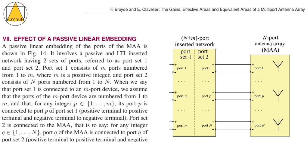
We review the definitions of 22 parameters of a multiport antenna array operating in a specified direction: 4 excitation-dependent parameters for emission, 10 excitation-independent parameters for emission, and 8 parameters for reception. We concisely set forth their main properties. As examples, we compute and discuss these parameters in the cases of two simple 6-port antenna arrays made of parallel dipole antennas. We investigate the effect of a change of variable describing the excitation during emission. This allows us to find an ``invariance under a change of excitation variable'', and to compare some of the parameters with the ones used by other authors. We study passive linear embeddings of the MAA ports, to reveal an ``invariance under an invertible lossless linear embedding''.
Figures


Reference graph
Works this paper leans on
-
[1]
Embedded element patterns and mutual impedance matrices in the terminated phased array environment,
D.F. Kelley, “Embedded element patterns and mutual impedance matrices in the terminated phased array environment,” Proc. 2005 IEEE Antennas and Propagation Society Int. Symp. , vol. 3, pp. 659–662, Jul. 2005
2005
-
[2]
About the Gains and the Effective Areas of a Multiport Antenna Array,
F. Broydé and E. Clavelier, “About the Gains and the Effective Areas of a Multiport Antenna Array,” Excem Research Papers in Electronics and Electromagnetics, no. 10, doi: 10.5281/zenodo.14584381, Jan. 2025
-
[3]
Genève, Switzerland: IEC, 1992
IEC 60050-712, First Edition (1992-04), International Electrotechnical V ocabulary (IEV) - Part 712: Antennas . Genève, Switzerland: IEC, 1992
1992
-
[4]
Genève, Switzerland: IEC, 2021
IEC 60050-712, Amendment 1 (2021-04), International Electrotechnical V ocabulary (IEV) - Part 712: Antennas . Genève, Switzerland: IEC, 2021
2021
-
[5]
About the Power Ratios Relevant to a Passive Linear Time-Invariant 2-Port,
F. Broydé and E. Clavelier, “About the Power Ratios Relevant to a Passive Linear Time-Invariant 2-Port,” Excem Research Papers in Electronics and Electromagnetics, no. 5, doi: 10.5281/zenodo.6555682, May 2022
-
[6]
Some Results on Power in Passive Linear Time-Invariant Multiports, Part 3,
F. Broydé and E. Clavelier, “Some Results on Power in Passive Linear Time-Invariant Multiports, Part 3,” Excem Research Papers in Electronics and Electromagnetics, no. 7, doi: 10.5281/zenodo.8124511, Jul. 2023
-
[7]
The Radiation and Transducer Efficiencies of a Multiport Antenna Array,
F. Broydé and E. Clavelier, “The Radiation and Transducer Efficiencies of a Multiport Antenna Array,” Excem Research Papers in Electronics and Electromagnetics, no. 4, doi: 10.5281/zenodo.5816837, Jan. 2022
-
[8]
Kobayashi, Code for publication in Zenodo, 10.5281/zen- odo.21216656 (2026)
F. Broydé and E. Clavelier, “The Expected V alue of a Generalized Rayleigh Ratio, with Circuits and Antennas in Mind,” Excem Research Papers in Electronics and Electromagnetics , no. 11, doi: 10.5281/zen- odo.15568357, Jun. 2025
-
[9]
Im- plementing Two Generalizations of the Friis Transmission Formula,
F. Broydé, E. Clavelier, L. Jelinek, M. Capek and K.F. Warnick “Im- plementing Two Generalizations of the Friis Transmission Formula,” Excem Research Papers in Electronics and Electromagnetics , no. 8, doi: 10.5281/zenodo.10448398, Jan. 2024
-
[10]
Gen- eralized Friis transmission formula for multiport antenna arrays,
L. Jelinek, M. Capek, E. Clavelier, K.F. Warnick and F. Broydé, “Gen- eralized Friis transmission formula for multiport antenna arrays,” Proc. 2024 IEEE Int. Symp. on Antennas and Propagation and INC-USNC-URSI Radio Science Meeting, Jul. 2024
2024
-
[11]
General- ized Friis transmission formula using active antenna available power and unnamed power gain,
K.F. Warnick, F. Broydé, L. Jelinek, M. Capek and E. Clavelier, “General- ized Friis transmission formula using active antenna available power and unnamed power gain,” IEEE Trans. Antennas Propag. , vol. 72, no. 8, pp. 6321-6331, Aug. 2024
2024
-
[12]
Some Results on Power in Passive Linear Time-Invariant Multiports, Part 2,
F. Broydé and E. Clavelier, “Some Results on Power in Passive Linear Time-Invariant Multiports, Part 2,” Excem Research Papers in Electronics and Electromagnetics, no. 3, doi: 10.5281/zenodo.4683896, Apr. 2021
-
[13]
The scattering matrix in network theory
H.J. Carlin, “The scattering matrix in network theory”, IRE Trans. Circuit Theory, vol. 3, no. 2, pp. 88-97, Jun. 1956
1956
-
[14]
Power waves and the scattering matrix
K. Kurokawa, “Power waves and the scattering matrix”, IEEE Trans. Microw. Theory Tech. , vol. 13, no. 2, pp. 194-202, Mar. 1965
1965
-
[15]
Llorente-Romano, A
S. Llorente-Romano, A. Garca-Lampérez, T.K. Sarkar and M. Salazar- Palma, “An exposition on the choice of the proper S parameters in characterizing devices including transmission lines with complex refer- ence impedances and a general methodology for computing them," IEEE Antennas Propag. Mag. , vol. 55, no. 4, pp. 94-112, Aug. 2013
2013
-
[16]
Some Results on Power in Passive Linear Time-Invariant Multiports, Part 1,
F. Broydé and E. Clavelier, “Some Results on Power in Passive Linear Time-Invariant Multiports, Part 1,” Excem Research Papers in Electronics and Electromagnetics, no. 2, doi: 10.5281/zenodo.4419637, Jan. 2021
-
[17]
A modal description of multiport antennas,
J.J. Lynch, “A modal description of multiport antennas,” International Journal of Antennas and Propagation , vol. 2011, article ID 438437, 2011
2011
-
[18]
IEEE Std 145-2013, IEEE Standard for Definitions of Terms for Antennas , New Y ork, NY , USA: IEEE, 2014
2013
-
[19]
Finding optimal total active re- flection coefficient and realized gain for multi-port lossy antennas,
M. Capek, L. Jelinek and M. Masek, “Finding optimal total active re- flection coefficient and realized gain for multi-port lossy antennas,” IEEE Trans. Antennas Propag. , vol. 69, no. 5, pp. 2481–2493, May 2021
2021
-
[20]
Maximizing indepen- dent channels and efficiency in BTS array antennas via EM degrees of freedom,
F. Puggelli, B. Biscontini, E. Martini and S. Maci, “Maximizing indepen- dent channels and efficiency in BTS array antennas via EM degrees of freedom,” IEEE Trans. Antennas Propag. , vol. 73, no. 6, pp. 3444-3458, Jun. 2025
2025
-
[21]
Haus and R.B
H.A. Haus and R.B. Adler, Circuit Theory of Linear Noisy Networks , New Y ork, NY , USA: John Wiley & Sons, 1959
1959
-
[22]
Horn and C.R
R.A. Horn and C.R. Johnson, Matrix Analysis , 2nd ed., New Y ork, NY , USA: Cambridge University Press, 2013
2013
-
[23]
The maximum power transfer theorem for n-ports,
C.A. Desoer, “The maximum power transfer theorem for n-ports,” IEEE Trans. Circuit Theory , vol. 20, no. 3, pp. 328-330, May 1973
1973
-
[24]
Miniaturized antenna arrays using decoupling networks with realistic elements,
J. Weber, C. V olmer, K. Blau, R. Stephan and M.A. Hein, “Miniaturized antenna arrays using decoupling networks with realistic elements,” IEEE Trans. Microw. Theory Tech. , vol. 54, no. 6, pp. 2733-2740, Jun. 2006
2006
-
[25]
Hecht, Optics, 4th ed., International Edition, San Francisco, CA, USA: Addison Wesley, 2002
E. Hecht, Optics, 4th ed., International Edition, San Francisco, CA, USA: Addison Wesley, 2002
2002
-
[26]
Collin, Antennas and Radiowave Propagation , International Edition, New Y ork, NY , USA: McGraw-Hill, 1985
R.E. Collin, Antennas and Radiowave Propagation , International Edition, New Y ork, NY , USA: McGraw-Hill, 1985
1985
-
[27]
Orfanidis, Electromagnetic Waves and Antennas — vol
S.J. Orfanidis, Electromagnetic Waves and Antennas — vol. 2 — Antennas , Sophocles J. Orfanidis, 2016. FRÉDÉRIC BROYDÉ was born in France in
2016
-
[28]
degree in physics engineering from the Ecole Nationale Supérieure d’Ingénieurs Electriciens de Grenoble (ENSIEG) and the Ph.D
He received the M.S. degree in physics engineering from the Ecole Nationale Supérieure d’Ingénieurs Electriciens de Grenoble (ENSIEG) and the Ph.D. in microwaves and microtechnolo- gies from the Université des Sciences et Technolo- gies de Lille (USTL). He co-founded the Excem corporation in May 1988, a company providing engineering and re- search and dev...
1988
-
[29]
degree in physics engineering from the Ecole Nationale Supérieure d’Ingénieurs Electriciens de Grenoble (ENSIEG)
She received the M.S. degree in physics engineering from the Ecole Nationale Supérieure d’Ingénieurs Electriciens de Grenoble (ENSIEG). She is co-founder of the Excem corporation, based in Maule, France, and she is currently CEO of Excem. She is also president of Tekcem, a company selling or licensing intellectual property rights to foster research. She i...
1988
discussion (0)
Sign in with ORCID, Apple, or X to comment. Anyone can read and Pith papers without signing in.