Round-Robin Test of a Light-Emitting Electrochemical Cell: Establishing a Reference Protocol for Quality Research
Pith reviewed 2026-06-29 10:03 UTC · model grok-4.3
The pith
A shared protocol for light-emitting electrochemical cells produces reproducible good performance across nine labs.
A machine-rendered reading of the paper's core claim, the machinery that carries it, and where it could break.
Core claim
We present a LEC reference protocol which details the sourcing of materials and the procedures and parameters for robust device fabrication and operation. The protocol has been tested across nine international research groups, and the collected results from this interlaboratory round-robin test confirm that good LEC performance can be reproducibly obtained following our protocol. We also identify common pitfalls that can arise during LEC development and present practical steps for attaining optimum LEC performance.
What carries the argument
The LEC reference protocol specifying material sourcing, fabrication parameters, and operation instructions for light-emitting electrochemical cells.
Load-bearing premise
The protocol supplies enough detail on materials, fabrication, and operation that differences in lab equipment, environment, or operator skill will not block reproducible good performance.
What would settle it
A tenth lab follows every listed step exactly yet obtains markedly lower performance metrics than the round-robin average.
Figures
read the original abstract
Emerging technologies benefit from a jointly established reference protocol, which can lower the bar of entry for new researchers while serving as a calibration standard for established actors. The light-emitting electrochemical cell (LEC) combines electrochemistry and optoelectronics in an intricate manner, and it can by that enable sustainable and commercially relevant printing fabrication of emissive thin-film devices. However, LEC performance is sensitive to a range of material and processing parameters, which frequently results in inadequate, or even erroneous, device evaluation. With this in mind, we present herein a LEC reference protocol, which details the sourcing of materials and the procedures and parameters for robust device fabrication and operation. The protocol has been tested across nine international research groups, and the collected results from this interlaboratory round-robin test confirm that good LEC performance can be reproducibly obtained following our protocol. We also identify common pitfalls that can arise during LEC development, and present practical steps for attaining optimum LEC performance. We hope this reference protocol will improve the quality of future LEC research and serve as a guide for future researchers entering this vibrant field.
Editorial analysis
A structured set of objections, weighed in public.
Referee Report
Summary. The paper presents a reference protocol for the sourcing of materials, fabrication, and operation of light-emitting electrochemical cells (LECs). It reports results from an interlaboratory round-robin test conducted across nine international research groups, claiming that this test confirms reproducible attainment of good LEC performance when the protocol is followed. The authors additionally identify common pitfalls and practical steps for optimal device performance.
Significance. If the central empirical claim holds, the work is significant for an emerging optoelectronic technology whose performance is known to be sensitive to many material and processing variables. A multi-lab validation of a complete protocol provides a concrete calibration standard and lowers the barrier for new entrants, which is a recognized need in the field. Credit is due for organizing and executing the round-robin study itself, which directly tests the completeness of the protocol instructions.
major comments (1)
- [Round-robin test results] The abstract and main text assert that the interlaboratory round-robin test produced consistent good performance across nine groups. However, the manuscript does not include the full dataset, individual-lab results, or quantitative error statistics (e.g., standard deviation in luminance or efficiency). This omission makes it impossible to evaluate whether post-hoc exclusions or uncontrolled variables influenced the outcome and is therefore load-bearing for the reproducibility claim.
minor comments (1)
- [Protocol description] The quantitative thresholds used to define 'good LEC performance' (luminance, efficiency, lifetime, etc.) should be stated explicitly in the protocol section so that readers can directly compare the round-robin outcomes against those criteria.
Simulated Author's Rebuttal
We thank the referee for their positive evaluation of the work and for the constructive comment on the round-robin results. We address the point below.
read point-by-point responses
-
Referee: [Round-robin test results] The abstract and main text assert that the interlaboratory round-robin test produced consistent good performance across nine groups. However, the manuscript does not include the full dataset, individual-lab results, or quantitative error statistics (e.g., standard deviation in luminance or efficiency). This omission makes it impossible to evaluate whether post-hoc exclusions or uncontrolled variables influenced the outcome and is therefore load-bearing for the reproducibility claim.
Authors: We agree that the absence of the full per-lab dataset and quantitative error statistics limits the ability to independently assess the reproducibility claim. In the revised manuscript we will add a supplementary table that reports the key performance metrics (luminance, efficiency, and lifetime) obtained by each of the nine laboratories, together with the calculated mean values and standard deviations across the round-robin. This addition will make the consistency of the results transparent and allow readers to evaluate possible influences of uncontrolled variables. revision: yes
Circularity Check
No significant circularity
full rationale
The paper reports an empirical round-robin validation of a fabrication and operation protocol for LECs across nine independent labs. No derivations, equations, fitted models, or first-principles predictions appear in the work. The central claim—that good performance is reproducibly obtained when the protocol is followed—is directly tested by the interlaboratory data collection itself and does not reduce to any self-citation, ansatz, or input-by-construction. Self-citations, if present, are not load-bearing for the reproducibility result.
Axiom & Free-Parameter Ledger
Reference graph
Works this paper leans on
-
[1]
Active-material constituents The active material (AM) comprises three constituents:
-
[2]
The fluorescent conjugated polymer Super Yellow (SY, Merck, Mn >400.000 g mol-1, CAS: 26009-24-5)
-
[3]
The ion-transporter hydroxyl-capped trimethylolpropane ethoxylate (TMPE -OH, Merck, Mn = 1014 g mol-1, CAS: 50586-59-9)
-
[4]
TMPE-OH is dried in a vacuum oven at T = 50 °C for ≥ 12 h, and KCF3SO3 is dried in a vacuum oven at T = 190 °C for ≥ 16 h at pre-vacuum conditions (< 10- 3 bar)
The salt potassium trifluoromethanesulfonate (KCF 3SO3, Solvionic, purity ≥99.5%, CAS: 2926-27-4) SY is used as received from the vendor. TMPE-OH is dried in a vacuum oven at T = 50 °C for ≥ 12 h, and KCF3SO3 is dried in a vacuum oven at T = 190 °C for ≥ 16 h at pre-vacuum conditions (< 10- 3 bar). All three AM constituents (SY after delivery, and TMPE -O...
-
[5]
The ITO-coated glass substrate is cleaned by sequential 10-min sonication in: (i) detergent in deionized (DI) water, (ii) DI water, (iii) acetone, and (iv) isopropanol
Substrate The indium -tin-oxide (ITO) coated glass substrate features the following metrics: ITO sheet resistance ≤ 20 Ohm/square, optical transparency ≥ 85 % at = 555 nm, glass area = 3 -10 cm2, glass thickness ~1 mm. The ITO-coated glass substrate is cleaned by sequential 10-min sonication in: (i) detergent in deionized (DI) water, (ii) DI water, (iii...
-
[6]
A clean magnetic stirring rod of appropriate size (i.e
Master solutions Three vials are cleaned by sonication in acetone, followed by drying at T > 100 °C for ≥ 1 h in an oven. A clean magnetic stirring rod of appropriate size (i.e. with its long axis slightly smaller than the inner diameter of the vial) is inserted into each vial. All subsequent preparation steps are preferably performed in an inert-atmosphe...
-
[7]
Note 1: The time for dissolution of SY depends on the SY grain density and may take significantly longer than 24 h
KCF3SO3: 10 g l-1 The three master solutions are stirred on a hot plate at T = 70 °C for ≥ 24 h. Note 1: The time for dissolution of SY depends on the SY grain density and may take significantly longer than 24 h. Thus, make sure that SY is completely dissolved before moving to the next step. This can be probed by shaking the vial lightly and observing for...
-
[8]
Note: This is the solute (and not the solution) mass ratio
AM-ink The three master solutions are mixed to form the AM-ink with a SY:TMPE-OH:KCF3SO3 mass ratio of 1:0.1:0.03. Note: This is the solute (and not the solution) mass ratio. Since the SY solution is very viscous (and therefore essentially impossible to accurately pipette), the procedure is that the appropriate volumes of the TMPE-OH and KCF3SO3 master so...
-
[9]
The spin-coated AM film is protected from dust by a cover lid and dried on a hot plate at T = 70 °C for 1 h
AM film fabrication The AM-ink (at T 20 °C) is deposited on top of the ITO -coated substrate so that it covers the entire substrate area, and thereafter spin-coated at 2000 rpm (acceleration = 2000 rpm s -1) for 60 s. The spin-coated AM film is protected from dust by a cover lid and dried on a hot plate at T = 70 °C for 1 h. Note 1: Do not dry the AM fi...
2000
-
[10]
The Al electrode is deposited on top of the AM film to a thickness of 100 nm by thermal evaporation at a base pressure of < 5×10 -6 mbar
Top electrode fabrication The Al top electrode should preferably be deposited immediately after the drying of the AM film, but at the latest within 12 h. The Al electrode is deposited on top of the AM film to a thickness of 100 nm by thermal evaporation at a base pressure of < 5×10 -6 mbar. An evaporation shutter shall protect the AM film during the initi...
-
[11]
the turn -on measurement
Device characterization The characterization must be performed on pristine (i.e. non -biased) LEC devices, and it should be executed within 24 h of their fabrication. This measurement can either be executed on non - encapsulated LEC devices inside an inert -atmosphere glove box ([O 2], [H 2O] < 1 ppm) or on appropriately glass-encapsulated devices under a...
-
[12]
Material purchase and preparation The active material comprises three constituents, purchased from Sigma-Aldrich and Solvionic:
-
[13]
The emissive polymer Super Yellow (SY) (Sigma-Aldrich, CAS: 26009-24-5)
-
[14]
The ion transporter hydroxyl-capped trimethylolpropane ethoxylate (TMPE-OH) (Sigma-Aldrich, CAS: 50586-59-9, Mn = 1014 g/mol) o If the expected delivery time is too long, we can provide this material
-
[15]
Dry TMPE-OH in a vacuum oven at 50 °C for ≥ 12 h
The salt potassium trifluoromethanesulfonate (KCF3SO3) (Solvionic, purity ≥ 99.5%, CAS: 2926-27-4) Use SY as received. Dry TMPE-OH in a vacuum oven at 50 °C for ≥ 12 h. Dry KCF3SO3 in a vacuum oven at 190 °C for ≥ 16 h. Store the dried TMPE-OH, the dried KCF3SO3, and SY in a glove box to prevent water contamination
-
[16]
Clean the substrates by subsequent sonication in (i) detergent in DI water, (ii) DI water, (iii) acetone, and (iv) isopropanol for ≥ 10 min each
Substrate cleaning Use glass substrates with an indium tin oxide ( ITO) coating (sheet resistance 20 Ohm/square; transparency at 555 nm ≥ 85 %). Clean the substrates by subsequent sonication in (i) detergent in DI water, (ii) DI water, (iii) acetone, and (iv) isopropanol for ≥ 10 min each . Dry them above 100 °C for ≥ 1 h in an ove n. Make sure that the...
-
[17]
Insert one clean stirring rod into each vial
Master ink preparation Clean 3 vials by sonication in acetone followed by drying in an oven. Insert one clean stirring rod into each vial. All the following ink preparation and fabrication steps should take place in an inert- atmosphere glove box with oxygen and water levels preferably below 1 ppm (if not, please specify the levels). Prepare three master ...
-
[18]
Make sure that the SY is completely dissolved
KCF3SO3: 10 g/l Stir the three master solutions on a hot plate at 70 °C for ≥ 24 h . Make sure that the SY is completely dissolved. This may take sometimes significantly longer than 1 day depending on the SY grain densities
-
[19]
Active-material ink preparation The active-material ink has a mass ratio ( SY:TMPE-OH:KCF3SO3) of 1:0.1:0.03. As the SY solution is very viscous and does not allow for accurate pipetting, the active -material ink is prepared by adding the respective amounts of the TMPE-OH and KCF3SO3 solutions to the SY solution. Stir the active-material ink on a hot plat...
-
[20]
Deposit a sufficient amount of ink onto the ITO -coated substrate to cover its entire area, and spin coat at 2000 rpm (acceleration = 2000 rpm/s; ramp time = 1 s) for 60 s
Spin-coating active material Let the active -material ink cool down to room temperature before spin coating. Deposit a sufficient amount of ink onto the ITO -coated substrate to cover its entire area, and spin coat at 2000 rpm (acceleration = 2000 rpm/s; ramp time = 1 s) for 60 s. Dry the active -material films on a hot plate at 70 °C for 1 h, using a cov...
2000
-
[21]
Deposit a 100 nm thick layer of aluminum by thermal evaporation at a base pressure < 5×10⁻⁶ mbar
Top electrode evaporation The top electrodes should be fabricated preferably immediately after the drying of the active - material film, at the latest after 12 hours. Deposit a 100 nm thick layer of aluminum by thermal evaporation at a base pressure < 5×10⁻⁶ mbar. Make sure to use an evaporation shutter to not deposit aluminum oxide
-
[22]
lifetime measurement
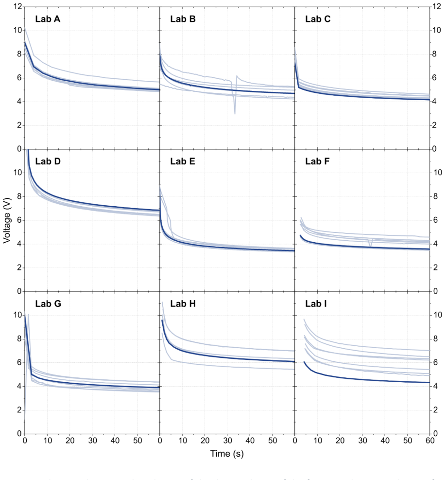
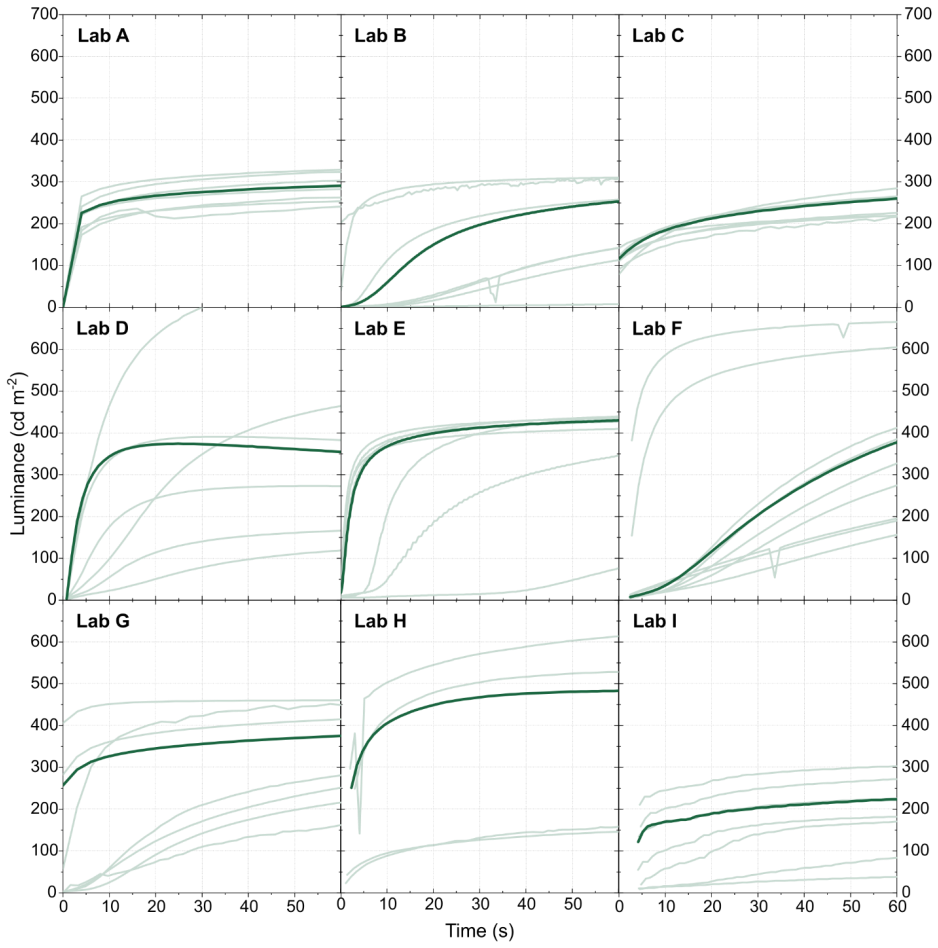
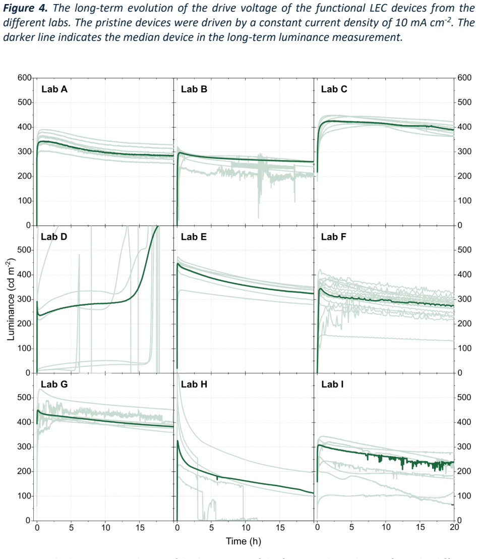
Device characterization IMPORTANT: Only use pristine devices! The LECs must be characterized within 24 h after fabrication either unencapsulated inside a glove box or encapsulated using a cover glass outside the box (please report back). Measure the temporal evolution of the forward luminance and the voltage over > 20 hours using a constant drive current ...
-
[23]
Active-material thickness The thickness of the active material is measured on one of the dried films without a top electrode at three different spots on a pixel area, using, e.g., a profilometer like Bruker Dektak
-
[24]
lifetime
Number of samples Every group prepares and measures at least 8 nominally identical (same person(s) fabricating, all made from the same ink) devices and records at least 8 j-V-L transients as specified above. If the “lifetime” and “turn-on” characteristics cannot be recorded in the same measurement, then at least 8 samples should be measured for each chara...
-
[25]
lab 1, …, lab N
Data evaluation and presentation After receiving the raw data, we will anonymize the group names and label the data sets as “lab 1, …, lab N”. We will present and compare the median of the j-V-L curves of the functional devices (with respect to the peak forward luminance) of the working samples of all labs in one plot, probably one sub-figure per lab. One...
2010
discussion (0)
Sign in with ORCID, Apple, or X to comment. Anyone can read and Pith papers without signing in.