REVIEW 1 major objections 4 minor 12 references
Diffraction and partial coherence make HARMONI spectral lines narrower than the geometric slit, undersampling the detector unless grisms supply anamorphic stretch.
Reviewed by Pith at T0; open to challenge. T0 means a machine referee read the full paper against a public rubric. the ladder, T0–T4 →
T0 review · grok-4.5
2026-07-12 08:17 UTC pith:MNJD73TZ
load-bearing objection Solid instrumentation note that correctly flags HARMONI undersampling from partial coherence and offers a constrained grism fix; physics is old, residual-error budget is the only soft spot. the 1 major comments →
HARMONI at ELT: line spread functions in a diffraction limited spectrometer
The pith
A machine-rendered reading of the paper's core claim, the machinery that carries it, and where it could break.
Core claim
Including diffraction and partial spatial coherence shows that HARMONI’s spectral line-spread function has FWHM less than two detector pixels at all wavelengths in both the 6 mas and 25 mas scales; geometric slit imaging alone therefore produces undersampling that must be corrected by small, band-specific anamorphic factors introduced through the grism sandwich.
What carries the argument
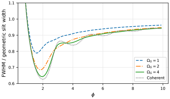
The dimensionless parameters φ = w_s w_G / (λ f_C) and grating oversizing Ω_G, which map any spectrograph onto the family of partially coherent line profiles whose FWHM is read directly from a single curve.
Load-bearing premise
That adding optical aberrations, grating errors, vibration and detector effects in an RSS spreadsheet still yields a reliable as-built FWHM, even though a full Fourier-optics model that folds free-form aberrations together with partial coherence has not yet been finished.
What would settle it
Measure the monochromatic line profiles of the finished HARMONI spectrograph (or a laboratory breadboard with the same slit, grism and free-form optics) across 0.8–2.45 µm and check whether the FWHM values match the post-mitigation curves of Figure 9 rather than the purely geometric two-pixel target.
Editorial analysis
A structured set of objections, weighed in public.
Referee Report
Summary. The paper shows that diffraction and partial spatial coherence at the slit/grating make the HARMONI line-spread function narrower than the geometric slit image. Using Casini and Mielenz expressions re-parameterized by φ = w_s w_G / (λ f_C) and grating oversizing Ω_G, the authors compute FWHM versus wavelength for the 6 mas and 25 mas scales (Figs. 6–8). With geometric imaging sized for two detector pixels, the ideal optical LSF (convolved with the pixel) falls below 2 pixels at all wavelengths, most severely at long λ in the 6 mas scale. They therefore propose grism anamorphic factors (1 ≤ f_j ≤ 1.15) to restore near-Nyquist sampling (Fig. 9) and outline a Fourier-optics path for combining free-form aberrations with partial coherence.
Significance. The work is of clear practical value for ELT/AO integral-field spectrographs and for any diffraction-limited spectrometer. It correctly re-expresses classical laboratory results (Casini, Mielenz) in the dimensionless parameters φ and Ω_G that instrument designers actually control, supplies explicit FWHM curves for HARMONI’s two scales, and documents a concrete, mechanism-free mitigation already compatible with the post-rescope free-form design. The analytic re-parameterization and numerical evaluation of the partial-coherence integral are reproducible from the given equations and HARMONI geometric inputs; the paper therefore supplies both a diagnostic tool and a design guideline that other projects can apply before detailed optical design freezes.
major comments (1)
- Section 4 bases the anamorphic factors f_j on an RSS spreadsheet that folds residual broadening (aberrations, grating errors, vibration, detector) into the ideal FWHM of Fig. 7. Section 5 states that a full end-to-end Fourier-optics model simultaneously including free-form aberrations and partial coherence has not yet been completed. Because the precise values of f_j (and the residual undersampling still visible at long λ in the 6 mas panel of Fig. 9) rest on that incomplete budget, the manuscript should either (a) quantify the uncertainty range on f_j that would still keep sampling within the stated 1–1.15 bounds, or (b) present at least one representative wavelength/scale case from the PROPER+Zemax pipeline to show that the RSS estimate does not reverse the need for, or the direction of, the anamorphic correction.
minor comments (4)
- Eq. (1) and the subsequent definitions of θ±_x, φ and α would benefit from an explicit statement that the grating is assumed rectangular and oversized in the cross-dispersion direction (already implicit in the 1-D treatment).
- Figure 5 caption and text: the shaded α ranges for the two HARMONI scales are useful; adding the corresponding φ or Ω_G values on a second axis would make the link to Fig. 6 immediate.
- Section 3.4: the numerical values w_s = 130 µm, w_G = 50 mm, f_C = 1319 mm are given without a reference to the post-rescope optical design; a short citation or table of the adopted geometric parameters would aid reproducibility.
- A few typographical slips remain (e.g., “ftel fC fL” in the Fig. 2 caption, missing units on some axis labels, and the incomplete sentence “fields of view on the sky of .” in Section 2).
Circularity Check
No circularity: LSF formulas are external literature results applied to fixed HARMONI design parameters; mitigation factors are derived from those predictions, not fitted to observed spectra.
full rationale
The paper's central claim (FWHM < 2 detector pixels from diffraction + partial coherence, Fig. 7) is obtained by numerically evaluating the established analytic line-profile expressions of Casini (coherent/incoherent limits) and Mielenz (partial coherence) after re-parameterizing them in terms of the dimensionless quantities φ = w_s w_G / (λ f_C) and Ω_G (grating oversizing). These formulas are independent of the present work; HARMONI values of slit width, collimator focal length, grating aperture and the two spatial scales are design inputs, not quantities fitted to any LSF data the paper claims to predict. The subsequent grism anamorphic factors (1 ≤ f_j ≤ 1.15) are chosen to restore ~2-pixel sampling given those predicted FWHMs and an RSS residual-error budget; they are not tuned to match already-observed spectra. Self-citations (prior HARMONI modeling papers, the rescope design papers) supply context or describe incomplete future end-to-end Fourier-optics work (Section 5) but do not close any logical loop that forces the undersampling result. The derivation is therefore self-contained against external benchmarks and exhibits no self-definitional, fitted-input-as-prediction, or load-bearing self-citation circularity.
Axiom & Free-Parameter Ledger
free parameters (2)
- anamorphic factor bounds 1 ≤ f_j ≤ 1.15 =
1–1.15
- RSS combination of residual FWHM contributions
axioms (4)
- domain assumption Line profiles for fully coherent and incoherent illumination are given by the sine-integral expressions of Casini (2014).
- domain assumption Average degree of coherence across a slit illuminated by a circular pupil is given by Mielenz’s μ_RMS formula.
- domain assumption A monochromatic extended source can be treated by integrating the coherent point-source response over the entrance pupil with a circular-apodization factor.
- domain assumption Geometric aberrations before the slit plane do not affect the monochromatic LSF of a spatially uniform extended source.
Cite this review
Pith. "Pith review of HARMONI at ELT: line spread functions in a diffraction limited spectrometer." pith.science (2026). https://pith.science/paper/MNJD73TZ
@misc{pith2026260702223,
  author       = {Pith},
  title        = {Pith review of: HARMONI at ELT: line spread functions in a diffraction limited spectrometer},
  year         = {2026},
  howpublished = {\url{https://pith.science/paper/MNJD73TZ}},
  note         = {Machine review of arXiv:2607.02223}
}
read the original abstract
HARMONI is the first light, adaptive optics assisted, near-IR integral field spectrograph for the ELT. It covers a spectral range from 800~nm to 2450~nm with resolving powers from 3000 to 7000 and spatial sampling of 25~mas and 6~mas. It can operate in two adaptive optics modes - SCAO (including a high contrast capability) and MCAO. The project is resuming its final design phase after a rescope design phase in 2025. Diffraction of the pupil becomes significant in a spectrograph where the slit width is comparable to the diffraction limited PSF. When the spatial coherence due to the narrow slit is considered, the resulting line spread function can be narrower than the geometric width of the input slit, with a non-linear dependence on the size of the pupil aperture after the slit. We outline the impact of these diffraction and spatial filtering effects on the line spread function of HARMONI and identify parameters that should be considered when designing a diffraction limited spectrograph.
Figures




Reference graph
Works this paper leans on
-
[1]
On the resolving power of telescopes and spectroscopes for lines of finite width,
Wadsworth, F. L. O., “On the resolving power of telescopes and spectroscopes for lines of finite width,”The London, Edinburgh, and Dublin Philosophical Magazine and Journal of Science43(264), 317–343 (1897). https://doi.org/10.1080/14786449708621001
-
[2]
The enhanced resolution imager and spectrograph for the vlt,
Davies, R., Absil, O., Agapito, G., et al., “The enhanced resolution imager and spectrograph for the vlt,” A&A674, A207 (2023). https://doi.org/10.1051/0004-6361/202346559
-
[3]
Dionne, C. E., Hatch, M., and Overoye, K. R., “Spectral resolution modeling with partial coher- ence for the Atmospheric Infrared Sounder instrument,”Optical Engineering47(2), 026402 (2008). https://doi.org/10.1117/1.2870198
-
[4]
On the instrument profile of slit spectrographs,
Casini, R. and de Wijn, A. G., “On the instrument profile of slit spectrographs,”J. Opt. Soc. Am. A31, 2002–2010 (Sep 2014). https://doi.org/10.1364/JOSAA.31.002002
-
[5]
Spectroscope slit images in partially coherent light,
Mielenz, K. D., “Spectroscope slit images in partially coherent light,”J. Opt. Soc. Am.57, 66–74 (Jan 1967)
1967
-
[6]
HARMONI at ELT: the revitalised high-resolution near-infrared IFU for the ESO ELT,
Dunlop, J., Neichel, B., Chittick, S., et al., “HARMONI at ELT: the revitalised high-resolution near-infrared IFU for the ESO ELT,” in [Ground-based and Airborne Instrumentation for Astronomy XI],Proc. SPIE 14149, SPIE (2026)
2026
-
[7]
HARMONI at ELT: a dynamic systems engineer- ing approach for rescoping the HARMONI integral field spectrograph,
MacIver, A., Garc´ ıa, M. A. C., Ba˜ nares-Palacios, P., et al., “HARMONI at ELT: a dynamic systems engineer- ing approach for rescoping the HARMONI integral field spectrograph,” in [Modeling, Systems Engineering, and Project Management for Astronomy XII],Proc. SPIE14152, SPIE (2026)
2026
-
[8]
HARMONI at ELT: optical design of the spectrograph sub-system,
Muslimov, E. R., Tecza, M., Castillo-Dom´ ınguez, E., et al., “HARMONI at ELT: optical design of the spectrograph sub-system,” in [Ground-based and Airborne Instrumentation for Astronomy XI],Proc. SPIE 14149, SPIE (2026)
2026
-
[9]
MORFEO at ELT: the adaptive optics module for ELT,
Ciliegi, P., Agapito, G., Aliverti, M., et al., “MORFEO at ELT: the adaptive optics module for ELT,” in [Adaptive Optics Systems IX], Jackson, K. J., Schmidt, D., and Vernet, E., eds.,Proc. SPIE13097, 1309722, SPIE (2024). https://doi.org/10.1117/12.3019058
-
[10]
Detector sampling of optical/IR spectra: how many pixels per FWHM?,
Robertson, J. G., “Detector sampling of optical/IR spectra: how many pixels per FWHM?,”Publications of the Astronomical Society of Australia34, e035 (2017)
2017
-
[11]
Todd, S. P., Bond, C. Z., Clarke, F., et al., “HARMONI at ELT: modelling the optical performance of a diffraction limited integral field spectrograph,” in [Modeling, Systems Engineering, and Project Management for Astronomy XI],Proc. SPIE13099, 1309906, SPIE (2024). https://doi.org/10.1117/12.3019747
-
[12]
George, E. M., Gr¨ aff, D., Hartl, M., et al., “Complex spectral line profiles resulting from cryogenic deforma- tion of the SINFONI/SPIFFI diffraction gratings,”Journal of Astronomical Telescopes, Instruments, and Systems3(3), 035002 (2017). https://doi.org/10.1117/1.JATIS.3.3.035002
discussion (0)
Sign in with ORCID, Apple, or X to comment. Anyone can read and Pith papers without signing in.