REVIEW 3 major objections 7 minor 42 references
Separate fibre and matrix fatigue channels, each lowering its own fracture resistance, reproduce orientation- and notch-dependent composite fatigue with one fixed card.
Reviewed by Pith at T0; open to challenge. T0 means a machine referee read the full paper against a public rubric. the ladder, T0–T4 →
T0 review · grok-4.5
2026-07-10 14:21 UTC pith:TG6AAPMJ
load-bearing objection Solid verification of a mode-resolved fatigue extension: real combination novelty, honest scope, and the “tuned card” stress-test is real but already scoped by the paper itself. the 3 major comments →
A Puck-informed mode-resolved phase-field fatigue framework for unidirectional composites
The pith
A machine-rendered reading of the paper's core claim, the machinery that carries it, and where it could break.
Core claim
Resolving fatigue into separate, physically interpretable fibre and matrix/inter-fibre channels—each degrading its own fracture resistance rather than elastic stiffness—is sufficient to reproduce the orientation-, load- and notch-dependent fatigue mechanisms of a unidirectional lamina with one fixed parameter card.
What carries the argument
Mode-resolved fatigue channels: two independent Puck-informed phase fields (fibre and matrix/inter-fibre), each with its own fatigue history, threshold and asymptotic resistance-degradation law that lowers effective fracture energy while leaving elastic stiffness loss to the phase fields themselves.
Load-bearing premise
The structural fatigue numbers (rates, thresholds, exponents and degradation shapes for each channel) are a hand-chosen demonstration card selected for stable channel separation and accessible cycle counts, not an experimentally identified law for the material.
What would settle it
Notched unidirectional coupons of the same material tested under the same cyclic amplitudes and orientations, with full-field or post-mortem mapping of crack sequence: if 0° specimens show early fibre cutting instead of stable matrix splitting that delays fibre failure, or if 45°/90° specimens do not fail by the predicted matrix/inter-fibre modes on the same order of cycles, the sufficiency claim fails.
Editorial analysis
A structured set of objections, weighed in public.
Referee Report
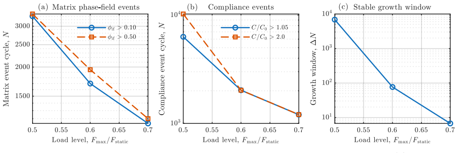
Summary. The manuscript formulates a Puck-informed, two-channel phase-field fatigue model for unidirectional plies in which fibre and matrix/inter-fibre mechanisms each carry independent fatigue histories, thresholds, and resistance-degradation laws. Fatigue lowers channel fracture resistance χ_i rather than elastic stiffness; stiffness loss and crack topology remain controlled by separate phase fields φ_f and φ_if. The model is implemented in Abaqus via a staggered UMAT–UEL architecture and exercised with one fixed IM7/8552 elastic/strength/phase-field card and one fixed fatigue card. One-element tests establish selective channel activation and parameter roles; the same card is then applied without orientation- or geometry-specific retuning to centred-notch and open-hole tension at 0°, 45°, and 90° under monotonic and cyclic loading, plus load-level and hole-size checks. The reported outcomes are mechanism-correct crack modes, the expected life ordering (matrix-dominated failure near 10³ cycles; 0° runout to 2×10⁵ with stable longitudinal splitting and inactive fibre field), and field-extracted evidence of split-induced fibre-channel shielding. The work is explicitly framed as numerical verification and cross-geometry consistency, not experimental life prediction.
Significance. If the formulation holds as a verified computational framework, it closes a clear gap between Puck-informed multi-phase-field fracture (previously largely monotonic) and recent composite phase-field fatigue models that do not assign independent fatigue histories to fibre versus inter-fibre channels. The separation of fatigue accumulation from stiffness loss is physically interpretable and makes the 0° split-induced shielding mechanism observable rather than conflated into a single damage variable. Strengths that should be credited include: a transparent verification-first programme (one-element channel separation, parameter-role sweeps, optional mean-stress check); a single fixed card applied across two independent notched geometries and three orientations; mesh/length-scale and cycle-block convergence documentation; and quantitative near-notch field extraction (Supplementary Table S1) supporting the shielding interpretation. Within the stated non-calibrated scope, this is a solid contribution to computational composite fatigue modelling and a usable basis for later experimental identification.
major comments (3)
- The one-sentence claim (Introduction) that mode-resolved resistance-only fatigue is “sufficient” to reproduce orientation-, load-, and notch-dependent mechanisms with one fixed card is demonstrated only for a post-selected demonstration set. Section 4.2 states that Table 2 values “were selected after the one-element verification and sensitivity studies to produce stable channel separation, matrix/inter-fibre fatigue evolution on an accessible cycle scale, and a subcritical fibre channel.” That selection is disclosed, but the structural campaign does not probe whether a different yet still channel-separating card preserves mode purity and life ordering. Because the quasi-static Puck latch, anisotropic projectors A_i, and the large G_c,f/G_c,if disparity already bias topology, the fatigue extension’s contribution to “sufficiency” needs either (i) a short robustness check (e.g. modest pertu
- Relatedly, the manuscript should more sharply isolate what the fatigue extension adds beyond the underlying quasi-static two-phase-field Puck model. Static CNT/OHT results (Tables 7 and 9, Figs. 3 and 5) already recover transverse, off-axis, and longitudinal-split topologies; the fatigue results mainly show that, under the chosen amplitudes and Table 2 thresholds/rates, the fibre channel stays subcritical at 0° while matrix channels fail at 45°/90°. Section 9.1’s shielding argument is the right place to make this isolation quantitative: state which outcomes (runout, inactive φ_f, reduced P99(σ_⊥) and P99(τ_12) with finite P99(σ_∥)) cannot be obtained from the quasi-static model alone or from a single-channel fatigue degradation of a shared G_c. A brief single-channel or χ_f≡χ_if control comparison on one 0° fatigue case would make the mode-resolved fatigue contribution load-bearing rathe
- Fatigue amplitude selection is case-specific and affects the reported lives, yet is only lightly justified. OHT fatigue uses U_max equal to 70% of the static displacement at which φ_if first exceeds 0.10 (Section 8.2); CNT uses separately chosen U_max values (Table 8). The fixed material/fatigue card is not retuned, but the driving levels are. For a verification claim of cross-geometry consistency of mechanisms this is acceptable; for any reading of life ordering as more than qualitative, the paper should state that absolute N_f values are amplitude-protocol dependent and report, at least for one matrix-dominated case, sensitivity of N_f to the 70% choice (e.g. 60% and 80%), analogous to the existing load-controlled OHT90 amplitude study (Table 11). Without that, Tables 8 and 10 should be labelled more clearly as protocol-dependent mechanism benchmarks rather than transferable life numbe
minor comments (7)
- Section 1, organization paragraph: “Section 2 the mode-resolved phase-field formulation” is missing a verb (“presents” / “introduces”).
- Section 2.1: the θ versus paper orientation α convention (0° implemented as θ=90°, etc.) is easy to misread later; a one-line table or repeated reminder in figure captions for CNT/OHT would help.
- Equations (11)–(13): the floor on F_raw_i,min and the cap bF_max are numerical safeguards; state briefly that all structural R=0.1 results are insensitive to the floor (or give the values used for ε and bF_max).
- Table 4 and Section 4.4: OHT mesh sensitivity is reported for static load level only; a one-sentence note that fatigue crack mode (not only static peak) was unchanged between h=0.25 and 0.20 mm would complete the convergence story.
- Figures 4 and 6: stage labels (“Stage 1/2/3”) are clear, but absolute cycle numbers on each panel would make the ~10³ versus 2×10⁵ contrast readable without returning to the tables.
- Section 9.6 / Conclusions: the path to experimental validation is well stated; adding 1–2 concrete observables (e.g. split length vs N in 0° OHT, compliance growth rate vs D in 90°) would make the validation roadmap more actionable.
- References: ensure consistent journal styling and DOI formatting; a few entries (e.g. recent 2025–2026 items) should be double-checked for final bibliographic details at production.
Circularity Check
Mild fitted-input circularity: the fatigue card was post-selected after one-element studies to produce the target hierarchy, then frozen; cross-geometry consistency is real but only for that demonstration set.
specific steps
-
fitted input called prediction
[§4.2 (IM7/8552 material and fatigue parameters); Table 2; one-sentence claim in §1]
"They were selected after the one-element verification and sensitivity studies to produce stable channel separation, matrix/inter-fibre fatigue evolution on an accessible cycle scale, and a subcritical fibre channel under the selected fibre-aligned fatigue amplitudes. Once selected, the same card is held fixed for all CNT, OHT, load-level, and hole-size studies; no parameter is re-tuned by orientation, geometry, or load case."
The free fatigue parameters (C_fat, p_fat, F_th, κ_T, a per channel) were hand-chosen after one-element tests expressly so that matrix/inter-fibre fatigue evolves on a short cycle scale while the fibre channel stays subcritical under fibre-aligned amplitudes. The structural “reproduction” of the expected hierarchy (45°/90° collapse ~10³ cycles by inter-fibre cracking; 0° run-out to 2×10⁵ with max ϕ_f = 0) is therefore achieved for a card already tuned to that hierarchy. The claim that separate channels “suffice” with one fixed card is thus shown only for a post-selected demonstration set, not for an a-priori or experimentally identified card. The paper is transparent about this, so the circularity is mild rather than hidden.
full rationale
The paper is a transparent numerical-verification study, not a first-principles life prediction, and it repeatedly disclaims experimental calibration. The formulation itself (two Puck channels, resistance degradation χ_i(κ̄_i) rather than direct stiffness loss, anisotropic projectors A_i, staggered UMAT–UEL) is a modeling construction, not a circular derivation. Cross-geometry transfer (CNT vs OHT), load-level trends, and hole-size trends without retuning are independent content and are not forced by the one-element selection alone. The only circularity is mild and of the fitted-input kind: Table 2 free parameters were chosen after D1/D2 specifically to yield stable channel separation, accessible matrix lives, and a subcritical fibre channel under the chosen 0° amplitudes; the one-sentence “sufficiency with one fixed card” claim is therefore demonstrated only for a card already tuned to that qualitative hierarchy. Self-citations of the author’s prior monotonic multi-phase-field work are normal lineage, not load-bearing uniqueness theorems. Score 3 reflects that single soft circular step without elevating an honest verification paper into a forced tautology.
Axiom & Free-Parameter Ledger
free parameters (8)
- C_fat,f / C_fat,if (channel accumulation coefficients)
- p_fat,f / p_fat,if (fatigue exponents)
- F_th,f / F_th,if (fatigue thresholds)
- κ_T,i and a_i (resistance transition and shape)
- ℓ_f, ℓ_if, G_c,f, G_c,if (phase-field lengths and toughnesses)
- Puck p-parameters and strength set (R1T, R2T, R12, …)
- β_mean,i (mean-stress coefficients)
- Fatigue amplitude selection (e.g. 70% of static ϕ_if onset displacement)
axioms (6)
- domain assumption AT2 phase-field regularization with channel-wise anisotropic structural tensors A_f, A_if correctly represents fibre-break vs longitudinal-split topologies.
- domain assumption Puck efforts distinguish fibre vs inter-fibre activation and remain valid drivers under cyclic proportional min/max evaluation with the stated min-effort floor.
- ad hoc to paper Fatigue acts only by degrading channel fracture resistance χ_i; it never directly degrades elastic stiffness.
- domain assumption Homogenized elastic orthotropic ply under plane stress with component-wise energy split (ψ11, ψ22, ψ12) and g_mix shear coupling is sufficient for notched UD fatigue mechanisms studied.
- standard math Staggered UMAT–UEL solve with irreversibility penalties and fixed cycle blocks converges to mesh/length-scale-controlled paths within reported 2–4% life variation.
- ad hoc to paper Raw reaction spikes without smooth structural response or stable phase-field pattern may be discarded as numerical.
invented entities (3)
-
Mode-resolved fatigue channels (fibre vs matrix/inter-fibre) with independent κ̄_i, F_th,i, χ_i
no independent evidence
-
Resistance-only fatigue degradation law χ_i(κ̄_i) with transition κ_T,i and shape a_i
no independent evidence
-
Split-induced fibre-channel shielding as a model-level mechanism
no independent evidence
read the original abstract
Fatigue fracture in unidirectional fibre-reinforced composites is strongly mode dependent: transverse and off-axis cycling is governed by matrix and inter-fibre mechanisms, whereas fibre-aligned cycling activates a longitudinal channel with a higher fracture-energy scale and a different crack topology. Single-damage-variable models can fit global stiffness loss but cannot identify the active mechanism. This work proposes a Puck-informed, mode-resolved phase-field fatigue framework with separate channels for fibre-dominated and matrix/inter-fibre fatigue. Each channel has its own fatigue history, threshold, and resistance-degradation law. Fatigue does not directly degrade elastic stiffness; it lowers the fracture resistance of the active channel, while the corresponding phase field controls stiffness loss and crack-path evolution. The formulation is implemented in Abaqus/Standard using a compact UMAT-UEL architecture with one orthotropic mechanical routine and two scalar phase-field layers. Using one fixed IM7/8552 material and fatigue card, the model is verified through one-element tests, parameter sweeps, and centred-notch and open-hole tension cases at 0, 45, and 90 degrees under monotonic and cyclic loading. Without orientation- or geometry-specific tuning, the framework reproduces transverse matrix/inter-fibre cracking at 90 degrees, off-axis cracking at 45 degrees, and longitudinal matrix splitting with delayed fibre activation at 0 degrees. The fatigue lives follow the expected ordering: 45- and 90-degree cases fail within about 1,000 cycles, while 0-degree cases run out to 200,000 cycles without fibre cracking. Additional load, hole-size, mesh, length-scale, and cycle-block studies confirm consistent crack modes and converged trends. The study is a numerical verification and cross-geometry consistency assessment, not a calibrated experimental life-prediction claim.
Figures



Reference graph
Works this paper leans on
-
[1]
R. Talreja, Fatigue of composite materials: damage mechanisms and fatigue-life dia- grams, Proceedings of the Royal Society A: Mathematical, Physical and Engineering Sciences 378 (1981) 461–475. doi:10.1098/rspa.1981.0163
-
[2]
E.K. Gamstedt, R. Talreja, Fatigue damage mechanisms in unidirectional carbon- fibre-reinforced plastics, Journal of Materials Science 34 (1999) 2535–2546. doi:10.1023/A:1004684228765
-
[3]
K.L. Reifsnider, R. Jamison, Fracture of fatigue-loaded composite laminates, Interna- tional Journal of Fatigue 4 (1982) 187–197. doi:10.1016/0142-1123(82)90001-9
-
[4]
J. Degrieck, W. Van Paepegem, Fatigue damage modeling of fibre-reinforced composite materials: Review, Applied Mechanics Reviews 54 (2001) 279–300. doi:10.1115/1.1381395
-
[5]
P. Alam, D. Mamalis, C. Robert, C. Floreani, C.M. Ó Brádaigh, The fatigue of carbon fibre reinforced plastics – A review, Composites Part B: Engineering 166 (2019) 555–579. doi:10.1016/j.compositesb.2019.02.016
-
[6]
M. Quaresimin, L. Susmel, R. Talreja, Fatigue behaviour and life assessment of com- posite laminates under multiaxial loadings, International Journal of Fatigue 32 (2010) 2–16. doi:10.1016/j.ijfatigue.2009.02.012
-
[7]
P.A. Carraro, M. Quaresimin, A damage based model for crack initiation in unidirec- tional composites under multiaxial cyclic loading, Composites Science and Technology 99 (2014) 154–163. doi:10.1016/j.compscitech.2014.05.012. 35
-
[8]
O.J. Nixon-Pearson, S.R. Hallett, P.J. Withers, J. Rouse, Damage development in open- hole composite specimens in fatigue. Part 1: Experimental investigation, Composite Structures 106 (2013) 882–889. doi:10.1016/j.compstruct.2013.05.033
-
[9]
O.J. Nixon-Pearson, S.R. Hallett, An investigation into the damage development and residualstrengthsofopen-holespecimensinfatigue, CompositesPartA:AppliedScience and Manufacturing 69 (2015) 266–278. doi:10.1016/j.compositesa.2014.11.013
-
[10]
P. Hofman, F.P. van der Meer, L.J. Sluys, Modeling of progressive high-cycle fatigue in composite laminates accounting for local stress ratios, Composites Part A: Applied Science and Manufacturing 183 (2024) 108219. doi:10.1016/j.compositesa.2024.108219
-
[11]
G.A. Francfort, J.-J. Marigo, Revisiting brittle fracture as an energy minimiza- tion problem, Journal of the Mechanics and Physics of Solids 46 (1998) 1319–1342. doi:10.1016/S0022-5096(98)00034-9
-
[12]
B. Bourdin, G.A. Francfort, J.-J. Marigo, Numerical experiments in revisited brit- tle fracture, Journal of the Mechanics and Physics of Solids 48 (2000) 797–826. doi:10.1016/S0022-5096(99)00028-9
-
[13]
C. Miehe, M. Hofacker, F. Welschinger, A phase field model for rate-independent crack propagation: robust algorithmic implementation based on operator splits, Computer Methods in Applied Mechanics and Engineering 199 (2010) 2765–2778. doi:10.1016/j.cma.2010.04.011
-
[14]
R. Alessi, S. Vidoli, L. De Lorenzis, A phenomenological approach to fatigue with a variational phase-field model, Engineering Fracture Mechanics 190 (2018) 53–73. doi:10.1016/j.engfracmech.2017.11.036
-
[15]
A. Mesgarnejad, A. Imanian, A. Karma, Phase-field models for fatigue crack growth, Theoretical and Applied Fracture Mechanics 103 (2019) 102282. doi:10.1016/j.tafmec.2019.102282
-
[16]
Y.-S. Lo, M.J. Borden, K. Ravi-Chandar, C.M. Landis, A phase-field model for fa- tigue crack growth, Journal of the Mechanics and Physics of Solids 132 (2019) 103684. doi:10.1016/j.jmps.2019.103684
-
[17]
P. Carrara, M. Ambati, R. Alessi, L. De Lorenzis, A framework to model the fatigue behaviour of brittle materials based on a variational phase-field approach, Computer Methods in Applied Mechanics and Engineering 361 (2020) 112731. doi:10.1016/j.cma.2019.112731
-
[18]
M. Seiler, T. Linse, P. Hantschke, M. Kästner, An efficient phase-field model for fa- tigue fracture in ductile materials, Engineering Fracture Mechanics 224 (2020) 106807. doi:10.1016/j.engfracmech.2019.106807
-
[19]
Z. Khalil, A.Y. Elghazouli, E. Martínez-Pañeda, A generalised phase field model for fatigue crack growth in elastic–plastic solids with an efficient monolithic solver, 36 Computer Methods in Applied Mechanics and Engineering 388 (2022) 114286. doi:10.1016/j.cma.2021.114286
-
[20]
A. Dean, M. Hematipour, P.K. Asur Vijaya Kumar, R. Rolfes, Experimental– numerical phase-field modelling of ductile and fatigue fracture in short fibre- reinforced polymeric adhesives, Composites Science and Technology 279 (2026) 111588. doi:10.1016/j.compscitech.2026.111588
-
[21]
T.Q. Bui, X. Hu, A review of phase-field models, fundamentals and their appli- cations to composite laminates, Engineering Fracture Mechanics 248 (2021) 107705. doi:10.1016/j.engfracmech.2021.107705
-
[22]
M. Kalina, T. Schneider, J. Brummund, M. Kästner, Overview of phase-field models for fatigue fracture in a unified framework, Engineering Fracture Mechanics 288 (2023) 109318. doi:10.1016/j.engfracmech.2023.109318
-
[23]
A. Quintanas-Corominas, J. Reinoso, E. Casoni, A. Turon, J.A. Mayugo, A phase field approach to simulate intralaminar and translaminar fracture in long fiber composite materials, Composite Structures 220 (2019) 899–911. doi:10.1016/j.compstruct.2019.02.007
-
[24]
W. Tan, E. Martínez-Pañeda, Phase field predictions of microscopic fracture and R- curve behaviour of fibre-reinforced composites, Composites Science and Technology 202 (2021) 108539. doi:10.1016/j.compscitech.2020.108539
-
[25]
W. Tan, E. Martínez-Pañeda, Phase field fracture predictions of microscopic bridg- ing behaviour of composite materials, Composite Structures 286 (2022) 115242. doi:10.1016/j.compstruct.2022.115242
-
[26]
A. Dean, P.K. Asur Vijaya Kumar, J. Reinoso, C. Gerendt, M. Paggi, E. Mahdi, R. Rolfes, A multi phase-field fracture model for long fiber reinforced compos- ites based on the Puck theory of failure, Composite Structures 251 (2020) 112446. doi:10.1016/j.compstruct.2020.112446
-
[27]
P.K. Asur Vijaya Kumar, A. Dean, J. Reinoso, M. Paggi, A multi phase-field-cohesive zone model for laminated composites: Application to delamination migration, Compos- ite Structures 276 (2021) 114471. doi:10.1016/j.compstruct.2021.114471
-
[28]
P.K. Asur Vijaya Kumar, R. Fleischhacker, A. Dean, R. Rolfes, H.E. Pettermann, Re- visiting multi-phase field model for FRCs using Puck theory, Composite Structures 372 (2025) 119549. doi:10.1016/j.compstruct.2025.119549
-
[29]
P. Zhang, S. Tan, X. Hu, W. Yao, X. Zhuang, A double-phase field model for multiple failures in composites, Composite Structures 293 (2022) 115730. doi:10.1016/j.compstruct.2022.115730
-
[30]
X. Li, C. Zhou, C. Xing, A. He, J. Yu, G. Wang, A phase-field fracture model for fatigue behavior in fiber-reinforced composites, International Journal of Mechanical Sciences 269 (2024) 108989. doi:10.1016/j.ijmecsci.2024.108989. 37
-
[31]
H. Sharma, A. Singh, A degradation-informed phase-field model for matrix-dominated high-cycle fatigue in 3D composite laminates, Composites Part A: Applied Science and Manufacturing 201 (2026) 109377. doi:10.1016/j.compositesa.2025.109377
-
[32]
J.M. Wolla, J.G. Goree, Experimental evaluation of longitudinal splitting in unidirectional composites, Journal of Composite Materials 21 (1987) 49–67. doi:10.1177/002199838702100104
-
[33]
S.L. Bazhenov, Longitudinal splitting in unidirectional fibre-reinforced composites with an open hole, Composites Science and Technology 58 (1998) 83–89. doi:10.1016/S0266- 3538(97)00097-3
-
[34]
G. Liu, K. Tang, Study on stress concentration in notched cross-ply lami- nates under tensile loading, Journal of Composite Materials 50 (2016) 283–296. doi:10.1177/0021998315573802
-
[35]
A. Puck, H. Schuermann, Failure analysis of FRP laminates by means of physically based phenomenological models, Composites Science and Technology 58 (1998) 1045–
work page 1998
-
[36]
doi:10.1016/S0266-3538(96)00140-6
-
[37]
A. Puck, H. Schuermann, Failure analysis of FRP laminates by means of physically based phenomenological models, Composites Science and Technology 62 (2002) 1633–
work page 2002
-
[38]
doi:10.1016/S0266-3538(01)00208-1
-
[39]
Z. Hashin, Failure criteria for unidirectional fiber composites, Journal of Applied Me- chanics 47 (1980) 329–334. doi:10.1115/1.3153664
-
[40]
K. Marlett, Hexcel 8552 IM7 Unidirectional Prepreg 190 gsm & 35%RC Qualification Material Property Data Report, NCAMP Test Report CAM-RP-2009-015 Rev. A, Na- tional Institute for Aviation Research, Wichita State University, 2011
work page 2009
-
[41]
C.M. Arndt, N.V. de Carvalho, M.W. Czabaj, Experimental reexamination of transverse tensile strength for IM7/8552 tape-laminate composites, Journal of Composite Materials 54 (2020) 3297–3312. doi:10.1177/0021998320914065
-
[42]
H. Koerber, J. Xavier, P.P. Camanho, High strain rate characterisation of uni- directional carbon-epoxy IM7-8552 in transverse compression and in-plane shear using digital image correlation, Mechanics of Materials 42 (2010) 1004–1019. doi:10.1016/j.mechmat.2010.09.003. 38
discussion (0)
Sign in with ORCID, Apple, or X to comment. Anyone can read and Pith papers without signing in.