REVIEW 3 major objections 6 minor 57 references
Capturing the calendering U-shape in lithium-ion electrode thermal conductivity
T0 review · 3 major / 6 minor · reviewed 2026-07-14 · grok-4.5
Pith's one-line read A compression-indexed contact term on a Knudsen-corrected Zehner–Bauer–Schlünder base reproduces the measured U-shaped through-plane thermal conductivity of calendered lithium-ion electrodes.
desk verdict Solid, honest ZBS extension that finally captures the calendering U-shape with a process-indexed contact term; the fit is real but the coefficients and anode mechanism remain under-determined until texture/SEM arrive. read the letter →
The pith
A machine-rendered reading of the paper's core claim, the machinery that carries it, and where it could break.
The reading
What carries the argument
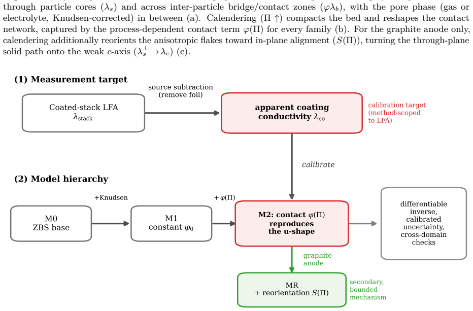
The compression-indexed bridge fraction φ(Π) = max(0, φ₀ + aΠ + bΠ²) multiplying a solid-bridge channel inside the flattened-contact Zehner–Bauer–Schlünder unit cell, always with the Smoluchowski/Knudsen correction on the pore gas; for graphite an optional Hermans orientation factor S(Π) that rotates the anisotropic solid conductivity toward the c-axis floor.
What would settle it
Same-sheet XRD (002) texture and ion-milled SEM contact-area measurements on the calendered graphite sheets: if the Hermans factor does not rise and saturate near the conductivity minimum while NMC shows no conduction-relevant texture change, reorientation is ruled out and the anode minimum collapses to a contact-only account with an unexplained low solid conductivity.
Extended reading notes
Core claim
The central claim is that a low-dimensional, calendering-aware contact term φ(Π) on a Knudsen-corrected Zehner–Bauer–Schlünder base is sufficient to reproduce the through-plane conductivity U-shape that porosity-only and static-contact closures miss. For NMC cathodes the dip is contact-network shear then interlocking; for graphite anodes the same contact term works, and a bounded flake-reorientation account also fits and explains the low through-plane solid conductivity by driving heat across the weak c-axis. The calibrated quantity is the LFA-derived apparent coating conductivity after foil subtraction, and parameters are reported as grouped bridge conductances and likelihood valleys rather
Load-bearing premise
That a three-coefficient quadratic contact law fitted separately to only six-to-eight calendering states per electrode family is capturing real damage-and-recovery physics rather than residual curve flexibility, even though solid conductivity and as-coated bridge fraction remain partially confounded.
Signed reviews
Editorial analysis
A structured set of objections, weighed in public.
Referee Report
Summary. The manuscript proposes a calendering-aware extension of the Knudsen-corrected Zehner–Bauer–Schlünder (ZBS) closure for the through-plane effective thermal conductivity of lithium-ion electrode coatings. A compression-indexed contact fraction φ(Π)=max(0, φ0+aΠ+bΠ²) is added to a ZBS base so that the model can reproduce the measured non-monotonic (U-shaped) dependence of λ_eff on calendering across four electrode families (thin/thick graphite anodes and NMC622/NMC811 cathodes; 27 states). Ablation shows MAPE falling from 31.1% (zero-fit M0) to 13.5% (constant contact M1) to 4.5% (process-dependent M2), with leave-one-state-out error 7.8%. For graphite, a secondary reorientation model MR that couples a Hermans factor S(Π) into anisotropic solid conductivity is shown to fit comparably with one fewer parameter, while remaining degenerate with contact-only fits on conductivity data alone; for isotropic NMC, reorientation is inert and contact evolution is required. The authors carefully scope absolute parameters to an LFA-derived, source-subtracted coating target, report grouped bridge conductance and profile-likelihood valleys rather than over-interpreted point estimates, and supply open code, inverse feasibility checks, and a mechanism-discriminating experimental campaign.
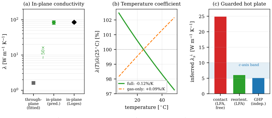
Significance. If the primary claim holds, the paper supplies the first low-dimensional analytical closure in the tested hierarchy that captures the calendering U-shape rather than a monotonic rise, which matters for process-aware battery thermal models and for treating λ_eff as a process-dependent input rather than a handbook constant. Strengths that raise the contribution above a pure curve fit include: the explicit ablation hierarchy and held-out LOSO; honest method-scoping (LFA vs GHP scale shift 1.8–2.4×); profile-likelihood and Bayesian identifiability analysis that correctly demotes λ_s and φ0 to a valley and elevates the bridge product G0; the cathode inertness test that cleanly requires contact evolution; orthogonal consistency checks (in-plane conductivity via trace conservation, temperature-coefficient sign, XRD texture trend); and a fully open, differentiable JAX implementation with inverse and falsifiable campaign design. These make the work useful even if the quadratic coefficients themselves are not uniquely physical.
major comments (3)
- §3.4, Eq. (7) and §5.3/Table 3: The central claim that process-dependent microstructural evolution is necessary is supported by the ablation (M0/M1 cannot produce the dip; M2 does). However, with four free parameters on only 6–8 states per family, the sign-constrained quadratic φ(Π) is still the lowest-order form that can absorb a dip-then-recovery residual. The manuscript already shows low-order polynomials tie on LOSO and that a free spline is unstable (§5.6). The load-bearing claim should be tightened in the abstract/conclusion to “a process-dependent contact term is necessary within the tested hierarchy,” with the specific (a,b) coefficients and G0 values presented as grouped, family-scoped descriptors rather than uniquely identified contact physics, unless the adhesion/SEM campaign of §7 is completed.
- §5.4, Table 4 and Eqs. (8)–(9): For graphite, MR and M2 fit equally well (1.8–1.9% thin; 5.2–5.4% thick), and the authors correctly call this a structural degeneracy. The abstract and primary-claim language still present reorientation as the graphite mechanism that “initially reduces favourable through-plane pathways.” That should be demoted consistently to the secondary, bounded claim already stated in the claim-scope paragraph, with the unique identification deferred to same-sheet XRD texture. Leaving the abstract stronger than the body overstates what conductivity data alone establish.
- §4.1 and §5.9 / inverse_realdata: The inverse porosity QC is demonstrated at ±0.008 RMSE on synthetic 3%-noise data, but on the real Gandert sheets under a held-out protocol the RMSE is ~0.05 (only 44% of sheets inside ±0.02). The abstract and §5.9 framing still lean on the synthetic figure for “quality control.” Either the real-data inverse performance should be the headline number, or the inverse should be clearly labelled a numerical feasibility study pending the metrology campaign, so that the primary thermal-closure claim is not diluted by an overstated application.
minor comments (6)
- Fig. 5 error bars are the reconstruction uncertainty (~5%); state explicitly in the caption that they are not the primary measurement scatter alone, to avoid conflating the four error quantities defined at the start of §5.
- Table 1 and Table 3: mark bound-active λ_s values more prominently (already noted with †) and consider moving the full (λ_s, φ0, a, b) tuples to SI, keeping only G0 and sign(a) in the main table to reinforce the grouped-quantity message.
- Notation: Π is introduced as compression rate in Eq. (1) but sometimes read as a pressure-like variable; a one-line reminder that Π = 1 − s_co/s_co,0 (thickness-based) would help non-specialist readers.
- §5.2 / separator discussion: the compensatory continuum sphere-pack agreement is a useful diagnostic; a short sentence cross-referencing the two-pressure experiment of §7 would tighten the falsifiability link.
- References and arXiv date (10.07.2026 / v1 13 Jul 2026) look future-dated relative to typical review timelines; confirm versioning and any dual-submission status for the record.
- Minor typography: “calendering U-shape” vs “u-shape” is inconsistent in title/abstract/body; pick one capitalization convention.
Circularity Check
Mild fitted-form circularity on the U-shape: the quadratic φ(Π) is chosen as the lowest-order dip-capable ansatz and fitted to the same series; necessity via ablation remains independent content.
-
fitted input called prediction
[Sec. 3.4 Eq. (7); Sec. 5.3 ablation / Fig. 5]
"The lowest-order polynomial able to express a dip followed by a recovery is a quadratic, so we set φ(Π)=max(0,φ0+aΠ+bΠ²)… Making the contact fraction process-dependent (M2, Eq.(7)) reaches 4.5%… and reproduces the u-shape (Fig. 5), where the dip reflects early bridge damage (a<0 in all four families)"
The functional form is chosen specifically because it can produce a non-monotonic dip-then-recovery; a is free to be negative and b free to recover. Fitting (φ0,a,b) to the same 6–8 calendering states that exhibit the U-shape then reporting that M2 “reproduces the u-shape” is largely by construction of ansatz capacity. M0/M1 failure still shows process dependence is needed, but the existence of the dip under M2 is not an independent prediction—it is the fit of a dip-capable form to dip-containing data.
-
fitted input called prediction
[Sec. 5.9 Inverse feasibility; Fig. 8]
"On a synthetic production batch of 200 calendered sheets (true porosities drawn from N(0.30,0.012)… with 3% relative measurement noise), Newton inversion (Eq.(10)) recovers porosity with a root-mean-square error of 0.0078 absolute and zero bias"
Synthetic porosities are inverted through the same closure that generates λeff(ε); recovery to ±0.008 is a self-consistency / numerical feasibility check, not an external prediction. The paper labels it a feasibility study and reports coarser ~0.05 RMSE on real held-out sheets, so the circularity is minor and disclosed rather than load-bearing for the primary claim.
full rationale
The paper does not claim a zero-shot first-principles derivation of the calendering U-shape from independent contact-area or texture data. Its primary result is a calibrated hierarchy: Knudsen-corrected ZBS (M0) and constant-contact (M1) cannot produce the measured non-monotonicity, while a sign-constrained quadratic φ(Π) fitted per family does, cutting MAPE 31.1%→4.5%. That necessity argument is not circular—it is an ablation against nested baselines on the same target. The soft circularity is narrower: Sec. 3.4 explicitly selects the quadratic as the lowest-order polynomial able to express damage-then-recovery, then Sec. 5.3 reports that the fitted form “reproduces the u-shape.” With a free to be negative and b free to recover, non-monotonicity is capacity of the ansatz, not an independent prediction of the dip’s existence. The paper largely owns this (phenomenological, not derived; grouped G0; structural degeneracy of MR vs M2; method-scoped LFA scale), so the central claim still has independent content. No self-citation load-bearing chain, uniqueness theorem, or renaming of a known result was found. Orthogonal checks (in-plane via trace conservation, temperature-coefficient sign, external XRD trend overlays) are not forced by the through-plane fit. Score 3 reflects one clear fitted-input-as-reproduction step without collapse of the necessity claim.
Assumptions & free parameters
free parameters (7)
- λs (through-plane solid conductivity per family)
- φ0 (as-coated bridge area fraction)
- a (shear-damage rate in φ(Π))
- b (interlocking recovery in φ(Π))
- S0, s (Hermans as-coated factor and alignment rate, MR)
- β (gas–surface jump coefficient)
- λa, λc, λb (constituent conductivities)
assumptions (7)
- domain assumption Zehner–Bauer–Schlünder packed-bed unit cell (fluid channel + particle-core channel with deformation parameter B) is the correct morphology for low-additive electrodes.
- domain assumption Smoluchowski/Knudsen correction λg,eff=λg/(1+2β Kn) with single hydraulic pore size applies to dry electrode pores under helium purge.
- ad hoc to paper Calendering contact evolution is representable by the lowest-order quadratic φ(Π)=max(0,φ0+aΠ+bΠ²) with a<0, b≥0.
- domain assumption Steady diffusive conduction only; radiation and pore convection negligible at ambient coating scale (A1).
- domain assumption A single lumped bridge fraction φ absorbs intra-coating bridges and residual coating–collector interface left by foil subtraction (A4).
- ad hoc to paper Graphite through-plane solid conductivity follows Hermans orientation: λ⊥s(S)=(1−S)(2λa+λc)/3 + S λc with S=clip(S0+sΠ,0,1).
- domain assumption Calibration target is LFA-derived apparent coating conductivity after series foil subtraction under helium.
invented entities (2)
-
Compression-indexed contact fraction φ(Π) (quadratic damage–recovery law)
-
Calendering-driven Hermans factor S(Π) coupled into anisotropic solid conductivity for graphite
Cite this review
Pith. "Pith review of Capturing the calendering U-shape in lithium-ion electrode thermal conductivity." pith.science (2026). https://pith.science/paper/DGKDJ7W2
@misc{pith2026260711521,
  author       = {Pith},
  title        = {Pith review of: Capturing the calendering U-shape in lithium-ion electrode thermal conductivity},
  year         = {2026},
  howpublished = {\url{https://pith.science/paper/DGKDJ7W2}},
  note         = {Machine review of arXiv:2607.11521}
}
read the original abstract
Calendering is a key manufacturing step in lithium-ion electrode production, increasing volumetric energy density by reducing electrode porosity. Its effect on through-plane effective thermal conductivity, however, can be non-monotonic: measurements of graphite-based anodes show an initial decrease in thermal conductivity during early calendering followed by recovery at higher compaction. Conventional porosity-based effective-medium closures cannot reproduce this U-shaped behaviour. We develop a calendering-aware extension of the Zehner--Bauer--Schl\"under model that combines a Knudsen-corrected porous-medium baseline with a compression-indexed contact contribution. For graphite electrodes, the model represents the competing effects of increasing particle contact and calendering-induced reorientation of anisotropic graphite particles, which initially reduces favourable through-plane heat-transport pathways. For quasi-isotropic NMC cathodes, the observed response is instead captured through process-dependent contact-network evolution. Across 27 calendering states spanning thin and thick graphite anodes and NMC622 and NMC811 cathodes, the proposed closure reduces the mean absolute percentage error from 31.1% for the zero-fit reference model to 4.5%. The result shows that incorporating process-dependent microstructural evolution is necessary to capture the measured conductivity minimum. Validation across additional electrode formulations, thicknesses, and chemistries remains necessary to assess transferability.
Figures


Figures from the paper (8 more)



Reference graph
Works this paper leans on
-
[1]
T. M. Bandhauer, S. Garimella, T. F. Fuller, A critical review of thermal issues in lithium-ion batteries,J. Electrochem. Soc.158(2011) R1–R25
2011
-
[2]
Richter, S
F. Richter, S. Kjelstrup, P. J. S. Vie, O. S. Burheim, Thermal conductivity and internal temperature profiles of Li-ion secondary batteries,J. Power Sources359(2017) 592–600
2017
-
[3]
Steinhardt et al., Low-effort determination of heat capacity and thermal conductivity for cylindrical 18650 and 21700 lithium-ion cells,J
M. Steinhardt et al., Low-effort determination of heat capacity and thermal conductivity for cylindrical 18650 and 21700 lithium-ion cells,J. Energy Storage42(2021) 103065
2021
-
[4]
D.Oehler,Bestimmung der thermischen Transporteigenschaften poröser Elektroden von Lithium-Ionen Batterien, Dissertation, KIT Scientific Publishing, Karlsruhe, 2021. DOI 10.5445/KSP/1000136047
-
[5]
Steinhardt, J
M. Steinhardt, J. V. Barreras, H. Ruan, B. Wu, G. J. Offer, A. Jossen, Meta-analysis of experimental results for heat capacity and thermal conductivity in lithium-ion batteries: A critical review,J. Power Sources522 (2022) 230829
2022
-
[6]
Steinhardt, E
M. Steinhardt, E. I. Gillich, M. Stiegler, A. Jossen, Thermal conductivity inside prismatic lithium-ion cells with dependencies on temperature and external compression pressure,J. Energy Storage32(2020) 101680. 27
2020
-
[7]
Vadakkepatt, B
A. Vadakkepatt, B. Trembacki, S. R. Mathur, J. Y. Murthy, Bruggeman’s exponents for effective thermal conductivity of lithium-ion battery electrodes,J. Electrochem. Soc.163(2016) A119–A130
2016
-
[8]
Malifarge, B
S. Malifarge, B. Delobel, C. Delacourt, Quantification of preferred orientation in graphite electrodes for Li-ion batteries with a novel X-ray-diffraction-based method,J. Power Sources343(2017) 338–344
2017
Show all 57 references
-
[9]
Baade, M
P. Baade, M. Ebner, V. Wood, Rapid, non-invasive method for quantifying particle orientation distributions in graphite anodes,J. Electrochem. Soc.164(2017) E348–E351
2017
-
[10]
Ebner, D.-W
M. Ebner, D.-W. Chung, R. E. García, V. Wood, Tortuosity anisotropy in lithium-ion battery electrodes,Adv. Energy Mater.4(2014) 1301278
2014
-
[11]
Billaud, F
J. Billaud, F. Bouville, T. Magrini, C. Villevieille, A. R. Studart, Magnetically aligned graphite electrodes for high-rate performance Li-ion batteries,Nat. Energy1(2016) 16097
2016
-
[12]
Landesfeind, J
J. Landesfeind, J. Hattendorff, A. Ehrl, W. A. Wall, H. A. Gasteiger, Tortuosity determination of battery electrodes and separators by impedance spectroscopy,J. Electrochem. Soc.163(2016) A1373–A1387
2016
-
[13]
J. C. Gandert, M. Müller, S. Paarmann, O. Queisser, T. Wetzel, Effective thermal conductivity of lithium-ion battery electrodes in dependence on the degree of calendering,Energy Technol.11(2023) 2300259
2023
-
[14]
O. S. Burheim, P. J. S. Vie, J. G. Pharoah, S. Kjelstrup, Ex situ measurements of through-plane thermal conductivities in a polymer electrolyte fuel cell,J. Power Sources195(2010) 249–256. (GDL through-planek vs. compaction; compiled with other GDL data by E. Pfrang et al., In...
2010
-
[15]
G. Guo, B. Long, B. Cheng, S. Zhou, P. Xu, B. Cao, Three-dimensional thermal finite element modeling of lithium-ion battery in thermal abuse application,J. Power Sources195(2010) 2393–2398
2010
-
[16]
D. H. Jeon, S. M. Baek, Thermal modeling of cylindrical lithium ion battery during discharge cycle,Energy Convers. Manage.52(2011) 2973–2981
2011
-
[17]
F. Yue, G. Zhang, J. Zhang, J. Lin, K. Jiao, Numerical simulation of transport characteristics of Li-ion battery in different discharging modes,Appl. Therm. Eng.126(2017) 70–80
2017
-
[18]
C.-F. Chen, A. Verma, P. P. Mukherjee, Probing the role of electrode microstructure in the lithium-ion battery thermal behavior,J. Electrochem. Soc.164(2017) E3146–E3158
2017
-
[19]
J. C. Gandert,Production-related Characterization of the Thermal Transport Properties of Battery Electrodes via Laser Flash Analysis and Guarded Hot Plate Method, Dissertation, Karlsruher Institut für Technologie (KIT), 2026 (mündliche Prüfung 15 April 2026)
2026
-
[20]
E. Guk, M. Faraji-Niri, M. Farhadi Tolie, J. Marco, Dataset of ultrasonic frequency-domain signals from lithium-ion battery electrodes before and after calendering,Data in Brief64(2026) 112433
2026
-
[21]
Faraji-Niri, M
M. Faraji-Niri, M. F. V. Hidalgo, et al., A dataset of calendered NMC622 electrodes and cells: roll temperature, porosity and loading with adhesion, density and microscopy,Data in Brief52(2023) 109798
2023
-
[22]
Oehler, P
D. Oehler, P. Seegert, T. Wetzel, Modeling the thermal conductivity of porous electrodes of Li-ion batteries as a function of microstructure parameters,Energy Technol.9(2021) 2000574
2021
-
[23]
Sangrós Giménez, B
C. Sangrós Giménez, B. Finke, C. Schilde, L. Froböse, A. Kwade, Numerical simulation of the behavior of lithium-ion battery electrodes during the calendaring process via the discrete element method,Powder Technol. 349(2019) 1–11
2019
-
[24]
Vishwakarma, C
V. Vishwakarma, C. Waghela, Z. Wei, R. Prasher, S. C. Nagpure, J. Li, F. Liu, C. Daniel, A. Jain, Heat transfer enhancement in a lithium-ion cell through improved material-level thermal transport,J. Power Sources 300(2015) 123–131
2015
-
[25]
Zehner, E
P. Zehner, E. U. Schlünder, Wärmeleitfähigkeit von Schüttungen bei mäßigen Temperaturen,Chem. Ing. Tech. 42(1970) 933–941
1970
-
[26]
Bauer, E
R. Bauer, E. U. Schlünder, Effective radial thermal conductivity of packings in gas flow. Part II,Int. Chem. Eng.18(1978) 189–204
1978
-
[27]
Tsotsas, Thermal conductivity of packed beds, in:VDI Heat Atlas, 2nd ed., Ch
E. Tsotsas, Thermal conductivity of packed beds, in:VDI Heat Atlas, 2nd ed., Ch. D6.3, Springer, Berlin, 2010
2010
-
[28]
Wiener, Die Theorie des Mischkörpers für das Feld der stationären Strömung,Abh
O. Wiener, Die Theorie des Mischkörpers für das Feld der stationären Strömung,Abh. Math.-Phys. Kl. Königl. Sächs. Ges. Wiss.32(1912) 509–604. 28
1912
-
[29]
Hashin, S
Z. Hashin, S. Shtrikman, A variational approach to the theory of the effective magnetic permeability of multiphase materials,J. Appl. Phys.33(1962) 3125–3131
1962
-
[30]
J. C. Maxwell,A Treatise on Electricity and Magnetism, 3rd ed., Vol. 1, Clarendon Press, Oxford, 1891
-
[31]
Eucken, Die Wärmeleitfähigkeit keramischer feuerfester Stoffe: ihre Berechnung aus der Wärmeleitfähigkeit der Bestandteile,VDI-Forschungsheft353, VDI-Verlag, Berlin, 1932
A. Eucken, Die Wärmeleitfähigkeit keramischer feuerfester Stoffe: ihre Berechnung aus der Wärmeleitfähigkeit der Bestandteile,VDI-Forschungsheft353, VDI-Verlag, Berlin, 1932
1932
-
[32]
D. A. G. Bruggeman, Berechnung verschiedener physikalischer Konstanten von heterogenen Substanzen. I, Ann. Phys.416(1935) 636–664
1935
-
[33]
E. H. Kennard,Kinetic Theory of Gases, McGraw-Hill, New York, 1938
1938
-
[34]
M. G. Kaganer,Thermal Insulation in Cryogenic Engineering, Israel Program for Scientific Translations, Jerusalem, 1969
1969
-
[35]
O. S. Burheim, M. A. Onsrud, J. G. Pharoah, F. Vullum-Bruer, P. J. S. Vie, Thermal conductivity, heat sources and temperature profiles of Li-ion secondary batteries,ECS Trans.58(2014) 145–171 (224th ECS Meeting, Abs. 1190)
2014
-
[36]
Y. Sun, R. Kantharaj, A. Marconnet, Characterization of thermal conductivity and thermal transport in lithium-ion batteries, Thermal & Fluids Analysis Workshop (TFAWS), NASA JSC, Houston, TX, 2018
2018
-
[37]
Maleki, S
H. Maleki, S. Al Hallaj, J. R. Selman, R. B. Dinwiddie, H. Wang, Thermal properties of lithium-ion battery and components,J. Electrochem. Soc.146(1999) 947–954
1999
-
[38]
Werner, A
D. Werner, A. Loges, D. J. Becker, T. Wetzel, Thermal conductivity of Li-ion batteries and their electrode configurations – a novel combination of modelling and experimental approach,J. Power Sources364(2017) 72–83
2017
-
[39]
Marconnet, S
A. Marconnet, S. Herberger, S. Paarmann, P. Seegert, T. Wetzel, Impact of aging on the thermophysical properties of lithium-ion battery electrodes,J. Power Sources603(2024) 234367
2024
-
[40]
J. Liu, L. Wang, G.-B. Liu, L.-W. Fan, Determination of the inherent thermal conductivity and thermal contact resistance of individual thin-layer materials in Li-ion batteries,Int. J. Heat Mass Transfer230(2024) 125741
2024
-
[41]
M. J. Lain, G. Apachitei, D.-E. Dogaru, W. D. Widanage, J. Marco, M. Copley, Measurement of anisotropic volumetric resistivity in lithium ion electrodes,RSC Adv.13(2023) 33437–33445
2023
-
[42]
Loges, S
A. Loges, S. Herberger, D. Werner, T. Wetzel, Thermal characterization of Li-ion cell electrodes by photothermal deflection spectroscopy,J. Power Sources325(2016) 104–115
2016
-
[43]
Kovachev, A
G. Kovachev, A. Astner, G. Gstrein, L. Aiello, J. Hemmer, W. Sinz, C. Ellersdorfer, Thermal conductivity in aged Li-ion cells under various compression conditions and state-of-charge,Batteries7(2021) 42
2021
-
[44]
S. Li, C. Lin, Y. Tian, Z. Tao, P. Xie, Layered electro-thermal modeling and self-heating optimization for large-capacity Li-ion batteries,eTransportation28(2026) 100544
2026
-
[45]
Choi, S.-Y
C. Choi, S.-Y. Choe, AI-driven optimization of SOC-dependent parameters for reduced order electrochemical thermal model of lithium-ion batteries,J. Power Sources663(2026) 238849
2026
-
[46]
R. L. McMasters, J. V. Beck, R. B. Dinwiddie, H. Wang, Accounting for penetration of laser heating in flash thermal diffusivity experiments,J. Heat Transfer121(1999) 15–21. 29 0 50 100 fixed s [W m 1 K 1] 5 10 15 20 25best achievable MAPE [%] 5% scatter (a) identifiability val...
1999
-
[47]
Sample matrix.Six calendering states fromΠ = 0to the production maximum (single batch, single-side coatings); duplicate as-coated sheets for theφ0 re-anchor; each state measured dry and electrolyte-soaked
-
[48]
Porosity ground truth.Areal mass; flat-anvil micrometer thickness at≤0.3 N mm−2(not a ball-tip dial gauge, which compresses the coating [13]); helium-pycnometric solid density; GUM uncertainty budget
-
[49]
Conductivity.Through-plane laser flash with penetration-model evaluation [46], recording the purge gas (it is the pore gas), or a guarded hot plate;20◦C; n = 4repeats per sheet, bringing3% single-shot noise to1.5%
-
[50]
most informative for separators
Two-pressure Knudsen discrimination(most informative for separators; recommended for the most porous electrode state): repeat the dry measurement at about1000and at or below100mbar chamber pressure. By Eq.(4), pore-gas conduction depends on pressure throughKn∝1/p, while skelet...
-
[51]
Equation(7) claims the conductivity-relevant contact fraction tracks interface damage and interlocking; thenφ(Π)and adhesion must share sign structure and dip location
Adhesion correlation.Pull-off adhesion strength at every calendering state. Equation(7) claims the conductivity-relevant contact fraction tracks interface damage and interlocking; thenφ(Π)and adhesion must share sign structure and dip location
-
[52]
Cross-section image quantification.Ion-milled SEM cross-sections at each calendering state, with the contact and bridge areas quantified by image segmentation. This yields a direct, microscopy-based estimate ofφ(Π)that is independent of any thermal measurement, and therefore t...
-
[53]
(8) directly; the same ion-milled SEM cross-sections give an independent flake- angle distribution
Flake-orientation texture (the reorientation test).For graphite anodes, X-ray diffraction texture analysis (the graphite(002)pole figure) at each calendering state gives the Hermans orientation factor S(Π)of Eq. (8) directly; the same ion-milled SEM cross-sections give an inde...
-
[54]
The joint closure of Sec
Joint multi-property calibration (thermal, ionic, electronic).On thesamecalendered sheets, add a through-plane ionic measurement (symmetric-cell electrochemical impedance or limiting-current polarization, giving the through-plane tortuosityτ⊥(Π)) and a through-plane electronic...
-
[55]
Multi-recipe extension and informative design.Once the first recipe is complete, the same matrix should be repeated across recipes that vary one factor at a time (binder system, conductive- additive type and content, particle size) and across processing route (wet-slurry versu...
-
[56]
Closed-loop extrusion control (GranuGoIn deliverable).Implement the differentiable soft sensor on a continuous semi-dry granule-extrusion setup (TU Braunschweig / VARTA) to actively control the calendering line loads based on upstream solid-content variations, validating set-p...
-
[57]
Scope and limitations
Acceptance criteria.(i) Calibrated residuals at or below the measurement uncertainty at allΠ; (ii) the pressure split consistent with Eq.(4) within theβband; (iii) theφ(Π)–adhesion correlation as predicted; (iv) the image-derived contact fraction consistent with the thermally ...
2023
Reviewed July 14, 2026 · model on record in the stance chip above.
Discussion (0). Continue with ORCID to comment.