REVIEW 4 major objections 5 minor 19 references
Aerial robot runs impedance and admittance control simultaneously by splitting force and motion duties across rotors and joints, enabling adaptive sliding on surfaces whose geometry and friction are not modeled.
Reviewed by Pith at T0; open to challenge. T0 means a machine referee read the full paper against a public rubric. the ladder, T0–T4 →
A four-link aerial robot combines rotor-based impedance control with joint-based admittance control to slide stably along a sloped, unmodeled surface.
T0 review reviewed 2026-08-04 challenge →
load-bearing objection The hybrid impedance-admittance split is a real and useful idea for articulated aerial manipulators, and the comparative experiments back it; just don't let the 'curved surfaces' claim outrun the single-slope test. the 4 major comments →
Hybrid Impedance-Admittance Control with Multi-Link Aerial Robot for Contact-Rich Surface Sliding Task
The pith
A machine-rendered reading of the paper's core claim, the machinery that carries it, and where it could break.
The reading
Core claim
The central claim is that the inverse causality of impedance and admittance control—impedance turns motion error into force, admittance turns force into motion—ceases to be a conflict once the two behaviors are realized through physically separate actuation channels. On the proposed multi-link platform, rotor thrust modulates the CoG motion to implement impedance control along the sliding axes (y and z), while joint-angle regulation implements admittance control along the contact axis (x), responding to the estimated external force by deforming the articulated structure. The paper derives the control allocation, uses a momentum-based wrench estimator so no force sensor is needed, and validat
What carries the argument
The central object is the hybrid impedance–admittance control law built on two independent actuation sources: rotor thrusts generate impedance behavior through a virtual mass-damper-spring relationship on the CoG (Eq. 7), and joint actuators generate admittance behavior through an admittance dynamics on the scalar distance r between the end-effector and the CoG along the contact axis (Eq. 19). The scalar r is then mapped to all three joint angles through a single configuration parameter θ via the analytic inverse kinematics of Eq. (23), so the articulated body deforms along a one-dimensional geometry-adaptation subspace. This mechanism is what allows geometric variation in the contact direct
Load-bearing premise
The admittance model represents all surface-geometry uncertainty with a single scalar distance along the contact axis, mapped to the entire joint configuration through one parameter, so the 'unknown surface' claim is only demonstrated for a planar board with a single unknown slope.
What would settle it
Repeat the same circular-sliding experiment on a surface that curves along the sliding direction (for example, a cylinder or a saddle), keeping the same controller gains; if the hybrid controller's tracking error and contact-force variation become comparable to or worse than the impedance-only controller, then the claimed adaptive sliding on unknown surfaces does not extend beyond the planar-slope case.
If this is right
- If the claim holds, aerial manipulators that already have articulated joints no longer need to choose between impedance-style robustness and admittance-style compliance; they can get both by splitting control axes by actuation source.
- The momentum-based wrench estimator means the hybrid behavior can be implemented without force sensors, which removes a major practical barrier for sustained contact tasks.
- The directional decomposition suggests that any contact-rich task with a clear distinction between geometry-sensitive and disturbance-sensitive directions—not just surface sliding—could be handled by assigning admittance to the geometry axis and impedance to the disturbance axes.
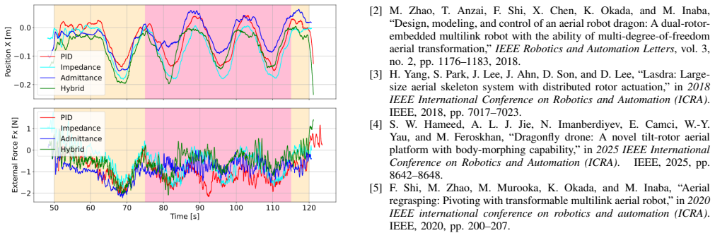
- The four-controller comparison provides evidence that the hybrid controller inherits the strengths of each paradigm: tracking accuracy close to impedance-only control and contact-force reduction close to admittance-only control.
- The framework points toward a principled way to exploit structural redundancy in aerial robots: each actuation source can own the control paradigm it is physically best suited to implement.
Where Pith is reading between the lines
- If extended to overactuated or higher-DOF platforms, the same split could allow admittance behavior on more than one axis, potentially letting the robot conform to curved surfaces rather than only planar slopes; the paper itself lists this as future work.
- The one-dimensional admittance model implies the framework is currently tuned for environments whose geometric variation is mostly along the contact direction; a surface curved in the sliding plane would require a higher-dimensional admittance mapping to retain the claimed adaptivity.
- One testable extension: applying the same hybrid split to inspection tasks such as pipe following or wall crawling, where the contact direction is locally known but the surface profile is not, could yield similar resilience without retuning the impedance/admittance gains.
- The performance improvement over PID at comparable tracking accuracy suggests that the hybrid architecture might reduce tuning effort in practice, since it does not require an explicit surface model or friction estimate.
Editorial analysis
A structured set of objections, weighed in public.
Referee Report
Summary. The paper proposes a hybrid impedance–admittance control framework for a multi-link aerial robot performing contact-rich surface-sliding tasks. Rotor thrust is used to realize impedance behavior on the CoG (mainly along the sliding directions), while joint actuation is used to realize admittance behavior along the contact direction (x-axis). The authors derive an external-wrench estimator, formulate the hybrid controller, and validate it with real-world experiments on a planar board with an unknown slope and unknown friction, comparing the hybrid controller against PID, impedance-only, and admittance-only baselines. The reported results show that the hybrid controller yields median y-error 0.083 m (comparable to impedance-only's 0.079 m) and x-displacement 0.084 m (comparable to admittance-only's 0.088 m), supporting the claim that the hybrid design combines the strengths of both paradigms.
Significance. If the technical derivation and implementation details are correct, the central idea is significant: exploiting the multi-link morphology to assign impedance and admittance control to different physical actuation sources (rotors vs. joints) is a conceptually clean way to circumvent the causality conflict between the two paradigms. The four-controller hardware comparison is a genuine strength, and the experimental data are presented with box plots rather than anecdotal trajectories. However, the contribution is currently weakened by several load-bearing technical issues in the equations and by an overstatement of the generalization to 'unknown surfaces.' With corrections and clarifications, the paper could be a useful contribution to aerial manipulation and force-control architecture design.
major comments (4)
- [§III.C.1, Eq. (7a) and Eq. (9)] The impedance law in Eq. (7a) is written as M_d ddot p + C_td e_v + K_td e_p = f_ext, which omits the reference-acceleration term M_d ddot p_ref. The standard impedance relation is M_d(ddot p - ddot p_ref) + C_td e_v + K_td e_p = f_ext. Since the reference trajectory in Sec. IV.B is a circle of radius 0.30 m with period 14 s, ddot p_ref is not zero, and Eq. (9) is consequently missing the feedforward term m ddot p_ref. The same issue appears in the rotational part, Eq. (7b)/(15), where I_d dot omega_ref is omitted. Please either correct the equations or explicitly state and justify any assumption that reference acceleration/angular acceleration is zero.
- [§III.C.2, Eqs. (19)–(20)] There is an algebraic inconsistency between Eq. (19) and Eq. (20). With ddot r_ref = dot r_ref = 0, Eq. (19) gives m_a ddot r = k_a(r_ref - r) - c_a dot r - (f_hat_ext,x - f_ref,x), i.e., ddot r = [k_a(r_ref-r) - c_a dot r - (f_hat-f_ref)]/m_a. The update in Eq. (20) is the negative of this expression. If the implemented controller really uses Eq. (20), the sign convention must be explained; otherwise the discrete admittance law is not the discretization of Eq. (19). Since this update determines the joint-angle deformation, this is a load-bearing issue for the admittance behavior.
- [§IV.B, Eq. (23)] The mapping between the admittance state r and the configuration angle theta is never specified. The text states that theta 'is defined as the variable in the admittance controller' and gives q1 = pi/2 - theta, q2 = 2theta, q3 = -theta, but it does not provide the forward or inverse kinematic relation r = f(theta) or theta = g(r). Consequently, the reader cannot verify that the r updated by Eq. (21) is actually realized by the one-parameter joint curve, and the reported experiments are not fully reproducible. Please provide this mapping explicitly.
- [§IV.B and §V] The claim of 'adaptive sliding on unknown surfaces' is stronger than what the experiment supports. The validation uses a single planar board with an unknown slope (about 20°). The paper asserts that this 'serves the same role as curved surfaces,' but no argument or data supports that analogy. A planar slope is a one-dimensional geometry variation, which matches the one-dimensional admittance parameterization (single theta in Eq. (23)); a curved or spatially varying surface would generally require more than one deformation parameter. The conclusion should be scoped to 'planar surfaces with unknown inclination and friction,' or the paper should include a curved-surface experiment. This is acknowledged as future work in §V, but the abstract and conclusion still overclaim.
minor comments (5)
- [§IV.B] There is a typo: 'necessity of of the hybrid design' should be 'necessity of the hybrid design.'
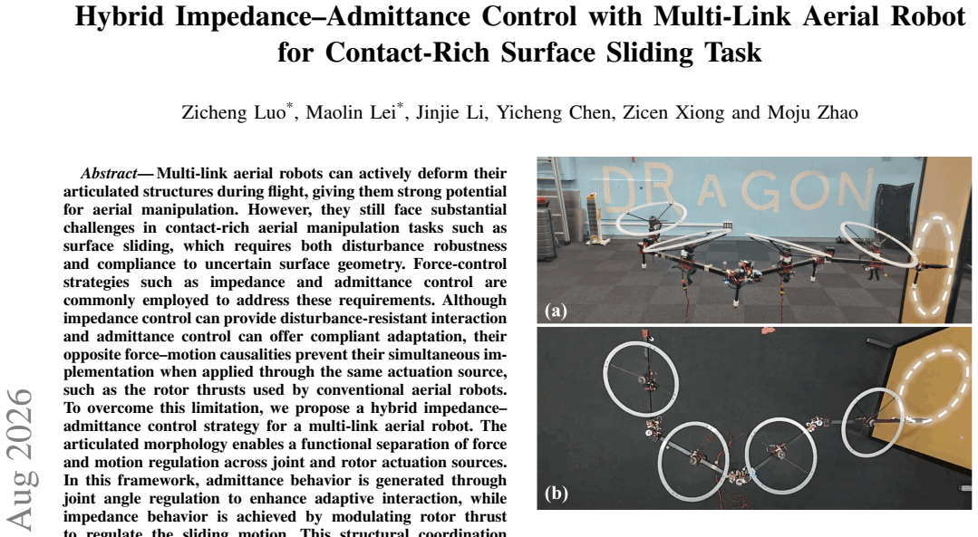
- [Fig. 6] The caption uses '(b) Top view' with a lowercase 'b' while (a) uses 'Front view.' Please make the capitalization consistent.
- [§IV.A] The normalized damping matrices are defined in Eq. (22) using damping ratios Z_td and Z_rd, but the notation Z_td and Z_rd is introduced only just before Eq. (22). It would help to define these symbols explicitly when they first appear in the experimental parameters.
- [§III.C.2] In Eq. (19), it is stated that r is 'the distance between the end effector and the CoG along the x axis,' but the sign convention for r (positive direction) is not specified relative to the world frame in Fig. 4. Please clarify the sign convention, especially because the admittance update and the external force sign interact.
- [General] No statistical significance tests or multiple-run summaries are reported for the box-plot comparisons; e.g., the hybrid vs. impedance-only median y-error difference is small (0.083 vs. 0.079 m). A statement on whether these are single trials or repeated trials, and any variability across runs, would strengthen the experimental claims.
Circularity Check
No significant circularity: the hybrid control claim rests on independent comparative experiments; the θ-parameterization gap is an under-specification, not a circular reduction.
full rationale
The paper's central claim is an architecture plus an experimental demonstration, not a derivation that reduces to its own inputs. The impedance law (Eqs. 7–10) and admittance law (Eqs. 19–21) are standard formulations, and the proposed hybrid combination is evaluated against a manual PID baseline and two ablated controllers on a physical platform. This four-way comparison provides external, falsifiable evidence that does not depend on the paper's own fitted values. Self-citations to [1] are used for platform hardware, the quasi-static assumption, and thrust-allocation details; these are supporting model facts, not an unverified theorem that forces the central claim. The weakest step—the scalar distance r in Eq. (19) being related to a single configuration angle θ via Eq. (23) without an explicit forward/inverse kinematic mapping—is an under-specification and a generalization risk, since the experimental surface is a sloped plane rather than a curved surface (as the conclusion's future-work sentence concedes). But this is not circular: the admittance law is not defined in terms of the experimental outcomes it is used to explain, and no fitted parameter is renamed as a prediction. No load-bearing reduction by construction or self-citation chain is present.
Axiom & Free-Parameter Ledger
free parameters (10)
- Impedance virtual mass ratio M_d/m =
diag(1.0, 3.0, 1.0)
- Impedance virtual inertia ratio I_d * I^-1 =
diag(10.0, 10.0, 5.0)
- Normalized linear stiffness K_td =
diag(2.5, 2.5, 1.5)
- Normalized rotational stiffness K_rd =
diag(40.0, 40.0, 10.0)
- Linear damping ratio Z_td =
diag(0.6, 0.6, 0.7)
- Rotational damping ratio Z_rd =
diag(1.1, 1.1, 0.8)
- External wrench estimator gains K_ti and K_ri =
K_ti=diag(3,3,3), K_ri=diag(1,1,1)
- Admittance mass/damping/stiffness m_a, c_a, k_a =
ma=40 kg, ca=55 N*s/m, ka=16 N/m
- Admittance reference force f_ref,x =
0
- Nominal configuration angle theta =
pi/6
axioms (5)
- domain assumption Variations in the configuration-dependent inertial matrix I(q, psi) are negligible within one control period (quasi-static system).
- domain assumption The estimated external wrench W_f_ext and C_tau_ext approximate the true wrench after first-order filtering.
- domain assumption The surface-geometry uncertainty is one-dimensional along the contact x-axis and can be represented by the scalar r and the single configuration angle theta.
- domain assumption The robot is underactuated, so translational and rotational pose control are cascaded.
- standard math Moore-Penrose pseudoinverse gives a valid thrust allocation for rotational command torque.
Cite this review
Pith. "Pith review of Hybrid Impedance-Admittance Control with Multi-Link Aerial Robot for Contact-Rich Surface Sliding Task." pith.science (2026). https://pith.science/paper/FJXYPT3V
@misc{pith2026260801800,
  author       = {Pith},
  title        = {Pith review of: Hybrid Impedance-Admittance Control with Multi-Link Aerial Robot for Contact-Rich Surface Sliding Task},
  year         = {2026},
  howpublished = {\url{https://pith.science/paper/FJXYPT3V}},
  note         = {Machine review of arXiv:2608.01800}
}
read the original abstract
Multi-link aerial robots can actively deform their articulated structures during flight, giving them strong potential for aerial manipulation. However, they still face substantial challenges in contact-rich aerial manipulation tasks such as surface sliding, which requires both disturbance robustness and compliance to uncertain surface geometry. Force-control strategies such as impedance and admittance control are commonly employed to address these requirements. Although impedance control can provide disturbance-resistant interaction and admittance control can offer compliant adaptation, their opposite force--motion causalities prevent their simultaneous implementation when applied through the same actuation source, such as the rotor thrusts used by conventional aerial robots. To overcome this limitation, we propose a hybrid impedance--admittance control strategy for a multi-link aerial robot. The articulated morphology enables a functional separation of force and motion regulation across joint and rotor actuation sources. In this framework, admittance behavior is generated through joint angle regulation to enhance adaptive interaction, while impedance behavior is achieved by modulating rotor thrust to regulate the sliding motion. This structural coordination allows the robot to leverage the complementary strengths of both control paradigms. As a result, the multi-link aerial robot achieves resilient and adaptive surface sliding. Experimental results demonstrate robust and compliant sliding performance on unknown surfaces.
Figures



Reference graph
Works this paper leans on
-
[1]
M. Zhao, T. Anzai, K. Okada, K. Kawasaki, and M. Inaba, “Singularity-free aerial deformation by two-dimensional multilinked aerial robot with 1-dof vectorable propeller,”IEEE Robotics and Automation Letters, vol. 6, no. 2, pp. 1367–1374, 2021
work page 2021
-
[2]
M. Zhao, T. Anzai, F. Shi, X. Chen, K. Okada, and M. Inaba, “Design, modeling, and control of an aerial robot dragon: A dual-rotor- embedded multilink robot with the ability of multi-degree-of-freedom aerial transformation,”IEEE Robotics and Automation Letters, vol. 3, no. 2, pp. 1176–1183, 2018
work page 2018
-
[3]
Lasdra: Large- size aerial skeleton system with distributed rotor actuation,
H. Yang, S. Park, J. Lee, J. Ahn, D. Son, and D. Lee, “Lasdra: Large- size aerial skeleton system with distributed rotor actuation,” in2018 IEEE International Conference on Robotics and Automation (ICRA). IEEE, 2018, pp. 7017–7023
work page 2018
-
[4]
Dragonfly drone: A novel tilt-rotor aerial platform with body-morphing capability,
S. W. Hameed, A. L. J. Jie, N. Imanberdiyev, E. Camci, W.-Y . Yau, and M. Feroskhan, “Dragonfly drone: A novel tilt-rotor aerial platform with body-morphing capability,” in2025 IEEE International Conference on Robotics and Automation (ICRA). IEEE, 2025, pp. 8642–8648
work page 2025
-
[5]
Aerial regrasping: Pivoting with transformable multilink aerial robot,
F. Shi, M. Zhao, M. Murooka, K. Okada, and M. Inaba, “Aerial regrasping: Pivoting with transformable multilink aerial robot,” in2020 IEEE international conference on robotics and automation (ICRA). IEEE, 2020, pp. 200–207
work page 2020
-
[6]
M. Zhao, K. Okada, and M. Inaba, “Versatile articulated aerial robot dragon: Aerial manipulation and grasping by vectorable thrust control,”The International Journal of Robotics Research, vol. 42, no. 4-5, pp. 214–248, 2023
work page 2023
-
[7]
N. Sugito, M. Zhao, T. Anzai, T. Nishio, K. Okada, and M. Inaba, “Aerial manipulation using contact with the environment by thrust vectorable multilinked aerial robot,” in2022 International Conference on Robotics and Automation (ICRA). IEEE, 2022, pp. 54–60
work page 2022
-
[8]
M. Zhao, K. Nagato, K. Okada, M. Inaba, and M. Nakao, “Force- ful valve manipulation with arbitrary direction by articulated aerial robot equipped with thrust vectoring apparatus,”IEEE Robotics and Automation Letters, vol. 7, no. 2, pp. 4893–4900, 2022
work page 2022
-
[9]
Active interaction force control for contact- based inspection with a fully actuated aerial vehicle,
K. Bodie, M. Brunner, M. Pantic, S. Walser, P. Pf ¨andler, U. Angst, R. Siegwart, and J. Nieto, “Active interaction force control for contact- based inspection with a fully actuated aerial vehicle,”IEEE Transac- tions on Robotics, vol. 37, no. 3, pp. 709–722, 2020
work page 2020
-
[10]
M. ´A. Trujillo, J. R. Mart ´ınez-de Dios, C. Mart ´ın, A. Viguria, and A. Ollero, “Novel aerial manipulator for accurate and robust industrial ndt contact inspection: A new tool for the oil and gas inspection industry,”Sensors, vol. 19, no. 6, p. 1305, 2019
work page 2019
-
[11]
M. Tognon, H. A. T. Ch ´avez, E. Gasparin, Q. Sabl ´e, D. Bicego, A. Mallet, M. Lany, G. Santi, B. Revaz, J. Cort ´eset al., “A truly- redundant aerial manipulator system with application to push-and-slide inspection in industrial plants,”IEEE Robotics and Automation Letters, vol. 4, no. 2, pp. 1846–1851, 2019
work page 2019
-
[12]
Past, present, and future of aerial robotic manipulators,
A. Ollero, M. Tognon, A. Suarez, D. Lee, and A. Franchi, “Past, present, and future of aerial robotic manipulators,”IEEE Transactions on Robotics, vol. 38, no. 1, pp. 626–645, 2021
work page 2021
-
[13]
W. Zhang, L. Ott, M. Tognon, and R. Siegwart, “Learning variable impedance control for aerial sliding on uneven heterogeneous surfaces by proprioceptive and tactile sensing,”IEEE Robotics and Automation Letters, vol. 7, no. 4, pp. 11 275–11 282, 2022
work page 2022
-
[14]
6d interaction control with aerial robots: The flying end-effector paradigm,
M. Ryll, G. Muscio, F. Pierri, E. Cataldi, G. Antonelli, F. Caccav- ale, D. Bicego, and A. Franchi, “6d interaction control with aerial robots: The flying end-effector paradigm,”The International Journal of Robotics Research, vol. 38, no. 9, pp. 1045–1062, 2019
work page 2019
-
[15]
Unified impedance and ad- mittance control,
C. Ott, R. Mukherjee, and Y . Nakamura, “Unified impedance and ad- mittance control,” in2010 IEEE international conference on robotics and automation. IEEE, 2010, pp. 554–561
work page 2010
-
[16]
Cartesian impedance control of a uav with a robotic arm,
V . Lippiello and F. Ruggiero, “Cartesian impedance control of a uav with a robotic arm,”IF AC Proceedings V olumes, vol. 45, no. 22, pp. 704–709, 2012
work page 2012
-
[17]
Impedance control of an aerial-manipulator: Preliminary results,
E. Cataldi, G. Muscio, M. A. Trujillo, Y . Rodr ´ıguez, F. Pierri, G. Antonelli, F. Caccavale, A. Viguria, S. Chiaverini, and A. Ollero, “Impedance control of an aerial-manipulator: Preliminary results,” in 2016 IEEE/RSJ International Conference on Intelligent Robots and Systems (IROS). IEEE, 2016, pp. 3848–3853
work page 2016
-
[18]
T. Anzai, M. Zhao, M. Murooka, F. Shi, K. Okada, and M. Inaba, “Design, modeling and control of fully actuated 2d transformable aerial robot with 1 dof thrust vectorable link module,” in2019 IEEE/RSJ International Conference on Intelligent Robots and Systems (IROS). IEEE, 2019, pp. 2820–2826
work page 2019
-
[19]
Impedance control of vtol uavs with a momentum-based external generalized forces estimator,
F. Ruggiero, J. Cacace, H. Sadeghian, and V . Lippiello, “Impedance control of vtol uavs with a momentum-based external generalized forces estimator,” in2014 IEEE international conference on robotics and automation (ICRA). IEEE, 2014, pp. 2093–2099
work page 2014
This paper was first reviewed by deepseek-v4-flash on August 4, 2026.
discussion (0)
Sign in with ORCID, Apple, or X to comment. Anyone can read and Pith papers without signing in.