REVIEW 4 major objections 7 minor 38 references
Integrating polynomial battery and propulsion models into NMPC with in-flight replanning keeps high-speed UAVs on shrinking thrust limits, cutting tracking error sixfold and doubling flight time in obstacle fields.
Reviewed by Pith at T0; open to challenge. T0 means a machine referee read the full paper against a public rubric. the ladder, T0–T4 →
T0 review · grok-4.5
2026-07-30 14:00 UTC pith:3MQFXC5U
load-bearing objection Solid real-time NMPC integration of fitted battery/propulsion polynomials with outdoor electrical validation; the abstract’s 6×/46%/100% numbers are sim-only under stressed mass and negative-SOC extrapolation. the 4 major comments →
BC-NMPC: Battery-Constrained NMPC with Propulsion Prediction and Replanning for High-Speed Flight
The pith
A machine-rendered reading of the paper's core claim, the machinery that carries it, and where it could break.
Core claim
A multivariate-polynomial electro-mechanical propulsion model, carried as SOC dynamics and a state-dependent collective-thrust constraint inside NMPC and paired with online replanning under the predicted T_max, produces collision-free high-speed flight whose tracking RMSE falls six-fold while distance and time rise 46 percent and 100 percent relative to thrust-unaware control in an obstacle-ridden environment.
What carries the argument
BC-NMPC: the battery-constrained NMPC that treats state-of-charge as a dynamic state, evaluates fitted polynomials relating throttle, voltage, resistance, power and thrust, enforces the resulting time-varying T_max as a nonlinear input constraint, and triggers a PMM trajectory replanner whenever available acceleration changes.
Load-bearing premise
Polynomials fitted on a static thrust stand, plus one temperature scale factor from a short calibration flight, remain accurate enough under high advance-ratio airflow that the predicted thrust ceiling can safely drive both the controller and the replanner.
What would settle it
Repeat the obstacle-course comparison on the physical aircraft (not only the mass-inflated simulator) with and without the thrust-aware constraint and replanning, and check whether measured RMSE, collisions, distance and flight time reproduce the reported six-fold / zero-collision / +46 percent / +100 percent gains; or log predicted versus load-cell maximum thrust once the vehicle is flying at high advance ratio.
If this is right
- Multi-rotor controllers can stay at the instantaneous thrust limit across a full discharge instead of using fixed conservative margins.
- Time-optimal racing or inspection paths remain feasible longer because they are refreshed whenever available acceleration shrinks.
- Remaining range and endurance can be recomputed online from desired thrust alone when payload or wind changes.
- Obstacle-dense missions no longer trade large tracking lag for collision risk once thrust headroom is predicted rather than assumed constant.
Where Pith is reading between the lines
- The same polynomials could also soften single-rotor thrust limits inside the low-level allocator, closing the cascaded-control gap left open by the paper.
- Replacing the constant temperature scale with an online resistance update would likely cut residual current error and extend the method to cold or high continuous-C packs.
- If the stack transfers to Li-ion chemistries with steeper load sag, long-endurance inspection drones would gain the same mid-mission limit awareness shown here for racing LiPos.
Editorial analysis
A structured set of objections, weighed in public.
Referee Report
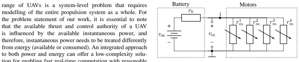
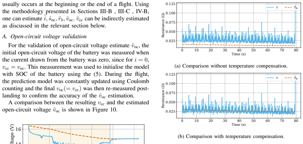
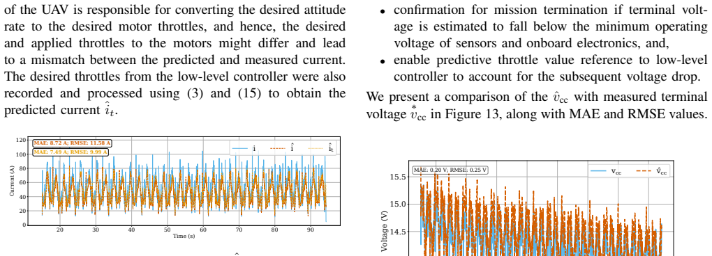
Summary. The paper presents BC-NMPC, a quadrotor NMPC formulation that integrates multivariate polynomial models of the motor-propeller unit (thrust/power/resistance as functions of throttle, voltage, RPM; eqs. 1-4) and of a 4S LiPo battery (IR model with v_oc(soc), r_b(soc) cubics; eqs. 5-7) to predict, in real time, terminal voltage, current, power, and maximum available collective thrust T_max (eqs. 15-16). T_max enters the OCP as a nonlinear constraint (eq. 17), and a PMM-based planner replans the trajectory in flight as the thrust limit shrinks. The component models are validated on a static full-airframe bench test (Fig. 8) and in outdoor lemniscate flights at up to 23 m/s and 44 m/s^2 down to ~300 mAh SOC (§VI), with post-landing v_oc consistency, a temperature-compensated r_b, terminal-voltage MAE of 0.20 V, ~17% current error, and mean NMPC solve time of 5 ms. The headline performance claims — collision-free flight, 6-fold RMSE reduction, +46% distance, +100% flight time versus uncompensated flight — come exclusively from a simulation study (§VII, Table III) in which the aircraft mass is increased to 1.54 kg and the battery is allowed to discharge into negative SOC.
Significance. If the claims hold, the contribution is meaningful for agile UAV flight: a closed-form propulsion/battery model fast enough to run inside NMPC at 100 Hz (mean solve time 5 ms, Fig. 14), validated in genuinely aggressive real flight (23 m/s, 44 m/s^2), with in-flight replanning against evolving thrust limits. The identification-then-validation methodology (bench identification, separate flight telemetry validation) is sound, and the paper is refreshingly explicit about its error budget. However, the headline quantitative gains rest entirely on a simulation whose decisive regime (negative SOC, increased mass) lies outside the validated model domain, so the significance of the numerical claims is currently overstated relative to what is demonstrated.
major comments (4)
- [§VII, eqs. (6)-(7), (15)-(16), Table II] The battery polynomials v_oc(soc) (eq. 7) and r_b(soc) (eq. 6) are cubics fitted on discharge data over roughly 300-3300 mAh (Fig. 7, §VI), yet §VII explicitly 'allowed [the battery] to discharge into negative SOC.' Cubics extrapolated past the fit domain are unconstrained; evaluating the Table II coefficients at soc = -1000 mAh gives v_oc ≈ 12.9 V and r_b ≈ 0.013 Ohm — a gentle, smooth decay. A real 4S LiPo near and below empty exhibits a sharp voltage knee and a steep internal-resistance rise, neither of which a cubic can represent. Since T_max is computed from v_oc and r_b via eqs. (15)-(16), the extrapolation keeps predicted T_max artificially high late in flight. This directly sets the replanning case's flight time (234.4 s) and distance (2.96 km) — the numerators of the headline '+100% flight time / +46% distance' claims — and also shifts the baseline collision times (117.2 s / 131
- [§VII, Table III] The digital twin's mass was raised from the real 1.2 kg to 1.54 kg 'to highlight the performance degradation.' This places hover thrust (~15 N) and the 3.5 g Required Thrust Threshold (52.8 N) close to the ~65 N ceiling, so collision/termination times become highly sensitive to small T_max errors. Given the acknowledged 15-17% current-estimation error (§VI-C) and the extrapolated T_max of Major Comment 1, an error of 1-2 N in predicted T_max can plausibly move the flight-end and collision times in Table III by tens of seconds. The headline gains are therefore specific to a configuration that is both non-physical (heavier than the real aircraft) and operating in an unvalidated battery regime. At minimum, a sensitivity analysis over mass/RTT margin, or a rerun at the real mass, is needed to show the qualitative conclusion (replanning prevents collision) is robust rather than an artifact of
- [Abstract; §VIII] The abstract and conclusion state 'a 6-fold decrease in tracking RMSE, a 46% increase in flight distance, and a 100% increase in flight time in an obstacle-ridden environment' without qualification. Per the manuscript itself, these numbers come exclusively from the §VII simulation with increased mass and negative-SOC extrapolation; the real-world experiments (§VI) validate only the component predictions (v_oc, r_b, i, v_cc, solve time), and no real flight demonstrates the replanning benefit or a collision-avoidance outcome. The claims should be explicitly scoped as simulation results obtained under a modified configuration, and the abstract should not present them as demonstrated flight performance.
- [§IV-B, eq. (17); §VI-C] The nonlinear constraint (17) enforces sum_i f_i <= T_max,k using the raw predicted T_max with no safety margin, while §VI-C acknowledges ~17% current error (8.72 A MAE on a 50.71 A mean) attributed to unmodeled advance-ratio torque, sensor scaling, and battery recovery. Since T_max derives from the same v_oc/r_b/p_in chain, a comparable relative error on T_max is plausible; the manuscript never quantifies the T_max prediction error in flight (Fig. 8 validates T_max only at 100% throttle on the bench, i.e., static conditions). For a controller whose stated purpose is to fly 'at the constantly-changing platform limits,' the error budget of the limit itself should be characterized in dynamic flight, or a margin/robustification of (17) discussed.
minor comments (7)
- [Throughout] Numerous typos: 'demonstrates achieves' (abstract), 'dicuss' (§III-A), 'Therfore' (§IV-A), 'therfore' (§IV-B), 'mistmatch' (§VI-B), 'betwen' (Fig. 3 caption), 'examplesof' (§VI-E), 'upto' (multiple).
- [§IV-A, eq. (8)] Eq. (8): soc_dot = -i mixes units — soc is in mAh (Figs. 7, 10) while i is in A; the required 1000/3600 conversion factor should be stated for reproducibility of the RK4 integration.
- [§IV-B, eq. (15)] Eq. (15) uses r_m for the parallel combination of the four motor resistances, while eq. (3) and Fig. 2 define r_m per motor; the notation should distinguish r_m,parallel from r_m,i.
- [§VI-B, eq. (19)] §VI-B: the temperature-compensation coefficient K_t (eq. 19) is obtained from 'a short calibration flight,' but it is not stated whether battery temperature is measured in flight, how K_t generalizes across ambient temperatures, or whether the validation flights of Fig. 11b are independent of the calibration flight. Please clarify.
- [Figs. 10-11] Fig. 11 legends appear garbled ('r r̂_b'); the estimated vs. measured curves are hard to distinguish. Fig. 10: the legend for the two traces is missing/unclear.
- [§IV-B, eq. (16)] Eq. (16): writing T_max = 4(a_t v_cc^2 + b_t v_cc + d_t v_cc + c_t + e_t) would be clearer as the direct th=1 substitution of eq. (4), i.e., 4(a_t v_cc^2 + (b_t + d_t) v_cc + (c_t + e_t)); please check the printed grouping.
- [References; §II-C] Reference [20] is listed as 2024 but the arXiv identifier is from 2021; also verify the claim in §II-C ('to the best of our knowledge, the first approach...') against recent literature, since it is a strong novelty statement.
Simulated Author's Rebuttal
We thank the referee for a careful and technically precise report. We agree with the central observation: the headline quantitative gains (6-fold RMSE, +46% distance, +100% flight time) are produced in a simulation that deliberately exaggerates the degradation regime by increasing mass to 1.54 kg and by allowing SOC to go negative, i.e., outside the domain in which the battery polynomials were identified (roughly 300-3300 mAh). We will revise to (i) scope all headline numbers explicitly as simulation results under a modified configuration, (ii) add a sensitivity study over mass/RTT margin and a rerun at the real 1.2 kg mass with SOC clamped at the validated lower bound, and (iii) characterize the T_max prediction error and discuss a safety margin on constraint (17). We maintain that the component-model validation (23 m/s, 44 m/s^2 real flight, 0.20 V terminal-voltage MAE, 5 ms solve time) stands on its own within the validated domain; what requires correction is the presentation and robustness evidence for the system-level claims, not the modeling methodology itself.
read point-by-point responses
-
Referee: Battery cubics v_oc(soc), r_b(soc) fitted over 300-3300 mAh are extrapolated into negative SOC in §VII, where a real 4S LiPo has a sharp voltage knee and steep r_b rise. This keeps predicted T_max artificially high and directly sets the 234.4 s / 2.96 km headline numbers.
Authors: We agree this is the decisive weakness of the simulation study, and we thank the referee for the concrete coefficient evaluation at soc = -1000 mAh, which makes the issue unambiguous. The negative-SOC discharge was intended as a qualitative stress test ('exaggerate the effects... for heavy aircraft and low-discharge chemistries', §VII), but the manuscript does not make clear that the resulting numbers inherit an unphysical smooth decay. In the revision we will: (1) re-run the §VII experiments with the SOC evolution clamped at the validated lower bound (~300 mAh) and a hard termination when v_oc(soc) reaches the fit-domain minimum, reporting flight time/distance/RMSE for all three cases under the clamped model; (2) add a supplementary run with a phenomenological knee model (e.g., sharp v_oc drop and r_b rise below the fit domain) to show how the replanning case behaves when the extrapolation is pessimistic rather than generous. We expect the qualitative ordering (replanning collision-free; baselines collide) to survive because the replanner's benefit accrues while SOC is still well inside the validated range, but the exact '+100% flight time' figure will change and will be reported as a clamped-model number with the knee-model result as a robustness bound. revision: yes
-
Referee: The digital twin mass was raised to 1.54 kg, making hover thrust and the 52.8 N RTT sit close to the ~65 N ceiling, so Table III outcomes are highly sensitive to small T_max errors given the acknowledged 15-17% current error. A sensitivity analysis over mass/RTT margin or a rerun at real mass is needed.
Authors: We agree a sensitivity analysis is necessary and will add it. The mass increase was chosen to make the degradation observable within a short simulated flight, but the manuscript presents the resulting numbers without acknowledging that they sit in a knife-edge regime. In the revision we will: (1) rerun all three cases at the real 1.2 kg mass with the clamped battery model; (2) sweep mass in, e.g., 0.1 kg steps between 1.2 and 1.54 kg and report collision time, flight time, distance, and mean RMSE for each of the three configurations; (3) report the margin between RTT and T_max over time for each run, so the reader can see where each case operates relative to the ceiling. This will demonstrate whether the qualitative conclusion (replanning prevents collision and extends safe flight) holds across the margin range or only near the 1.54 kg configuration, and we will state the outcome honestly either way. revision: yes
-
Referee: Abstract and §VIII present the 6-fold RMSE / +46% / +100% figures without qualification, though they come only from the §VII simulation with increased mass and negative-SOC extrapolation; no real flight demonstrates replanning benefit or collision avoidance.
Authors: This is correct and we will fix it. The abstract will be rewritten to state explicitly that model accuracy was validated in real-world flight experiments while the performance gains were demonstrated in simulation under a modified (heavier) configuration, e.g.: 'The accuracy of the proposed model is verified in real-world flight experiments up to 23 m/s and 44 m/s^2; in simulation with a deliberately degraded thrust-to-weight margin, the approach achieves a 6-fold decrease in tracking RMSE, a 46% increase in flight distance, and a 100% increase in flight time relative to an uncompensated flight.' Section VIII will be amended identically, and the numbers will be updated to the clamped-model results of the revision. We will also state explicitly that real-flight demonstration of the replanning loop is future work. We note the original abstract already contains the sentence distinguishing simulation evaluation of replanning, but we agree the claims sentence that follows effectively overrides it and must be scoped. revision: yes
-
Referee: Constraint (17) uses raw predicted T_max with no safety margin, while §VI-C acknowledges ~17% current error that plausibly propagates to T_max. T_max prediction error is never quantified in dynamic flight (Fig. 8 is static, 100% throttle). The error budget of the limit itself should be characterized or a margin on (17) discussed.
Authors: We agree the T_max error budget in dynamic flight is under-characterized. Two points of context, then our planned revision. First, the error propagation is not one-to-one: T_max depends on v_cc at full throttle through (15)-(16), and since r_b is small relative to the parallel motor resistance at th=1, a 17% current error translates to a considerably smaller relative error on v_cc and hence on T_max; the static bench validation (Fig. 8a) shows close T_max agreement at full throttle across the discharge. Nevertheless, this is only a static check. In the revision we will: (1) extract a dynamic T_max error estimate from the existing flight telemetry by comparing predicted T_max against the thrust actually attained at throttle-saturation segments of the §VI flights; (2) reformulate (17) with a configurable margin, sum_i f_i <= (1-epsilon) T_max,k, report the epsilon implied by the measured error, and discuss the tracking-performance cost of the margin; (3) include the margin in the revised §VII sensitivity study so the replanning benefit is shown to hold under a conservative limit, not a nominal one. revision: partial
- We cannot fully resolve the negative-SOC extrapolation critique with new data: extending the battery identification below ~300 mAh on the bench (and especially under flight-representative load profiles at very low SOC) risks cell damage and requires new hardware campaigns not feasible within a normal revision cycle. We will address it via clamped-model reruns and a phenomenological knee model, but an experimentally identified sub-300 mAh model remains future work.
- A real-flight demonstration of the replanning benefit (the referee's implicit gold standard behind comments 2 and 3) cannot be produced in this revision; we can only re-scope the claims and strengthen the simulation evidence.
Circularity Check
Ordinary system-ID-plus-validation and closed-loop use of fitted polynomials; no load-bearing prediction is forced by construction.
specific steps
-
fitted input called prediction
[§III-B, Fig. 5, eq. (4)]
"For any given combination of voltage and throttle, the ‘Moseler model‘ can be used to predict the thrust produced by the motor-propeller system, and compared to the thrust predicted by ‘BC-NMPC‘ through (4). The actual thrust measurements from the thrust stand were used to calculate an absolute error in the predictions of both models, and the results are shown in Figure 5. As seen from the figure, our proposed model performs significantly better than the ‘Moseler model‘"
Eq. (4) is a polynomial surface fitted directly to the same static thrust-stand (v_cc, th, f) points against which absolute error is then plotted. Lower error than Moseler on that set is largely guaranteed by construction (flexible polynomial vs. a fixed electro-mechanical structure) and is not an out-of-sample prediction. The slip is local to Fig. 5; flight telemetry and sim policy comparisons use held-out conditions and are not forced by this fit.
full rationale
The derivation chain is: (i) fit multivariate polynomials for motor–propeller maps (eqs. 1–4, Table I) and IR battery maps (eqs. 5–7, Table II) on dedicated bench/discharge rigs; (ii) optionally scale rb by a single temperature coefficient Kt from a short calibration flight (eq. 19); (iii) embed the resulting T_max(soc) and current maps as NMPC constraints and as inputs to an external PMM replanner; (iv) compare predicted v_oc, rb, i, v_cc and T_max against separate full-UAV thrust-stand and outdoor lemniscate telemetry; (v) in simulation, contrast thrust-unaware / thrust-aware-no-replan / thrust-aware-replan policies. None of the headline quantities (RMSE, distance, time, collision-free status) is defined in terms of the fitted coefficients, nor is any uniqueness theorem imported from overlapping-author work to forbid alternatives. Self-citations ([21], [33], [35]) supply the planner, prior NMPC scaffolding, and stack—not the propulsion claim. The only mild slip is Fig. 5, where BC-NMPC thrust error is reported on the same static-stand data used to fit eq. 4; that comparison is in-sample and does not underwrite the flight or simulation claims. Extrapolation of the cubics past the fitted SOC range in the negative-SOC simulation is a correctness/validity concern, not circularity: the model is still an external map, not a tautology. Score 1 for that single minor in-sample comparison; central results remain independently checked.
Axiom & Free-Parameter Ledger
free parameters (6)
- Motor polynomial coefficients (af,bf,cf; ap,bp,cp; ar…hr; at…et) =
Table I values (e.g. af=5.376e-8, ap=1.082, ar=-1157.76, …)
- Battery polynomial coefficients (as…ds; ad…dd; aq…dq) =
Table II values
- Temperature compensation Kt on Rb =
Not numerically reported; applied as Rb*=Kt*poly(SOC)
- NMPC weights Q, R, T and horizon N =
Not specified numerically in the text
- Drag coefficients kvx, kvy, kvz and torque constant κ, inertia J, mass m =
Real mass 1.2 kg; sim mass 1.54 kg; others not fully tabulated
- Required thrust threshold / planned acceleration (3.5 g → RTT 52.8 N in sim) =
3.5 g; RTT 52.8 N at 1.54 kg
axioms (6)
- domain assumption Internal-resistance (Thevenin IR) battery model with SOC-dependent VOC and Rb suffices for real-time prediction; inductance and multi-time-constant dynamics can be neglected at NMPC timestep.
- domain assumption Each motor–propeller may be treated as a variable resistive load with steady-state polynomial maps from static thrust-stand data.
- domain assumption SOC is reset per flight and updated by coulomb counting ˙soc=−i with acceptable drift over one discharge.
- ad hoc to paper Collective T_max(SOC) constraint plus low-level rate tracking is enough; per-rotor f_max need not vary with SOC in the NMPC.
- standard math Standard multirotor rigid-body dynamics with linear body-frame drag and RK4 shooting in ACADOS NMPC.
- domain assumption PMM planner produces thrust-limited time-optimal segments fast enough that replanning only at waypoints captures evolving limits.
invented entities (1)
-
BC-NMPC (battery-constrained NMPC with polynomial propulsion prediction)
independent evidence
read the original abstract
Trajectory tracking performance of Uncrewed Aerial Vehicles (UAVs) degrades during high-speed and agile flight due to the depletion of the battery and subsequent loss of maximum available thrust. In applications such as drone racing, the consequent trajectory tracking error leads to a collision with obstacles and a subsequent failure to complete the race. In this paper, we present a novel method for integrating battery and propulsion system models into a Nonlinear Model Predictive Controller (NMPC) framework to enable real-time prediction of the voltage, consumed current, power, and maximum available thrust of the platform. This enables our approach to account for the dynamic variations in the maximum available thrust of the UAV caused by battery discharge, allowing it to plan for the depleting thrust and improve trajectory tracking performance. A trajectory planning algorithm is implemented to replan the trajectory in-flight based on evolving thrust limits. The accuracy of the proposed model is verified in real-world flight experiments, while the effectiveness of the replanning algorithm is evaluated in simulation. Compared to an uncompensated flight, our novel approach demonstrates achieves a collision-free flight to achieve a 6-fold decrease in tracking Root Mean Square Error (RMSE), a 46 % increase in flight distance, and a 100 % increase in flight time in an obstacle-ridden environment.
Figures






Reference graph
Works this paper leans on
-
[1]
Decentralized perimeter surveillance using a team of uavs,
D. Kingston, R. W. Beard, and R. S. Holt, “Decentralized perimeter surveillance using a team of uavs,”IEEE Transactions on Robotics, vol. 24, no. 6, pp. 1394–1404, 2008
2008
-
[2]
Human body detection and geolocalization for uav search and rescue missions using color and thermal imagery,
P. Rudol and P. Doherty, “Human body detection and geolocalization for uav search and rescue missions using color and thermal imagery,” in2008 IEEE Aerospace Conference, 2008, pp. 1–8
2008
-
[3]
Multiple uav formations for cooperative source seeking and contour mapping of a radiative signal field,
J. Han and Y . Chen, “Multiple uav formations for cooperative source seeking and contour mapping of a radiative signal field,”Journal of Intelligent & Robotic Systems, vol. 74, no. 1, pp. 323–332, Apr 2014
2014
-
[4]
Localization of ionizing radiation sources by cooperating micro aerial vehicles with pixel detectors in real-time,
P. ˇStibinger, T. B´aˇca, and M. Saska, “Localization of ionizing radiation sources by cooperating micro aerial vehicles with pixel detectors in real-time,”IEEE Robotics and Automation Letters, vol. 5, no. 2, pp. 3634–3641, 2020
2020
-
[5]
Aerial service robots for visual inspection of thermal power plant boiler systems,
M. Burri, J. Nikolic, C. H ¨urzeler, G. Caprari, and R. Siegwart, “Aerial service robots for visual inspection of thermal power plant boiler systems,” in2nd International Conference on Applied Robotics for the Power Industry, 2012, pp. 70–75
2012
-
[6]
Beyond visual range obstacle avoidance and infrastructure inspection by an autonomous helicopter,
T. Merz and F. Kendoul, “Beyond visual range obstacle avoidance and infrastructure inspection by an autonomous helicopter,” inIEEE/RSJ International Conference on Intelligent Robots and Systems, 2011, pp. 4953–4960
2011
-
[7]
Energy-aware multi-uav coverage mission planning with optimal speed of flight,
D. Datsko, F. Nekovar, R. Penicka, and M. Saska, “Energy-aware multi-uav coverage mission planning with optimal speed of flight,” IEEE Robotics and Automation Letters, vol. 9, no. 3, pp. 2893–2900, 2024
2024
-
[8]
A. Verraest, S. Bahnam, R. Ferede, G. de Croon, and C. D. Wagter, “Skydreamer: Interpretable end-to-end vision-based drone racing with model-based reinforcement learning,” 2025. [Online]. Available: https://arxiv.org/abs/2510.14783
arXiv 2025
-
[9]
Monorace: Winning champion-level drone racing with robust monocular ai,
S. A. Bahnam, R. Ferede, T. M. Blaha, A. E. Lang, E. Lucassen, Q. Missinne, A. E. C. Verraest, C. D. Wagter, and G. C. H. E. de Croon, “Monorace: Winning champion-level drone racing with robust monocular ai,” 2026. [Online]. Available: https://arxiv.org/abs/2601.15222
arXiv 2026
-
[10]
A comparative study of nonlinear mpc and differential-flatness-based control for quadrotor agile flight,
S. Sun, A. Romero, P. Foehn, E. Kaufmann, and D. Scaramuzza, “A comparative study of nonlinear mpc and differential-flatness-based control for quadrotor agile flight,”IEEE Transactions on Robotics, vol. 38, no. 6, pp. 3357–3373, 2022
2022
-
[11]
Agilicious: Open-source and open-hardware agile quadrotor for vision-based flight,
P. Foehn, E. Kaufmann, A. Romero, R. Penicka, S. Sun, L. Bauersfeld, T. Laengle, G. Cioffi, Y . Song, A. Loquercio, and D. Scaramuzza, “Agilicious: Open-source and open-hardware agile quadrotor for vision-based flight,”Science Robotics, vol. 7, no. 67, p. eabl6259,
-
[12]
Time-optimal planning for quadrotor waypoint flight,
P. Foehn, A. Romero, and D. Scaramuzza, “Time-optimal planning for quadrotor waypoint flight,”Science Robotics, vol. 6, no. 56, p. eabh1221, 2021. [Online]. Available: https://www.science.org/doi/abs/ 10.1126/scirobotics.abh1221
-
[13]
Battery modeling,
M. Jongerden and B. Haverkort, “Battery modeling,”CTIT Technical Report Series, no. TR-CTIT-08-01, 01 2008
2008
-
[14]
NeuroBEM: Hybrid Aerodynamic Quadrotor Model,
L. Bauersfeld*, E. Kaufmann*, P. Foehn, S. Sun, and D. Scaramuzza, “NeuroBEM: Hybrid Aerodynamic Quadrotor Model,” inRobotics: Science and Systems XVII. Robotics: Science and Systems Founda- tion, July 2021
2021
-
[15]
A critical review of using the peukert equation for determining the remaining capacity of lead-acid and lithium-ion batteries,
D. Doerffel and S. A. Sharkh, “A critical review of using the peukert equation for determining the remaining capacity of lead-acid and lithium-ion batteries,”Journal of Power Sources, vol. 155, no. 2, pp. 395–400, 2006. [Online]. Available: https: //www.sciencedirect.com/science/article/pii/S0378775305007093
2006
-
[16]
Generalized an- alytical model for capacity evaluation of automotive-grade lithium batteries,
N. Galushkin, N. Yazvinskaya, and D. Galushkin, “Generalized an- alytical model for capacity evaluation of automotive-grade lithium batteries,”Journal of the electrochemical society, vol. 162, no. 3, p. A308, 2014
2014
-
[17]
Modelling of li-ion batteries using equivalent circuit diagrams,
A. Rahmoun and H. Biechl, “Modelling of li-ion batteries using equivalent circuit diagrams,”Przeglad Elektrotechniczny, vol. 88, pp. 152–156, 01 2012
2012
-
[18]
Electrochemical modeling of lithium polymer batteries,
D. W. Dees, V . S. Battaglia, and A. B ´elanger, “Electrochemical modeling of lithium polymer batteries,”Journal of Power Sources, vol. 110, no. 2, pp. 310–320, 2002. [Online]. Available: https: //www.sciencedirect.com/science/article/pii/S0378775302001933
2002
-
[19]
Characterization and comparison between lithium iron p hosphate and lithium-polymers batteries,
F. Sergi, A. Arista, G. Agnello, M. Ferraro, L. Andaloro, and V . An- tonucci, “Characterization and comparison between lithium iron p hosphate and lithium-polymers batteries,”Journal of Energy Storage, vol. 8, pp. 235–243, 2016
2016
-
[20]
Range, endurance, and optimal speed estimates for multicopters,
L. Bauersfeld and D. Scaramuzza, “Range, endurance, and optimal speed estimates for multicopters,” 2024. [Online]. Available: https://arxiv.org/abs/2109.04741
Pith/arXiv arXiv 2024
-
[21]
Real-time planning of minimum-time trajectories for agile uav flight,
K. Teissing, M. Novosad, R. Penicka, and M. Saska, “Real-time planning of minimum-time trajectories for agile uav flight,”IEEE Robotics and Automation Letters, vol. 9, no. 11, p. 10351–10358, Nov. 2024. [Online]. Available: http://dx.doi.org/10.1109/LRA.2024. 3471388
doi:10.1109/lra.2024 2024
-
[22]
An analytical high-level battery model for use in energy management of portable electronic systems
D. Rakhmatov and S. Vrudhula, “An analytical high-level battery model for use in energy management of portable electronic systems.” 02 2001, pp. 488–493
2001
-
[23]
Lead acid battery storage model for hybrid energy systems,
J. F. Manwell and J. G. McGowan, “Lead acid battery storage model for hybrid energy systems,”Solar Energy, vol. 50, no. 5, pp. 399–405, 1993. [Online]. Available: https://www.sciencedirect.com/ science/article/pii/0038092X93900602
arXiv 1993
-
[24]
Stochastic model predictive control for optimal charging of electric vehicles battery packs,
A. Pozzi and D. Raimondo, “Stochastic model predictive control for optimal charging of electric vehicles battery packs,”Journal of Energy Storage, vol. 55, p. 105332, 11 2022
2022
-
[25]
Propulsion System Modeling for Small Fixed-Wing UA Vs,
E. M. Coates, A. Wenz, K. Gryte, and T. A. Johansen, “Propulsion System Modeling for Small Fixed-Wing UA Vs,” in2019 International Conference on Unmanned Aircraft Systems (ICUAS), June 2019, pp. 748–757
2019
-
[26]
Application of model-based fault detection to a brushless DC motor,
O. Moseler and R. Isermann, “Application of model-based fault detection to a brushless DC motor,”IEEE Transactions on Industrial Electronics, vol. 47, no. 5, pp. 1015–1020, Oct. 2000
2000
-
[27]
R. W. BEARD and T. W. McLAIN,Small Unmanned Aircraft: Theory and Practice, 2nd ed. Princeton University Press, 2012. [Online]. Available: http://www.jstor.org/stable/j.ctt7sbc4
2012
-
[28]
Brushless DC motor characterisation and selection for a fixed wing UA V,
D. L. Gabriel, J. Meyer, and F. du Plessis, “Brushless DC motor characterisation and selection for a fixed wing UA V,” inIEEE Africon ’11, Sept. 2011, pp. 1–6
2011
-
[29]
Rotor blade performance analysis with blade element momentum theory,
F. Mahmuddin, “Rotor blade performance analysis with blade element momentum theory,”Energy Procedia, vol. 105, pp. 1123–1129, 2017, 8th International Conference on Applied Energy, ICAE2016, 8- 11 October 2016, Beijing, China. [Online]. Available: https: //www.sciencedirect.com/science/article/pii/S1876610217305180
2017
-
[30]
Improved model for micro-uav propulsion systems: Char- acterization and applications,
L. Amezquita-Brooks, D. Hernandez-Alcantara, C. Santana-Delgado, R. Covarrubias-Fabela, O. Garcia-Salazar, and A. M. E. Ramirez- Mendoza, “Improved model for micro-uav propulsion systems: Char- acterization and applications,”IEEE Transactions on Aerospace and Electronic Systems, vol. 56, no. 3, pp. 2174–2197, 2020
2020
-
[31]
Energy-aware model predictive control with obstacle avoidance,
M. A. Santos, A. Ferramosca, and G. V . Raffo, “Energy-aware model predictive control with obstacle avoidance,” in2021 International Conference on Unmanned Aircraft Systems (ICUAS). IEEE, 2021, pp. 647–655
2021
-
[32]
Com- prehensive energy consumption model for unmanned aerial vehicles, based on empirical studies of battery performance,
H. Abeywickrama, B. Jayawickrama, Y . He, and E. Dutkiewicz, “Com- prehensive energy consumption model for unmanned aerial vehicles, based on empirical studies of battery performance,”IEEE Access, vol. PP, pp. 1–1, 10 2018
2018
-
[33]
Lol-nmpc: Low-level dynamics integration in nonlinear model predictive control for unmanned aerial vehicles,
P. M. Gupta, O. Proch ´azka, J. H ˇrebec, M. Novosad, R. P ˇeniˇcka, and M. Saska, “Lol-nmpc: Low-level dynamics integration in nonlinear model predictive control for unmanned aerial vehicles,” in2025 IEEE/RSJ International Conference on Intelligent Robots and Systems (IROS), 2025, pp. 1186–1193
2025
-
[34]
acados: a modular open-source framework for fast embedded optimal control,
R. Verschueren, G. Frison, D. Kouzoupis, J. Frey, N. van Duijkeren, A. Zanelli, B. Novoselnik, T. Albin, R. Quirynen, and M. Diehl, “acados: a modular open-source framework for fast embedded optimal control,” 2020. [Online]. Available: https://arxiv.org/abs/1910.13753
Pith/arXiv arXiv 2020
-
[35]
T. Baca, M. Petrlik, M. Vrba, V . Spurny, R. Penicka, D. Hert, and M. Saska, “The mrs uav system: Pushing the frontiers of reproducible research, real-world deployment, and education with autonomous unmanned aerial vehicles,”Journal of Intelligent & Robotic Systems, vol. 102, no. 1, Apr. 2021. [Online]. Available: http://dx.doi.org/10.1007/s10846-021-01383-5
-
[36]
Equivalent circuit model parameters of a high-power Li-ion battery: Thermal and state of charge effects,
J. Gomez, R. Nelson, E. E. Kalu, M. H. Weatherspoon, and J. P. Zheng, “Equivalent circuit model parameters of a high-power Li-ion battery: Thermal and state of charge effects,”Journal of Power Sources, vol. 196, no. 10, pp. 4826–4831, May 2011
2011
-
[37]
Characterization of high-power lithium-ion batteries by electrochemical impedance spectroscopy. I. Experimental investiga- tion,
D. Andre, M. Meiler, K. Steiner, Ch. Wimmer, T. Soczka-Guth, and D. U. Sauer, “Characterization of high-power lithium-ion batteries by electrochemical impedance spectroscopy. I. Experimental investiga- tion,”Journal of Power Sources, vol. 196, no. 12, pp. 5334–5341, June 2011
2011
-
[2022]
Available: https://www.science.org/doi/abs/10.1126/ scirobotics.abl6259
[Online]. Available: https://www.science.org/doi/abs/10.1126/ scirobotics.abl6259
discussion (0)
Sign in with ORCID, Apple, or X to comment. Anyone can read and Pith papers without signing in.