REVIEW 4 major objections 5 minor 41 references
Field-controlled Electronic Breathing Modes and Transport in Nanoporous Graphene
T0 review · 4 major / 5 minor · reviewed 2026-08-07 · deepseek-v4-flash
Pith's one-line read A transverse electric field of a few mV/nm makes nanoporous graphene a switchable electron waveguide array: low fields produce periodic current revivals, high fields localize current to a single nanoribbon.
desk verdict Genuine and well-executed application of Bloch-oscillation physics to nanoporous graphene, with a credible qualitative result but a softer quantitative 'prediction' than advertised. read the letter →
The pith
A machine-rendered reading of the paper's core claim, the machinery that carries it, and where it could break.
The reading
What carries the argument
The load-bearing object is the discrete differential equation $i\,d\psi_n/dy - \kappa(\psi_{n-1}+\psi_{n+1}) = n\Delta\psi_n$, which models each graphene nanoribbon as a waveguide with nearest-neighbor coupling $\kappa$ and a field-induced shift $\Delta$ between neighboring ribbons. Its Bessel-function solution, $\psi_n(y) = J_{-n}\bigl((4/\alpha)\sin(\alpha y/2)\bigr)\exp\bigl(i n(\alpha y-\pi)/2\bigr)$, predicts periodic refocusing with Bloch period $Z_T = 2\pi/\Delta$ and transverse spread $w \approx \pm 4/\alpha$, where $\alpha = \Delta/\kappa$. The paper parameterizes $\Delta$ from DFT band slopes and generates the constant $\Delta$ across the device through the linear potential ramp of Eq. (1).
What would settle it
A gated nanoporous-graphene device with an STM point injector and a transverse field of about 15 mV/nm should show current refocusing at a distance around 80-90 nm that scales as $1/E_x$. If point-injected current maps under 0.1% vacancy disorder show no such periodic revival, or if the measured electrostatic potential along the device deviates measurably from linear, the central claim is falsified.
Extended reading notes
Core claim
The central claim is that transverse electric fields turn nanoporous graphene into a molecular-scale electron waveguide array whose point-injected currents undergo Bloch oscillations with breathing dynamics. The authors predict the revival length $Z_T = 2\pi/\Delta$, with $\Delta$ set by the field strength and the band slope, and they show that large-scale Green's-function transport maps agree with a discrete differential equation whose Bessel-function solution gives periodic expansion and refocusing. At high fields the same mechanism confines current to the injection ribbon, with only faint leakage attributed to Landau-Zener tunneling into bridge and pore states. They further show the breathing pattern is robust to randomly placed vacancies up to about 0.1% concentration before being washed out.
Load-bearing premise
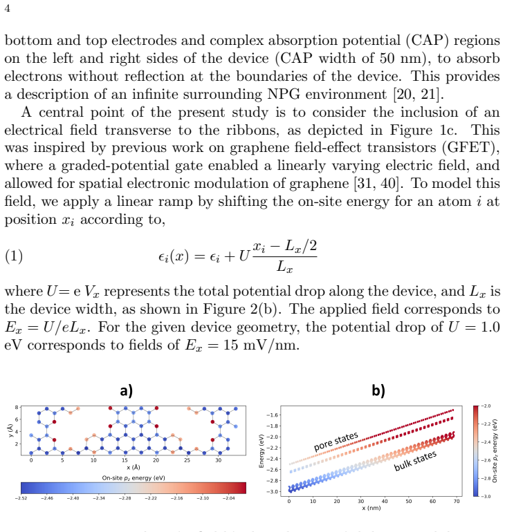
The argument rests on the linear-ramp potential model of Eq. (1), which assumes the gate-induced potential drops strictly linearly across the whole device; the DFT validation shows linearity only in the middle of a small, strongly fringed test cell, so a real gate with a nonlinear drop would distort or destroy the predicted periodic revival and single-ribbon localization.
Editorial extensions
If this is right
- The current refocuses with a Bloch period $Z_T = 2\pi/\Delta$ that shrinks as the field grows, so the device works as a voltage-tunable spatial oscillator.
- At high fields the same mechanism pins the injected current to its original ribbon, giving an electrical switch between delocalized and single-ribbon flow.
- The revival distance can be predicted from a DFT band slope without free parameters, so transport maps and band structure are directly linked.
- Vacancy disorder at concentrations up to about 0.1% perturbs but does not destroy the periodic revival, making the effect plausible in real samples.
- Electrostatic gating changes the band slope and inter-ribbon coupling and therefore tunes the Bloch period, giving two independent electrical control knobs.
Reading between the lines
- The same DDE and Bessel solution should describe any weakly coupled one-dimensional waveguide array with a linear gradient, so the mechanism is not specific to nanoporous graphene; the paper does not state this generalization.
- A time-modulated transverse field could turn the static breathing modes into a driven quantum walk, connecting to the quantum-information applications the conclusion gestures at but does not analyze.
- The faint high-field Landau-Zener leakage to bridge and pore states could be engineered as a molecular-scale beam splitter or energy filter, a design consequence the authors note but do not develop.
- If a scanning-gate measurement finds a nonlinear potential profile, the predicted $Z_T \propto 1/E_x$ dependence would fail in a characteristic, local-field-dependent way, marking where the linear-ramp model breaks.
Editorial analysis
A structured set of objections, weighed in public.
Referee Report
Summary. The manuscript studies point-injected electron transport in nanoporous graphene under a transverse electric field. Using a DFT-pruned tight-binding Hamiltonian and large-scale NEGF transport simulations, the authors observe that the injected current refocuses periodically along the ribbons at low fields and becomes localized to a single ribbon at high fields, which they interpret as spatial Bloch oscillations/breathing modes. They introduce a discrete differential equation (DDE) model of coupled GNR waveguides with a Bessel-function solution, predict a revival length Z_T = 2π/Δ (Eq. 7), and compare the DDE intensity maps with the transport simulations. The paper also reports a disorder-robustness study based on random carbon vacancies.
Significance. If the main claims hold, the paper demonstrates a simple electrical mechanism for controlling current flow at the molecular scale in a synthesized 2D carbon lattice, with potential relevance to nanoelectronics, sensing, and quantum walks. The combination of DFT-derived tight-binding Hamiltonians, large-scale NEGF transport, and a compact analytical waveguide model is attractive, and the disorder tests address experimental feasibility. However, the quantitative predictive power is currently weakened by a dimensional inconsistency in the printed analytical solution (Eq. 6), by the use of an effective band slope fitted to the very large-scale data it is used to predict (SM 9.1), and by the limited validation of the linear-ramp field model (Sec. 2.2, Fig. 3). These issues are fixable but need to be addressed before the quantitative claims can be accepted.
major comments (4)
- [Sec. 4, Eq. (6)] Equation (6) does not solve Eq. (5) as written. Since κ and Δ both have units of inverse length and α = Δ/κ is dimensionless, the argument α y/2 in the Bessel function and the phase α y have units of length; the correct solution for Eq. (5) should involve Δ y (equivalently κ y), e.g., up to a gauge/index convention, ψ_n(y) ∝ J_n(4κ/Δ sin(Δ y/2)) exp(iΔ n y/2). With the fitted κ = 0.01 Å^{-1}, the printed Eq. (6) produces oscillations on a length scale roughly 100 times too short, so it cannot be the solution used for the lower panels of Fig. 4. Please correct Eq. (6), state the gauge and initial-condition conventions, and rerun the DDE comparison.
- [SM 9.1 and Fig. 6] The effective band slope s_eff = 3.23 eV Å is obtained by fitting the large-scale computed Z_T versus N_x curve (SM Fig. 6a) and is then used to 'predict' the same Z_T data and the DDE maps in Fig. 4. This is a consistency check, not an independent prediction. The DFT-derived s_avg = 3.49 eV Å is the genuine ab initio input; the authors should present the s_avg-based comparison as the principal test and clearly label s_eff as a fitting parameter, with a statement of how much of the reported agreement depends on that fit.
- [Sec. 2.2, Eq. (1), and Fig. 3] The linear-ramp model is load-bearing for the central claim, because both the large-scale transport and the DDE assume a strictly linear transverse potential. The DFT validation is performed on a small 8-GNR, hydrogen-passivated double-gate cell with exaggerated fields, and the text itself states that the potential shows a 'modulated drop' with linearity only 'in the middle of the structure'. Screening by the NPG charge carriers and the different device-scale gate geometry are not addressed. The authors should either provide a self-consistent electrostatic calculation at device scale or explicitly state that the predictions assume an idealized linear ramp and discuss how deviations would affect Z_T and the localization pattern.
- [Sec. 5 and Fig. 5] The robustness claim is based on a single disorder realization per vacancy concentration. With random vacancies, transport maps can fluctuate strongly from sample to sample; the conclusion that the Bloch period revival is preserved at 0.1% disorder should be supported by configurational averaging or at least by several independent realizations with a measure of spread.
minor comments (5)
- [Abstract and Sec. 5] There are typos in the abstract ('apporx') and in Sec. 5 ('ocillation'), and Eq. (3) has a doubled closing bracket.
- [Fig. 1 caption, Sec. 2.1, Fig. 3] The gate distance is given as 15 nm in the Fig. 1 caption but as 15 Å in Sec. 2.1 and Fig. 3; please unify the values.
- [Sec. 2.2] The statement that the results are 'general for both double and single gate devices' is not supported by the presented calculations; please qualify or justify it.
- [Eq. (9)] The notation in Eq. (9) with the inline 'avg =|dE_n/dk|_E' fragment is unclear; define the average explicitly and avoid the fragment.
- [Fig. 4 caption and Sec. 4] The caption states that the DDE initial intensity is chosen to reproduce the observed bond currents; this fitting should also be stated in the main text when the DDE is said to 'reproduce' the large-scale maps.
Circularity Check
Partial circularity: the DDE revival period is calibrated with an effective band slope fitted to the same LS Z_T data it then reproduces, and the DDE initial amplitude is matched to the observed bond-current maps; the breathing-mode phenomenon itself is independently present in the LS simulations.
-
fitted input called prediction
[SM Sec. 9.1, Eqs. (9)-(10), Fig. 6; main text Sec. 4]
"This allowed us to parametrized an effective band-slope s_eff = 3.23 eV Å... We used this effective band-slope to calculate Δ and obtained a parameterized DDE that describes the Z_T observed in the Bloch oscillations (Fig.6b). We observed excellent agreement between the DDE parameterized with s_eff (dashed black line) and the LS results (red dots)."
Main text Sec. 4 says the parameters are 'extracted from the DFT calculations' and that s_eff gave excellent agreement for the oscillation period. SM 9.1 reveals that s_eff was instead obtained by fitting Z_T versus N_x from the same LS simulations whose periods the DDE then reproduces. Inserting this fitted s_eff into Delta (Eq. 9) and Z_T = 2*pi/Delta (Eq. 7/10) makes the Fig. 6b dashed line pass through the calibrated period, so the period normalization agreement is partly a restatement of the fit. The DFT-derived s_av = 3.49 eV Å provides independent order-of-magnitude support, so the circularity is partial rather than total.
-
fitted input called prediction
[Fig. 4 caption; main text Sec. 4]
"In the DDE, the initial intensity |ψ(z0)|2 is such to reproduce the observed bond currents."
The DDE spatial maps in Fig. 4 are compared with LS maps after choosing the DDE initial amplitude to match the same bond-current data, so the absolute intensity distribution in the lower DDE panels is fitted rather than predicted. The periodic revival and field-dependent localization are intrinsic to the DDE solution, so this is a secondary fitting of initial conditions that does not by itself create the breathing-mode effect.
full rationale
The paper's central phenomenon is not circular: the LS TB transport simulations (Sec. 2.3, Fig. 4) directly show field-dependent periodic refocusing and single-ribbon localization under the applied ramp of Eq. (1), and the analytical DDE (Eq. 5) with solution (Eq. 6) is an external waveguide-array result (Peschel et al. [5]) applied to this system. The DFT-derived band slope s_av = 3.49 eV Å gives the correct order of magnitude for the revival period, providing independent grounding. The partial circularity lies in Sec. 4/SM 9.1: the 'excellent agreement' for the period uses s_eff = 3.23 eV Å, which was obtained by fitting the same LS Z_T-versus-N_x data that the DDE then reproduces, while the main text presents the parameters as 'extracted from the DFT calculations.' Similarly, the DDE initial intensity is chosen to match the observed bond currents (Fig. 4 caption), so the absolute DDE intensity comparison is fitted, although the periodicity and localization are intrinsic to the DDE solution. The linear-ramp assumption of Eq. (1) is a physical modeling assumption; the DFT test cell's 'modulated drop' is an independent check, not an input that forces the LS ramp, so any device-scale validity concern is a correctness risk rather than a circularity. No load-bearing self-citation chain or imported uniqueness theorem was found, and the main breathing-mode claim has independent computational content; the fitted parameters affect the quantitative period and absolute DDE intensity, not the existence of the effect.
Assumptions & free parameters
free parameters (3)
- effective band slope s_eff =
3.23 eV Å
- inter-ribbon coupling κ =
0.01 1/Å
- DDE initial amplitude |ψ(z0)|^2 =
adjusted to reproduce bond currents
assumptions (4)
- domain assumption A transverse electric field is modeled as a linear ramp of the p_z on-site energies (Eq. 1).
- domain assumption NPG is modeled as an effective 1D array of weakly coupled waveguides with linear dispersion (Section 4).
- domain assumption The p_z-only pruned Hamiltonian reproduces DFT band structure for transport (Fig. 1b).
- standard math The atomic point contact is described by a self-energy term in the Green's function (Ref. [20]).
Cite this review
Pith. "Pith review of Field-controlled Electronic Breathing Modes and Transport in Nanoporous Graphene." pith.science (2026). https://pith.science/paper/5O3BWZP5
@misc{pith2026250604966,
  author       = {Pith},
  title        = {Pith review of: Field-controlled Electronic Breathing Modes and Transport in Nanoporous Graphene},
  year         = {2026},
  howpublished = {\url{https://pith.science/paper/5O3BWZP5}},
  note         = {Machine review of arXiv:2506.04966}
}
read the original abstract
Nanoporous graphene (NPG) has been fabricated by on-surface-self assembly in the form of arrays of apporx. 1 nm-wide graphene nanoribbons connected via molecular bridges in a two-dimensional crystal lattice. It is predicted that NPG may, despite its molecular structure, work as electron waveguides that display e.g. Talbot wave interference. Here, we demonstrate how the electronic wave guidance may be controlled by the use of electrical fields transverse to the ribbons; at low fields, point injected currents display spatially periodic patterns along the ribbons, while high fields localize the injected current to single ribbons. This behavior constitutes an electronic version of optical breathing modes of Bloch oscillations, providing a simple mechanism for controlling the current patterns down to the molecular scale. The robustness of the self-repeating patterns under disorder demonstrate that the breathing modes of single-ribbon injections offer exciting opportunities for applications in nanoelectronics, molecular sensing, and quantum information processing.
Figures


Figures from the paper (4 more)


Reference graph
Works this paper leans on
-
[1]
Calogero, G., Papior, N., Kretz, B., Garcia-Lekue, A., Frederiksen, T. & Brandbyge, M. Electron Transport in Nanoporous Graphene: Probing the Talbot Effect.Nano Letters.19, 576-581 (2019)
work page 2019
-
[2]
Moreno, C., Vilas-Varela, M., Kretz, B., Garcia-Lekue, A., Costache, M., Paradinas, M., Panighel, M., Ceballos, G., Valenzuela, S., Pe˜ na, D. & Aitor Mugarza Bottom-up synthesis of multifunctional nanoporous graphene.Science.360, 199-203 (2018)
work page 2018
-
[3]
Calogero, G., Alc´ on, I., Papior, N., Jauho, A. & Brandbyge, M. Quantum Interfer- ence Engineering of Nanoporous Graphene for Carbon Nanocircuitry.Journal Of The American Chemical Society.141, 13081-13088 (2019), PMID: 31342738
work page 2019
-
[4]
Tenorio, M., Moreno, C., Febrer, P., Castro-Esteban, J., Ordej´ on, P., Pe˜ na, D., Pruneda, M. & Mugarza, A. Atomically Sharp Lateral Superlattice Heterojunctions Built-In Nitrogen-Doped Nanoporous Graphene.Advanced Materials.34, 2110099 (2022)
work page 2022
-
[5]
Peschel, U., Pertsch, T. & Lederer, F. Optical Bloch oscillations in waveguide arrays. Opt. Lett..23, 1701-1703 (1998,11)
work page 1998
- [6]
-
[7]
Iwanow, R., May-Arrioja, D., Christodoulides, D., Stegeman, G., Min, Y. & Sohler, W. Discrete Talbot effect in waveguide arrays..Physical Review Letters.95 5pp. 053902 (2005)
work page 2005
- [8]
Show all 41 references
-
[9]
& Brandbyge, M
Alc´ on, I., Calogero, G., Papior, N. & Brandbyge, M. Electrochemical Control of Charge Current Flow in Nanoporous Graphene.Advanced Functional Materials.31, 2104031 (2021)
2021
-
[10]
& Zehnl´ e, V
Thommen, Q., Garreau, J. & Zehnl´ e, V. Quantum interference in a driven washboard potential.American Journal Of Physics.72, 1017-1025 (2004,8)
2004
-
[11]
& Dum´ ee, L
Guirguis, A., Maina, J., Zhang, X., Henderson, L., Kong, L., Shon, H. & Dum´ ee, L. Applications of nano-porous graphene materials – critical review on performance and challenges.Mater. Horiz..7, 1218-1245 (2020)
2020
-
[12]
& Wang, X
Wang, H., Wang, H., Ma, C., Chen, L., Jiang, C., Chen, C., Xie, X., Li, A. & Wang, X. Graphene nanoribbons for quantum electronics.Nature Reviews Physics. 3, 791-802 (2021,12)
2021
-
[13]
¨Uber die Quantenmechanik der Elektronen in Kristallgittern.Zeitschrift F¨ ur Physik.52, 555-600 (1929,7)
Bloch, F. ¨Uber die Quantenmechanik der Elektronen in Kristallgittern.Zeitschrift F¨ ur Physik.52, 555-600 (1929,7)
1929
-
[14]
& Stokbro, K
Brandbyge, M., Mozos, J., Ordej´ on, P., Taylor, J. & Stokbro, K. Density-functional method for nonequilibrium electron transport.Phys. Rev. B.65, 165401 (2002,3)
2002
-
[15]
Nanoscale device modeling: the Green’s function method.Superlattices And Microstructures.28pp
Datta, S. Nanoscale device modeling: the Green’s function method.Superlattices And Microstructures.28pp. 253-278 (2000)
2000
-
[16]
& S´ anchez- Portal, D
Soler, J., Artacho, E., Gale, J., Garc ´ ıa, A., Junquera, J., Ordej´ on, P. & S´ anchez- Portal, D. The SIESTA method for ab initio order-N materials simulation.Journal Of Physics: Condensed Matter.14pp. 2745 - 2779 (2001)
2001
-
[17]
& Brandbyge, M
Papior, N., Lorente, N., Frederiksen, T., Garc ´ ıa, A. & Brandbyge, M. Improvements on non-equilibrium and transport Green function techniques: The next-generation transiesta.Computer Physics Communications.212pp. 8-24 (2017)
2017
-
[18]
sisl: v0.15.2
Papior, N. sisl: v0.15.2. (2024) 13
2024
-
[19]
& Brandbyge, M
Papior, N., Gunst, T., Stradi, D. & Brandbyge, M. Manipulating the voltage drop in graphene nanojunctions using a gate potential.Phys. Chem. Chem. Phys..18, 1025-1031 (2016)
2016
-
[20]
& Brandbyge, M
Calogero, G., Papior, N., Bøggild, P. & Brandbyge, M. Large-scale tight-binding sim- ulations of quantum transport in ballistic graphene.Journal Of Physics: Condensed Matter.30, 364001 (2018,8)
2018
-
[21]
& Chen, G
Xie, H., Kwok, Y., Jiang, F., Zheng, X. & Chen, G. Complex absorbing potential based Lorentzian fitting scheme and time dependent quantum transport.The Journal Of Chemical Physics.141, 164122 (2014,10)
2014
-
[22]
& Ott, H
Santra, B., Baals, C., Labouvie, R., Bhattacherjee, A., Pelster, A. & Ott, H. Mea- suring finite-range phase coherence in an optical lattice using Talbot interferometry. Nature Communications.8, 15601 (2017,6)
2017
-
[23]
& Xiao, M
Wen, J., Zhang, Y. & Xiao, M. The Talbot effect: recent advances in classical optics, nonlinear optics, and quantum optics.Adv. Opt. Photon..5, 83-130 (2013,3)
2013
-
[24]
& Markus Greiner Strongly correlated quantum walks in optical lattices.Science
Preiss, P., Ma, R., Tai, M., Lukin, A., Rispoli, M., Zupancic, P., Lahini, Y., Islam, R. & Markus Greiner Strongly correlated quantum walks in optical lattices.Science. 347, 1229-1233 (2015)
2015
-
[25]
Photonic Crystal Design through Talbot Effect.12th International Confer- ence On Fiber Optics And Photonics
Negi, R. Photonic Crystal Design through Talbot Effect.12th International Confer- ence On Fiber Optics And Photonics. pp. S5A.86 (2014)
2014
-
[26]
& Fowler, R
Zener, C. & Fowler, R. A theory of the electrical breakdown of solid dielectrics. Proceedings Of The Royal Society Of London. Series A, Containing Papers Of A Mathematical And Physical Character.145, 523-529 (1934)
1934
-
[27]
& Paris, M
Tamascelli, D., Olivares, S., Rossotti, S., Osellame, R. & Paris, M. Quantum state transfer via Bloch oscillations.Scientific Reports.6, 26054 (2016,5)
2016
-
[28]
& Fabian, J
Han, W., Kawakami, R., Gmitra, M. & Fabian, J. Graphene spintronics.Nature Nanotechnology.9, 794-807 (2014,10)
2014
-
[29]
& Roche, S
Alc´ on, I., Cummings, A. & Roche, S. Tailoring giant quantum transport anisotropy in nanoporous graphenes under electrostatic disorder.Nanoscale Horiz..9, 407-415 (2024)
2024
-
[30]
& Cummings, A
Antidormi, A. & Cummings, A. All-carbon approach to inducing electrical and optical anisotropy in graphene.AIP Advances.11, 115007 (2021,11)
2021
-
[31]
& Qiu, X
Wang, X., Jiang, X., Wang, T., Shi, J., Liu, M., Zeng, Q., Cheng, Z. & Qiu, X. Electrically Configurable Graphene Field-Effect Transistors with a Graded-Potential Gate.Nano Letters.15, 3212-3216 (2015,5)
2015
-
[32]
& Zagury, N
Aharonov, Y., Davidovich, L. & Zagury, N. Quantum random walks.Phys. Rev. A. 48, 1687-1690 (1993,8)
1993
-
[33]
& Mugarza, A
Moreno, C., Cerio, X., Vilas-Varela, M., Tenorio, M., Sarasola, A., Brandbyge, M., Pena, D., Garcia-Lekue, A. & Mugarza, A. Molecular Bridge Engineering for Tuning Quantum Electronic Transport and Anisotropy in Nanoporous Graphene.J. Am. Chem. Soc..145, 8988-8995 (2023)
2023
-
[34]
& Ratner, M
Solomon, G., Herrmann, C., Hansen, T., Mujica, V. & Ratner, M. Exploring local currents in molecular junctions.Nat. Chem..2, 223-228 (2010,3)
2010
-
[35]
& Tsukada, M
Nakanishi, S. & Tsukada, M. Quantum Loop Current in a C60 Molecular Bridge. Physical Review Letters.87, 126801 (2001)
2001
-
[36]
& Ernzerhof, M
Perdew, J., Burke, K. & Ernzerhof, M. Generalized Gradient Approximation Made Simple.Phys. Rev. Lett..77, 3865-3868 (1996,10)
1996
-
[37]
& Ishigami, M
Chen, J., Jang, C., Adam, S., Fuhrer, M., Williams, E. & Ishigami, M. Charged- impurity scattering in graphene.Nature Physics.4, 377-381 (2008,5)
2008
-
[38]
& Garcia-Lekue, A
Cerio, X., Bach Lorentzen, A., Brandbyge, M. & Garcia-Lekue, A. Twisting nanoporous graphene on graphene: electronic decoupling and chiral currents.Nano Letters.25, 1281-1286 (2025) 14
2025
-
[39]
& Iv´ an Brihuega Atomic-scale control of graphene magnetism by using hydrogen atoms.Science.352, 437-441 (2016)
Gonz´ alez-Herrero, H., G´ omez-Rodr ´ ıguez, J., Mallet, P., Moaied, M., Palacios, J., Salgado, C., Ugeda, M., Veuillen, J., Yndurain, F. & Iv´ an Brihuega Atomic-scale control of graphene magnetism by using hydrogen atoms.Science.352, 437-441 (2016)
2016
-
[40]
Lassaline, N. Generating smooth potential landscapes with thermal scanning-probe lithography.Journal Of Physics: Materials.7, 015008 (2023,11) 15 9.Supplementary Material 9.1.Fitting of DDE model.Previously [1], it was found that the inter- ribon coupling (κ) can be obtained f...
2023
-
[41]
Complex scattering takes place and the Bloch oscillations are not present for non-zero fields
For a gate ofg=−0.2 only the lowest band is available at theE F and is approximately parabolic. Complex scattering takes place and the Bloch oscillations are not present for non-zero fields. Atg=−0.5 both bands present propagating states atE F around the injecting ribbon. Here...
Reviewed August 7, 2026 · model on record in the stance chip above.
Discussion (0). Continue with ORCID to comment.