REVIEW 1 major objections 1 minor
Energetic coupling between field dislocation mechanics and phase field crystal ignores the incompatible distortion encoding dislocation topology.
Reviewed by Pith at T0; open to challenge. T0 means a machine referee read the full paper against a public rubric. the ladder, T0–T4 →
T0 review · grok-4.3
2026-07-03 19:53 UTC pith:7UCEBIRK
load-bearing objection L2 coupling between FDM and PFC only affects compatible distortions and stays blind to dislocation topology even in general energetic cases. the 1 major comments →
On the limits of the energetic coupling between field dislocation mechanics and phase field crystal
The pith
A machine-rendered reading of the paper's core claim, the machinery that carries it, and where it could break.
Core claim
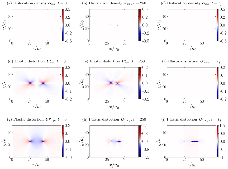
Variational analysis shows that the coupling term in the phase-field evolution equation is divergence-driven and matches only the compatible (curl-free) parts of the distortion fields from FDM and PFC. Its contributions are therefore insensitive to the incompatible (divergence-free) elastic distortion that contains all information on dislocation topology. The configurational nature of the PFC distortion further implies that mechanical boundary conditions are transmitted diffusively from FDM to PFC. Numerical simulations confirm that this coupling cannot prevent the unnatural core spreading in FDM, and the same drawbacks apply to any energetic coupling.
What carries the argument
L2 penalization of the difference between FDM elastic distortion and PFC configurational distortion, whose variational derivative produces a divergence-driven forcing term.
Load-bearing premise
The coupling energy is constructed as an L2 penalization between the FDM elastic distortion and the PFC configurational distortion, leading to a purely divergence-driven variational derivative.
What would settle it
A calculation or simulation where only the incompatible part of the FDM distortion is changed while the compatible part is held fixed, to check if the PFC phase field evolution remains unaffected.
If this is right
- The coupling term is insensitive to incompatible distortion carrying dislocation topology.
- Mechanical boundary conditions transmit diffusively rather than elastically.
- The coupling cannot prevent unnatural core spreading in FDM.
- These limitations persist in the most general energetic coupling.
Where Pith is reading between the lines
- Direct coupling to incompatibility measures or curl components may be required to link dislocation topology.
- Non-energetic or hybrid coupling strategies might overcome the diffusive transmission issue.
- Similar limitations could affect other multi-scale models that rely on energy penalties between continuum and atomistic fields.
Editorial analysis
A structured set of objections, weighed in public.
Referee Report
Summary. The manuscript analyzes the energetic coupling between Field Dislocation Mechanics (FDM) and the Phase Field Crystal (PFC) model, originally proposed via an L² penalization between the FDM elastic distortion and PFC configurational distortion. Variational calculus shows that this term produces only divergence-driven forcing in the PFC evolution equation, coupling exclusively to the compatible (curl-free) distortion components while remaining insensitive to the incompatible (divergence-free) part that encodes dislocation topology. The analysis further concludes that mechanical boundary conditions are transmitted diffusively rather than elastically, that numerical simulations confirm the coupling cannot suppress unnatural core spreading in FDM, and that these limitations persist for arbitrary energetic couplings.
Significance. If the variational results and the extension to the general energetic case are rigorously established, the work provides a clear diagnostic of fundamental limitations in L²-style couplings for reconciling continuum dislocation mechanics with crystallographic models. This could usefully constrain future multiscale modeling efforts in materials science by highlighting the need for couplings that directly engage incompatible distortion fields.
major comments (1)
- [Abstract] Abstract (general-case claim): the assertion that 'even in the most general case, an energetic coupling suffers from the same drawbacks' is load-bearing for the central conclusion, yet the provided variational analysis is constructed around the specific L² inner-product penalization; an explicit derivation for arbitrary energetic functionals (without tacit retention of the L² structure or the assumption that the PFC distortion remains curl-free) is required to substantiate the extrapolation.
minor comments (1)
- The description of the numerical simulations omits quantitative error measures, convergence data, or explicit statements of boundary conditions, which would allow direct assessment of the core-spreading claim.
Simulated Author's Rebuttal
We thank the referee for the careful review and constructive feedback. We address the single major comment below.
read point-by-point responses
-
Referee: [Abstract] Abstract (general-case claim): the assertion that 'even in the most general case, an energetic coupling suffers from the same drawbacks' is load-bearing for the central conclusion, yet the provided variational analysis is constructed around the specific L² inner-product penalization; an explicit derivation for arbitrary energetic functionals (without tacit retention of the L² structure or the assumption that the PFC distortion remains curl-free) is required to substantiate the extrapolation.
Authors: We acknowledge that the explicit variational calculations are performed for the L² penalization. The general-case statement rests on the structural observation that any local energetic coupling of the form ∫ F(β^FDM − β^PFC) dV produces, upon variation with respect to β^PFC, a forcing term whose leading contribution is the divergence of a tensor obtained from the functional derivative of F. Consequently the PFC evolution equation remains insensitive to the curl-free projection of the distortion difference, independent of the specific form of F. The curl-free character of β^PFC follows directly from its construction within the PFC model (as the symmetrized gradient of the phase field). To make this argument fully rigorous and remove any tacit reliance on the L² structure, we will insert an explicit derivation for a general differentiable functional F in a new subsection of the revised manuscript. revision: yes
Circularity Check
No significant circularity; direct variational analysis of stated energy functional
full rationale
The paper applies standard variational calculus to the L2 penalization energy between FDM elastic distortion and PFC configurational distortion (as defined in the 2020 reference being critiqued). The insensitivity to incompatible distortion follows from the divergence structure of the resulting Euler-Lagrange terms, and the general-case extension uses the same structure without introducing fitted parameters, self-referential uniqueness theorems, or ansatzes smuggled via citation. The 2020 citation supplies the object of analysis rather than load-bearing justification for the result. No step reduces the claimed prediction to an input by construction.
Axiom & Free-Parameter Ledger
axioms (2)
- standard math Variational calculus yields the correct evolution equations from the total energy functional that includes the L2 coupling term
- domain assumption The configurational distortion field in the PFC model is of a form whose curl-free part can be directly compared to the FDM elastic distortion
read the original abstract
This paper investigates the energetic coupling between Field Dislocation Mechanics (FDM) and the Phase Field Crystal (PFC) model proposed in Phys. Rev. B 102, 064109, 2020. While FDM correctly solves the initial boundary value problem of a continuum body with dislocation fields, PFC captures the underlying crystallographic structure. The coupling, which penalizes the $L^2$ distance between elastic distortion from FDM and configurational distortion from PFC in the $L^2$ sense, had been proposed to reconcile dislocation mechanics with crystallography in a single continuum framework. Variational analysis reveals that the coupling term acts as a divergence-driven forcing in the phase-field evolution that matches only the compatible (curl-free) parts of the distortion fields. Consequently, its contributions are insensitive to the incompatible (divergence-free) elastic distortion carrying all the information on dislocation topology. Furthermore, the nature of the configurational distortion causes mechanical boundary conditions to be transmitted diffusively from FDM to PFC rather than elastically. Numerical simulations demonstrate that this coupling cannot prevent the unnatural core spreading in FDM. Finally, it is shown that even in the most general case, an energetic coupling suffers from the same drawbacks, which limits its ability to integrate dislocation mechanics with crystallography.
Figures




discussion (0)
Sign in with ORCID, Apple, or X to comment. Anyone can read and Pith papers without signing in.