REVIEW 2 major objections 6 minor 39 references
Energetic L2 coupling of field dislocation mechanics to the phase-field crystal only matches compatible distortions, is blind to dislocation topology, and cannot stop unnatural core spreading.
Reviewed by Pith at T0; open to challenge. T0 means a machine referee read the full paper against a public rubric. the ladder, T0–T4 →
T0 review · grok-4.5
2026-07-12 09:21 UTC pith:7UCEBIRK
load-bearing objection Solid negative result: the Acharya–Viñals L2 (and p-norm) energetic penalty only forces compatible mismatch, so it cannot reconcile FDM cores with PFC crystallography. the 2 major comments →
On the limits of the energetic coupling between field dislocation mechanics and phase field crystal
The pith
A machine-rendered reading of the paper's core claim, the machinery that carries it, and where it could break.
Core claim
The L2 energetic penalty between elastic distortion from field dislocation mechanics and configurational distortion from the phase-field crystal produces only a divergence-driven forcing in the phase-field evolution. That forcing matches solely the compatible (curl-free) parts of the two fields and is insensitive to the incompatible (divergence-free) elastic distortion that carries dislocation topology. Mechanical boundary conditions are transmitted by phase diffusion rather than elasticity, the coupling cannot prevent unnatural core spreading, and the same drawbacks persist for any p-norm energetic coupling.
What carries the argument
The functional derivative of the L2 penalty with respect to the phase-field order parameter, which reduces to a forcing proportional to the divergence of the difference between configurational and elastic distortions and therefore annihilates all incompatible content.
Load-bearing premise
The claim that only the divergence of the distortion mismatch enters the phase-field forcing rests on representing configurational distortion through slowly varying complex amplitudes obtained by Gaussian demodulation of the order parameter.
What would settle it
Deliberately mismatch the incompatible parts of the two distortion fields while keeping their divergences equal, then evolve under the penalty alone: if the phase field still equalizes the incompatible parts or suppresses field-dislocation-mechanics core spreading, the central claim fails.
If this is right
- Any pure energetic mismatch of the two distortion fields leaves the two dislocation densities free to evolve independently.
- Boundary loads reach the phase-field crystal only by phase diffusion, never by instantaneous elastic relaxation.
- Core localization cannot be imported from the phase-field crystal into field dislocation mechanics by an energetic penalty of this type alone.
- A phase-field-crystal-driven plastic flux can keep a single dislocation density but does not guarantee non-negative plastic dissipation.
- Integrating continuum dislocation mechanics with crystallography requires couplings beyond pure energy penalties on distortion mismatch.
Where Pith is reading between the lines
- Kinematic constraints that directly identify the two dislocation densities, rather than energetic penalties on their parent distortions, may be needed to transfer topology between the models.
- The same divergence-only limitation would appear in any continuum scheme that couples two distortion fields solely through an L2 or p-norm energy of their difference when one field is reconstructed from demodulated complex amplitudes.
- The empty window between the minimum coupling needed for fast penalty relaxation and the maximum that avoids pinning suggests parameter tuning alone cannot rescue the present construction.
Editorial analysis
A structured set of objections, weighed in public.
Referee Report
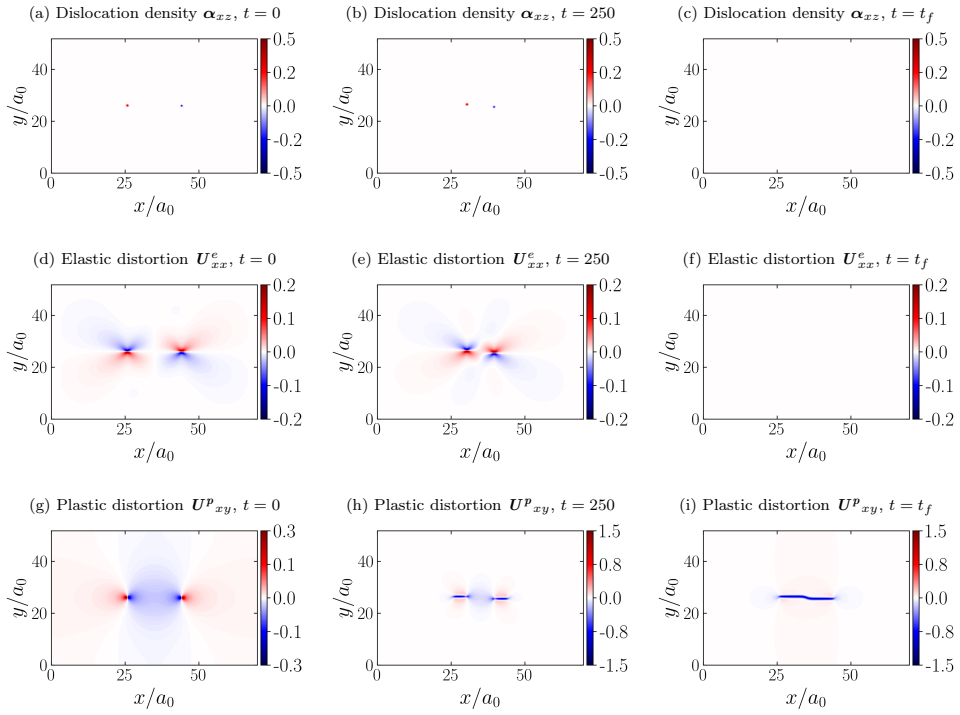
Summary. The manuscript analyzes the energetic L2 penalty coupling between Field Dislocation Mechanics (FDM) elastic distortion Ue and Phase Field Crystal (PFC) configurational distortion Q proposed by Acharya and Viñals (Phys. Rev. B 102, 064109, 2020). Through a variational calculation of δFpen/δψ (Appendix B, Eqs. 31–37 and 52–67), it shows that the bulk forcing depends only on ∇·(Q−Ue) and therefore matches only the compatible parts of the two distortions, remaining blind to the incompatible, dislocation-carrying parts. The same structure implies that mechanical boundary data are transmitted by phase diffusion of the complex amplitudes rather than by elastic relaxation (Eqs. 39–41), and that a residual incompatible mismatch can persist at equilibrium (Stokes–Helmholtz argument, Eq. 38). The analysis is extended to a family of p-norm penalties (Eqs. 44–46), which retain the same divergence-driven character. Numerical experiments on an immobile dipole, free-core evolution, and dipole annihilation under both FDM-driven and PFC-driven plasticity confirm dual dislocation densities, residual core spreading, an empty operating window for the coupling strength cpen, and (in the PFC-driven case) non-positive plastic dissipation.
Significance. The paper supplies a clear, structural negative result on a coupling that was proposed as a thermodynamically consistent route to combine crystallography with continuum dislocation mechanics. The central variational reduction (forcing depends only on ∇·(Q−Ue)) is clean, independent of the particular inverse map from amplitudes to ψ, and is corroborated by independent numerical tests that exhibit dual densities, core spreading, and dissipation issues. The empty cpen window (Section 6.1) and the regularity/log-divergence observation (Section 4.3) are useful quantitative diagnostics for anyone attempting related couplings. If the conclusions hold, they usefully delimit the domain of applicability of pure energetic mismatch penalties between Ue and Q and redirect the community toward alternative (e.g., kinematic or mixed) couplings. The work is therefore of genuine interest to the dislocation-mechanics and phase-field communities.
major comments (2)
- Abstract and final sentence of the conclusion state that “even in the most general case, an energetic coupling suffers from the same drawbacks.” Section 4.4 only treats the one-parameter family fpen = (1/(2p))[(Ue−Q):A:(Ue−Q)]p and shows that the functional derivative retains a divergence structure (Eq. 45). That is not the most general energetic coupling (for example, penalties involving curls of the distortions, or direct penalties on α−eα, are not covered). The claim should be narrowed to “general p-norm penalties of the distortion mismatch” so that the abstract matches the derivation that is actually given.
- Section 6.2 and Eq. (30): the demonstration that plastic dissipation ∫σ:Jψ can be negative is numerical and configuration-specific (dipole annihilation). The structural argument that no consistent evolution for ψ̇ can guarantee positivity when Jψ is taken from the amplitudes alone is stated but not proved for general loadings. A short analytic counter-example or a clearer statement of the scope of the negativity claim would strengthen the load-bearing conclusion that the PFC-driven route is thermodynamically flawed.
minor comments (6)
- Figure 1 caption: panels are listed as (a)–(e) but the text refers to (b) dislocation density and (d) contour of the penalty forcing; the ordering of (c) and (e) is easy to misread. A single sentence clarifying the layout would help.
- Figure 7 caption: “v ,d” contains a stray space/comma; should be vd.
- Eq. (48) and the fit for Bref: the reference trajectory is obtained from uncoupled PFC (cpen=0). It would be useful to state explicitly in the main text (not only Appendix D) that the same Bref is then used for all coupled FDM-driven runs, so that the comparison is controlled.
- Reference [36] (Volterra) contains the typo “cirps” for “corps”; also several author names and titles could be checked for consistency with the published versions.
- Notation: both α and eα appear for the two dislocation densities; a brief reminder at the start of Section 5 that they are allowed to evolve independently under FDM-driven plasticity would reduce reader confusion.
- Section 3: the neglect of cross terms between ψ̇ and elastic stress is stated without citation to the original PFCFDM paper or a short justification; one sentence would suffice.
Circularity Check
No significant circularity: the paper critically analyzes a prior coupling via independent variational structure and numerics; self-citations supply the model under test, not the negative conclusions.
full rationale
This is a critical analysis of the Acharya–Viñals 2020 energetic coupling, not a derivation that re-packages its own inputs as predictions. The central negative claims (forcing depends only on ∇·(Q−Ue), blindness to incompatible/dislocation-carrying parts, phase-diffusive rather than elastic transmission of BCs, inability to prevent FDM core spreading, same structure for general p-norms, and non-positive plastic dissipation under PFC-driven plasticity) follow from the variational derivative of the published free-energy penalty (Eqs. 31–37, 45) together with independent numerical experiments (immobile dipole, free-core evolution, FDM- vs PFC-driven annihilation). Self-citations to Acharya–Viñals 2020 and Upadhyay–Viñals 2024 define the model being tested and supply background on the mismatch between Q and Ue; they are not used as uniqueness theorems or load-bearing external facts that force the paper’s conclusions. The amplitude demodulation and small-deformation Q formula are standard PFC machinery, and the paper notes that the divergence-only structure is independent of the particular inverse map. No fitted parameter is renamed a prediction, no ansatz is smuggled in via self-citation, and no known empirical pattern is merely renamed. Score 1 reflects only the ordinary presence of self-citations that are not load-bearing for the negative result.
Axiom & Free-Parameter Ledger
free parameters (5)
- c_pen (penalty coupling strength)
- c_sh (Swift–Hohenberg energy weight)
- B (dislocation drag / inverse mobility)
- r (PFC quench depth) and average ψ̄
- Gaussian mollifier widths (a0 for demodulation; a0/4 for Q smoothing)
axioms (6)
- domain assumption Small-strain FDM kinematics: ∇u = Ue + Up, α = ∇×Ue = −∇×Up, Stokes–Helmholtz split of Up, and mechanical equilibrium ∇·σ=0.
- domain assumption PFC free energy is the Swift–Hohenberg functional and ψ evolves by nonconserved gradient flow (with fixed average), not conserved H−1 dynamics.
- domain assumption Configurational distortion Q is defined from complex amplitudes via Q = −(d/N) Σ qn ⊗ Im(∇An/An), with An obtained by Gaussian demodulation of ψ.
- ad hoc to paper The Helmholtz free energy is Fel[Ue] + csh Fsh[ψ] + cpen (1/2)∥Ue−Q∥²_L2, and cross forces/currents between ψ and elastic stress are neglected.
- standard math Stokes–Helmholtz compatible and incompatible parts are L2-orthogonal, so matching divergences does not force matching curls.
- standard math For p-norm generalizations, the variational derivative still involves a divergence of a nonlinear function of (Ue−Q), hence the same phase-diffusion structure.
read the original abstract
This paper investigates the energetic coupling between Field Dislocation Mechanics (FDM) and the Phase Field Crystal (PFC) model proposed in Phys. Rev. B 102, 064109, 2020. While FDM correctly solves the initial boundary value problem of a continuum body with dislocation fields, PFC captures the underlying crystallographic structure. The coupling, which penalizes the $L^2$ distance between elastic distortion from FDM and configurational distortion from PFC in the $L^2$ sense, had been proposed to reconcile dislocation mechanics with crystallography in a single continuum framework. Variational analysis reveals that the coupling term acts as a divergence-driven forcing in the phase-field evolution that matches only the compatible (curl-free) parts of the distortion fields. Consequently, its contributions are insensitive to the incompatible (divergence-free) elastic distortion carrying all the information on dislocation topology. Furthermore, the nature of the configurational distortion causes mechanical boundary conditions to be transmitted diffusively from FDM to PFC rather than elastically. Numerical simulations demonstrate that this coupling cannot prevent the unnatural core spreading in FDM. Finally, it is shown that even in the most general case, an energetic coupling suffers from the same drawbacks, which limits its ability to integrate dislocation mechanics with crystallography.
Figures




Reference graph
Works this paper leans on
-
[1]
A. Acharya. A model of crystal plasticity based on the theory of continuously distributed dislo- cations. Journal of the Mechanics and Physics of Solids, 49(4):761–784, Apr. 2001
2001
-
[2]
A. Acharya. Microcanonical Entropy and Mesoscale Dislocation Mechanics and Plasticity.Journal of Elasticity, 104(1-2):23–44, Aug. 2011
2011
-
[3]
Acharya, L
A. Acharya, L. Angheluta, and J. Viñals. Elasticity versus phase field driven motion in the phase field crystal model.Modelling and Simulationin Materials Science and Engineering, 30(6):064005, Sept. 2022
2022
-
[4]
Acharya and A
A. Acharya and A. Roy. Size effects and idealized dislocation microstructure at small scales: Predictions of a Phenomenological model of Mesoscopic Field Dislocation Mechanics: Part I. Journal of the Mechanics and Physics of Solids, 54(8):1687–1710, Aug. 2006
2006
-
[5]
Acharya and J
A. Acharya and J. Viñals. Field dislocation mechanics and phase field crystal models.Physical Review B, 102(6):064109, Aug. 2020
2020
-
[6]
P. M. Anderson, J. P. Hirth, and J. Lothe.Theory of Dislocations. Cambridge University Press, Jan. 2017
2017
-
[7]
Arora, R
A. Arora, R. Arora, and A. Acharya. Mechanics of micropillar confined thin film plasticity.Acta Materialia, 238:118192, Oct. 2022
2022
-
[8]
R. Arora. Computational Approximation of Mesoscale Field Dislocation Mechanics at Finite Deformation. Thesis, Carnegie Mellon University, Mar. 2019
2019
-
[9]
Arora, X
R. Arora, X. Zhang, and A. Acharya. Finite element approximation of finite deformation dislo- cation mechanics. Computer Methods in Applied Mechanics and Engineering, 367:113076, Aug. 2020
2020
-
[10]
Berry, M
J. Berry, M. Grant, and K. R. Elder. Diffusive atomistic dynamics of edge dislocations in two dimensions. Physical Review E, 73(3):031609, Mar. 2006. 31
2006
-
[11]
Bradbury, R
J. Bradbury, R. Frostig, P. Hawkins, M. J. Johnson, C. Leary, D. Maclaurin, G. Necula, A. Paszke, J. VanderPlas, S. Wanderman-Milne, and Q. Zhang. JAX: Composable transformations of Python+NumPy programs, 2018
2018
-
[12]
P. Y. Chan, G. Tsekenis, J. Dantzig, K. A. Dahmen, and N. Goldenfeld. Plasticity and Dislocation Dynamics in a Phase Field Crystal Model.Physical Review Letters, 105(1):015502, June 2010
2010
-
[13]
S. M. Cox and P. C. Matthews. Exponential Time Differencing for Stiff Systems.Journal of Computational Physics, 176(2):430–455, Mar. 2002
2002
-
[14]
M. C. Cross and P. C. Hohenberg. Pattern formation outside of equilibrium.Reviews of modern physics, 65(3):851, 1993
1993
-
[15]
Devincre, V
B. Devincre, V. Pontikis, Y. Brechet, G. Canova, M. Condat, and L. Kubin. Three-Dimensional Simulations of Plastic Flow in Crystals. In M. Mareschal and B. L. Holian, editors,Microscopic Simulations of Complex Hydrodynamic Phenomena, pages 413–423. Springer US, Boston, MA, 1992
1992
-
[16]
K. R. Elder and M. Grant. Modeling elastic and plastic deformations in nonequilibrium processing using phase field crystals.Physical Review E, 70(5):051605, Nov. 2004
2004
-
[17]
K. R. Elder, M. Katakowski, M. Haataja, and M. Grant. Modeling Elasticity in Crystal Growth. Physical Review Letters, 88(24):245701, June 2002
2002
-
[18]
K. R. Elder, N. Provatas, J. Berry, P. Stefanovic, and M. Grant. Phase-field crystal modeling and classical density functional theory of freezing.Physical Review B, 75(6):064107, Feb. 2007
2007
-
[19]
Eymard, T
R. Eymard, T. Gallouët, and R. Herbin. Finite volume methods. In Solution of Equation in R (Part 3), Techniques of Scientific Computing (Part 3), volume 7 ofHandbook of Numerical Analysis, pages 713–1018. Elsevier, Jan. 2000
2000
-
[20]
StrongStabilityPreservingRunge-KuttaandMultistep Time Discretizations
S.Gottlieb, D.Ketcheson, andC.-W.Shu. StrongStabilityPreservingRunge-KuttaandMultistep Time Discretizations. WORLD SCIENTIFIC, 2011
2011
-
[21]
Halperin
B. Halperin. Physics of defects. In Physics of Defects, number XXXV in Proceedings of the Les Houches Summer School, pages 814–857. North Holland Publishing Company, r. balian, m. kleman, and j.-p. poirier edition, 1981
1981
-
[22]
Heinonen, C
V. Heinonen, C. V. Achim, J. M. Kosterlitz, S.-C. Ying, J. Lowengrub, and T. Ala-Nissila. Con- sistent Hydrodynamics for Phase Field Crystals. Physical Review Letters, 116(2):024303, Jan. 2016
2016
-
[23]
DYNAMICALTHEORYOFDISLOCATIONS
A.M.Kosevich. DYNAMICALTHEORYOFDISLOCATIONS. SovietPhysicsUspekhi, 7(6):837, June 1965
1965
-
[24]
G. F. Mazenko. Vortex Velocities in the $\mathit{O}(\mathit{n})$ Symmetric Time-Dependent Ginzburg-Landau Model. Physical Review Letters, 78(3):401–404, Jan. 1997
1997
-
[25]
T. Mura. Continuous distribution of moving dislocations.Philosophical Magazine, 8(89):843–857, May 1963
1963
-
[26]
A. Roy. Finite element approximation of field dislocation mechanics.Journal of the Mechanics and Physics of Solids, 53(1):143–170, Jan. 2005
2005
-
[27]
Skaugen, L
A. Skaugen, L. Angheluta, and J. Viñals. Dislocation dynamics and crystal plasticity in the phase-field crystal model.Physical Review B, 97(5):054113, Feb. 2018. 32
2018
-
[28]
Skaugen, L
A. Skaugen, L. Angheluta, and J. Viñals. Separation of Elastic and Plastic Timescales in a Phase Field Crystal Model.Physical Review Letters, 121(25):255501, Dec. 2018
2018
-
[29]
Skogvoll, L
V. Skogvoll, L. Angheluta, A. Skaugen, M. Salvalaglio, and J. Viñals. A phase field crystal theory of the kinematics of dislocation lines.Journal of the Mechanics and Physics of Solids, 166:104932, Sept. 2022
2022
-
[30]
Skogvoll, J
V. Skogvoll, J. Rønning, M. Salvalaglio, and L. Angheluta. A unified field theory of topological defects and non-linear local excitations.npj Computational Materials, 9(1):1–13, July 2023
2023
-
[31]
Skogvoll, M
V. Skogvoll, M. Salvalaglio, and L. Angheluta. Hydrodynamic phase field crystal approach to interfaces, dislocations, and multi-grain networks, Sept. 2022
2022
-
[32]
Stefanovic, M
P. Stefanovic, M. Haataja, and N. Provatas. Phase-Field Crystals with Elastic Interactions. Physical Review Letters, 96(22):225504, June 2006
2006
-
[33]
M. V. Upadhyay and J. Viñals. Coupling Phase Field Crystal and Field Dislocation Mechanics for a consistent description of dislocation structure and elasticity.European Journal of Mechanics - A/Solids, 108:105419, Nov. 2024
2024
-
[34]
van Leer
B. van Leer. Towards the ultimate conservative difference scheme. V. A second-order sequel to Godunov’s method.Journal of Computational Physics, 32(1):101–136, July 1979
1979
-
[35]
S. N. Varadhan, A. J. Beaudoin, A. Acharya, and C. Fressengeas. Dislocation transport using an explicit Galerkin/least-squares formulation. Modelling and Simulation in Materials Science and Engineering, 14(7):1245–1270, Oct. 2006
2006
-
[36]
Sur l’equilibre des cirps elastiques multiplement connexes.Ann
Voltera. Sur l’equilibre des cirps elastiques multiplement connexes.Ann. Ecole Norm. Super, 24:401–517, 1907
1907
-
[37]
Wijnen, R
J. Wijnen, R. H. J. Peerlings, J. P. M. Hoefnagels, and M. G. D. Geers. A discrete slip plane model for simulating heterogeneous plastic deformation in single crystals.International Journal of Solids and Structures, 228:111094, Oct. 2021
2021
-
[38]
Zhang, A
X. Zhang, A. Acharya, N. J. Walkington, and J. Bielak. A single theory for some quasi-static, supersonic, atomic, and tectonic scale applications of dislocations.Journal of the Mechanics and Physics of Solids, 84:145–195, Nov. 2015
2015
-
[39]
S. J. Zhou, D. L. Preston, P. S. Lomdahl, and D. M. Beazley. Large-scale molecular dynamics simulations of dislocation intersection in copper.Science (New York,N.Y.), 279(5356):1525–1527, Mar. 1998. 33
1998
discussion (0)
Sign in with ORCID, Apple, or X to comment. Anyone can read and Pith papers without signing in.