REVIEW 3 major objections 5 minor 44 references
Chiral Structured Illumination Microscopy
T0 review · 3 major / 5 minor · reviewed 2026-08-14 · deepseek-v4-flash
Pith's one-line read Structured optical chirality carries fluorescence-detected circular dichroism imaging below the diffraction limit.
desk verdict A clean theoretical proposal for sub-diffraction chiral imaging by structuring optical chirality; the core idea is sound but the demonstration is entirely synthetic and the uniform-U_e assumption needs tolerance analysis. read the letter →
The pith
A machine-rendered reading of the paper's core claim, the machinery that carries it, and where it could break.
The reading
What carries the argument
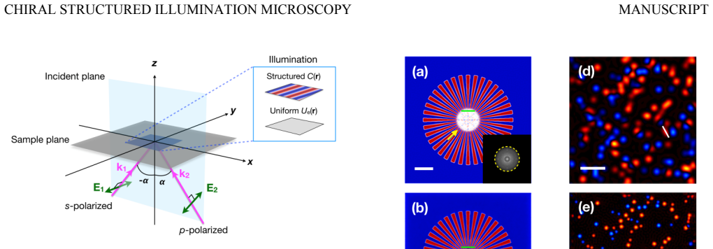
The central object is the optical chirality density $C(\mathbf{r})$, a scalar formed from the imaginary part of $\mathbf{E}^* \cdot \mathbf{B}$ that is positive for one handedness of the field and negative for the other. In Eq. (2) the molecular absorption splits into an electric-dipole term proportional to $U_e$ and a chirality term proportional to $C G''$; the structured-OC illumination is chosen so that only $C$ varies while $U_e$ stays flat. The two-plane-wave s/p superposition is the concrete generator: at incidence $\alpha$, the wave vector of the chirality stripe is $|\mathbf{k}_C| = 2 n k_0 \sin\alpha$, so with a high-NA objective the pattern can reach the SIM cutoff and yield the factor-of-two resolution gain. The reconstruction machinery is borrowed from SIM: phase-shift the pattern, Fourier transform, keep the shifted first-order components, recombine with weights, and invert.
What would settle it
Point the structured-chirality illumination at an achiral fluorophore sample and run the full chiral SIM reconstruction: any nonzero reconstructed image would prove that electric-dipole fluorescence is leaking into the $\pm1$ sidebands, since an achiral sample has no chirality-dependent absorption. A companion calculation of the electric-energy-density ripple under realistic numerical aperture, aberrations, and unequal beam amplitudes would show how large that leak is.
Extended reading notes
Core claim
The central claim is that spatially structuring the optical chirality of the illumination, rather than its intensity, lets fluorescence-detected circular dichroism reach sub-diffraction resolution. In the paper's own terms, the absorption rate of a chiral molecule is $A = (\omega/\varepsilon_0)(\alpha'' U_e - C G'')$, where $\alpha''$ is the imaginary electric-dipole polarizability and $G''$ the imaginary electric-magnetic mixed polarizability. Illuminating with the superposition of an s- and a p-polarized plane wave at $\pm \alpha$ produces a cosinusoidal optical chirality with a uniform $U_e$; the Fourier transform of the acquired FDCD fluorescence then contains an unwanted zeroth-order electric-dipole term and two first-order terms that carry the high-frequency chiral-domain information. The method discards the zeroth-order term, recombines the first-order terms from three pattern orientations and three phases, and uses an additional wide-field FDCD image to fix the absolute handedness phase. In finite-difference time-domain simulations of a chiral Siemens star and of 100/150-nm beads, the reconstructed chiral SIM image resolves features that the wide-field FDCD image blurs.
Load-bearing premise
The load-bearing assumption is that the illumination can be made to have striped optical chirality while its electric-field strength stays perfectly flat; in a real microscope, focusing, aberrations, reflections, or unequal beam amplitudes will make that field strength ripple, and the ripples will leak the bright chirality-blind fluorescence into the very sidebands that are supposed to carry only the weak chiral signal.
Editorial extensions
If this is right
- Chiral SIM gives about a factor-of-two resolution improvement over wide-field FDCD imaging, reaching roughly 100 nm for 405 nm excitation with NA 1.2, the same improvement factor as ordinary SIM.
- Because acquisition is wide-field and the reconstruction is the standard SIM pipeline, chiral domain maps can be obtained without point scanning, unlike confocal CD, SHG-CD, or two-photon chirality mapping.
- Samples with strong chiroptical response such as a dissymmetry factor around 0.37 should be imageable with no enhancement; samples with weak CD need either chirality-enhanced illumination or longer acquisition to keep the modulation-to-noise ratio high enough.
- Chiral-domain boundaries appear as spurious achiral regions in every CD imaging method, including this one, so reconstructed images must be interpreted with that artifact in mind.
- Extending the structured-OC pattern to plasmonic near fields could push the resolution beyond the far-field factor-of-two limit, as the paper itself suggests.
Reading between the lines
- Beyond the paper, the uniform-field requirement is not guaranteed by the two-plane-wave construction once a real objective, aberrations, or reflections enter, so practical performance will hinge on calibrating or suppressing electric-field-strength ripples; the paper gives no tolerance analysis for this.
- Beyond the paper, the supplement's noise ratio $R \propto m |g| \sqrt{N_+ + N_-}$ implies a quantitative trade-off between acquisition time and optical-chirality enhancement for weak-CD samples: halving the photon budget would need roughly a $\sqrt{2}$-fold enhancement factor to keep the same signal-to-noise ratio.
- Beyond the paper, one could validate the method on a lithographically defined racemic stripe pattern and measure the apparent width of the achiral boundary against the theoretical point-spread function; that measurement would separate true chirality contrast from SIM resolution gain.
Signed reviews
Editorial analysis
A structured set of objections, weighed in public.
Referee Report
Summary. The manuscript proposes a new super-resolution imaging modality, 'chiral SIM,' that combines structured illumination microscopy with optical chirality engineering and fluorescence-detected circular dichroism. The authors derive the fluorescence signal from the absorption rate of a chiral molecule, Eq. (2), and show that by structuring the optical chirality C(r) while keeping the electric energy density U_e(r) uniform, the Fourier-space ±1st-order sidebands contain high-spatial-frequency chiral-domain information that can be extracted and recombined to form a sub-diffraction-limited image, Eq. (5). They propose a far-field implementation using a pair of s- and p-polarized plane waves (Fig. 2), verify the structured chirality pattern with FDTD simulations, and demonstrate image reconstruction on simulated Siemens-star and nanobead samples (Fig. 3). A supplemental noise analysis addresses weak-CD samples and required optical chirality enhancement. The paper claims a maximum resolution improvement of roughly two over wide-field FDCD imaging, i.e., about 100 nm for 405 nm excitation and NA=1.2.
Significance. If the central claim holds, this is a genuinely new wide-field super-resolution imaging concept for chiral samples, filling a gap left by existing chiral imaging methods that are scanning, low-throughput, or diffraction-limited. The paper provides an explicit analytic derivation, FDTD-simulated illumination patterns, a noise model with quantitative photon-count and enhancement-factor estimates (Fig. S2), and falsifiable predictions about achievable resolution. The ideal-case physics is sound, and the synthetic reconstruction demonstrates the algorithm consistently. The main risk is the practical realizability of the key condition U_e(r)=U_e in a real high-NA focusing system, for which the paper currently provides no tolerance analysis.
major comments (3)
- [Main text after Eq. (5); Supplement S.3 and S.4] The central reconstruction procedure discards the 0th-order electric-dipole term under the condition U_e(r)=U_e, stated after Eq. (5). The only support for this condition is the ideal two-plane-wave calculation in Eqs. (S.3)-(S.9) and an FDTD simulation with Bloch boundary conditions (S.3), which imposes the same ideal periodicity. A real implementation using a high-NA objective, as described in Fig. 2, will introduce vectorial focusing, apodization, aberrations, and unequal s/p amplitude transmission, producing U_e ripples at the same spatial frequency k_C as the chirality pattern. Because the achiral electric-dipole fluorescence exceeds the chiral modulation by a factor on the order of 2/g (about 5.4 for the simulated g=0.37), even a few percent U_e ripple can leak a substantial fraction of the discarded 0th-order term into the extracted ±1st-order sidebands. I request either an explicit bound on the acceptable relative U_e ripple as a function of the sample's dissymmetry factor, or an end-to-end simulation that uses a realistic vectorial high-NA illumination field with the resulting U_e(r) included in the forward model and demonstrates that the reconstructed chiral image remains artifact-free.
- [Supplemental Material S.1] The reconstruction requires the absolute phase (argument) of the ±1st-order components, and the authors state that an extra wide-field FDCD image must be acquired for this purpose, but no concrete procedure or simulation is provided. In standard SIM the phases are either pre-calibrated or estimated from the raw data; here, the 0th-order component is intentionally discarded, making the phase-reference step nontrivial. Errors in assigning these phases will directly corrupt the reconstructed chiral image. Please specify how the wide-field FDCD image is used to determine the phases and test the procedure under noisy, uncertain illumination phases.
- [Fig. 3 and Eq. (6)] The claimed 'highest spatial resolution improvement ... ~2' is derived analytically from Eq. (6), but the simulations do not quantitatively measure the achieved resolution; the demonstration relies on visual inspection of line profiles and images. Since sub-diffraction resolution is the paper's central claim, I suggest extracting a quantitative resolution estimate from the reconstructed images (e.g., from the Siemens-star contrast or from fits to the bead profiles) and comparing it with the theoretical prediction, including a noise or U_e-ripple sensitivity study.
minor comments (5)
- [Fig. 3 caption] The caption contains the typo 'chrial SIM'; it should read 'chiral SIM'.
- [Main text and Eq. (S.2)] The dissymmetry factor g is used in the main text before it is defined; please define it in the main text or explicitly refer to Eq. (S.2) where it is introduced.
- [Supplemental Material S.4] The equation numbering in the supplement is inconsistent: Eq. (S.3) is used both for the noise ratio in S.2 and for the electric field in S.4, and the numbering should be made sequential and unique.
- [Supplemental Material S.2] The relation between the maximum photon number per pixel (10^5) used in the main-text simulation and the quantities N_+ and N_- in Eq. (S.3) should be stated explicitly, including how the photon budget maps to the shot-noise-dominated regime assumed in the analysis.
- [Eq. (6)] For clarity, Eq. (6) should state the corresponding wide-field resolution expression used to compute the factor-of-two improvement, since the conventional Abbe criterion is often written with an additional numerical factor.
Circularity Check
No significant circularity: the reconstruction follows directly from Eqs. (1)-(5) and the resolution claim from the analytical k-vector formula, with no fitted result or load-bearing self-citation.
full rationale
The derivation is self-contained and non-circular. The reconstruction model in Eqs. (4)-(5) is a direct Fourier decomposition of the absorption-rate expression in Eqs. (1)-(2), with no parameter fitted to the final images. The structured-optical-chirality illumination is derived analytically in the supplement (Eqs. S.3-S.9) from a specified pair of plane waves; the uniform electric-energy-density condition U_e(r)=U_e is stated explicitly as a requirement, and the FDTD simulation implements the same idealization. The claimed resolution gain follows from the analytical k-vector relation k_C = 2 n k_0 sin(alpha) (Eq. S.9 and S.10) and the standard SIM cutoff formula (Eq. 6), not from a fitted or renamed output. The Siemens-star and bead simulations are forward-model demonstrations: a known chiral distribution is propagated through Eq. (4) and then reconstructed, so reconstruction correctness is tested rather than assumed. Self-citations to SIM literature (Refs. 29-32) are standard foundational references, and the dissymmetry factor g = 0.37 is taken from independent external work (Ref. 11). The practical concern that a real high-NA objective could create U_e ripples that leak achiral fluorescence into the +/-1st-order terms is a feasibility and robustness limitation, not a circularity: it concerns whether the stated ideal conditions can be met experimentally, not whether the derivation assumes its conclusion. No load-bearing step reduces by construction to its own input.
Assumptions & free parameters
free parameters (2)
- k_C/k_cutoff ratio =
0.7
- maximum photon number per pixel =
10^5
assumptions (6)
- domain assumption Absorption rate of a chiral molecule is A = (omega/2)[alpha''|E|^2 + (2/omega)G'' Im(E* dot B)], with magnetic susceptibility and higher-order multipoles neglected.
- domain assumption Fluorescence intensity is proportional to absorption rate: F(r) = beta A(r), with constant quantum yield and detection efficiency beta.
- domain assumption During structured chiral illumination, the electric energy density U_e(r) is uniform while the optical chirality is C(r) = C0 cos(k_C dot r + theta).
- domain assumption Camera noise is dominated by shot noise, so noise scales as the square root of the total received photon number.
- standard math Standard SIM reconstruction, using three orientations, three phases, and known pattern parameters, recovers the object when the plus and minus 1st-order components are separated and recombined.
- domain assumption Boundaries between opposite chiral domains appear as zero-CD 'pseudo achiral' regions due to finite resolution.
Cite this review
Pith. "Pith review of Chiral Structured Illumination Microscopy." pith.science (2026). https://pith.science/paper/KVRWXH5I
@misc{pith2026190809391,
  author       = {Pith},
  title        = {Pith review of: Chiral Structured Illumination Microscopy},
  year         = {2026},
  howpublished = {\url{https://pith.science/paper/KVRWXH5I}},
  note         = {Machine review of arXiv:1908.09391}
}
read the original abstract
We propose a chiral imaging modality based on optical chirality engineering, fluorescence-detected circular dichroism and structured illumination microscopy. In this method, the optical chirality of the illumination is structured and the circular dichroism dependent fluorescence is detected. With image reconstruction, the spatial distribution of chiral domains can be obtained at sub-diffraction limited resolution. We theoretically demonstrate this method and discuss the feasibility using an optical chirality engineering approach based on far-field optics.
Figures


Reference graph
Works this paper leans on
- [1]
-
[2]
K. W. Busch and M. A. Busch, Chiral analysis (Elsevier, Amsterdam, 2011)
work page 2011
-
[3]
N. J. Greenfield, Nat. Protoc. 1, 2876 (2006)
work page 2006
- [4]
-
[5]
The simulated wide-field FDCD and chiral SIM images of the Siem ens star are shown in Figs 3(a) and (b), respectively. As can be seen, the chiral SIM image has a reduced blurry central area, indicating an improved spatial resolution due to the expanded k-space FIG. 3. Theoretical demonstration of chiral SIM. (a) Simulated wide-field FDCD image and (b) sim...
work page 2018
-
[6]
A. Micsonai, F. Wien, L. Kernya, Y.-H. Lee, Y. Goto, M. Réfrégiers, and J. Kardos, Proc. Natl. Acad. Sci. U.S.A. 112, E3095 (2015)
work page 2015
-
[7]
A. J. Miles and B. A. Wallace, Chem. Soc. Rev. 45, 4859 (2016)
work page 2016
- [8]
Show all 44 references
-
[9]
Claborn, E
K. Claborn, E. Puklin-Faucher, M. Kurimoto, W. Kaminsky, and B. Kahr, J. Am. Chem. Soc. 125, 14825 (2003)
2003
-
[10]
Arteaga, M
O. Arteaga, M. Baldrís, J. Antó, A. Canillas, E. Pascual, and E. Bertran, Appl. Opt. 53, 2236 (2014)
2014
-
[11]
Mickols and M
W. Mickols and M. F. Maestre, Rev. Sci. Instrum. 59, 867 (1988)
1988
-
[12]
Savoini, P
M. Savoini, P. Biagioni, S. C. Meskers, L. Duo, B. Hecht, and M. Finazzi, J. Phys. Chem. Lett. 2, 1359 (2011)
2011
-
[13]
L. M. Haupert and G. J. Simpson, Annu. Rev. Phys. Chem. 60, 345 (2009)
2009
-
[14]
X. Chen, O. Nadiarynkh, S. Plotnikov, and P. J. Campagnola, Nat. Protoc. 7, 654 (2012)
2012
-
[15]
Mazumder, J
N. Mazumder, J. Qiu, M. R. Foreman, C. M. Romero, C.-W. Hu, H.-R. Tsai, P. Török, and F.-J. Kao, Opt. Express 20, 14090 (2012)
2012
-
[16]
H. Lee, M. J. Huttunen, K.-J. Hsu, M. Partanen, G.-Y. Zhuo, M. Kauranen, and S.-W. Chu, Biomed. Opt. Express 4, 909 (2013)
2013
-
[17]
G.-Y. Zhuo, H. Lee, K.-J. Hsu, M. Huttunen, M. Kauranen, Y.-Y. Lin, and S.-W. Chu, J. Microsc. 253, 183 (2014)
2014
-
[18]
S. P. Rodrigues, S. Lan, L. Kang, Y. Cui, and W. Cai, Adv. Mater. 26, 6157 (2014)
2014
-
[19]
K. R. Campbell and P. J. Campagnola, J. Phys. Chem. B 121, 1749 (2017)
2017
-
[20]
Savoini, X
M. Savoini, X. Wu, M. Celebrano, J. Ziegler, P. Biagioni, S. C. Meskers, L. Du ò, B. Hecht, and M. Finazzi, J. Am. Chem. Soc. 134, 5832 (2012)
2012
-
[21]
Mawatari, S
K. Mawatari, S. Kubota, and T. Kitamori, Anal. Bioanal. Chem. 391, 2521 (2008)
2008
-
[22]
Liu and M
M. Liu and M. Franko, Crit. Rev. Anal. Chem. 44, 328 (2014)
2014
-
[23]
Savoini, P
M. Savoini, P. Biagioni, G. Lakhwani, S. Meskers, L. Duo, and M. Finazzi, Opt. Lett. 34, 3571 (2009)
2009
-
[24]
Tantussi, F
F. Tantussi, F. Fuso, M. Allegrini, N. Micali, I. G. Occhiuto, L. M. Scolaro, and S. Patanè, Nanoscale 6, 10874 (2014)
2014
-
[25]
Nishiyama and H
Y. Nishiyama and H. Okamoto, J. Phys. Chem. C 120, 28157 (2016)
2016
-
[26]
Tang and A
Y. Tang and A. E. Cohen, Phys. Rev. Lett. 104, 163901 (2010)
2010
-
[27]
D. H. Turner, I. Tinoco Jr, and M. Maestre, J. Am. Chem. Soc. 96, 4340 (1974)
1974
-
[28]
Ehrenberg and I
B. Ehrenberg and I. Steinberg, J. Am. Chem. Soc. 98, 1293 (1976)
1976
-
[29]
Tinoco Jr and D
I. Tinoco Jr and D. H. Turner, J. Am. Chem. Soc. 98, 6453 (1976)
1976
-
[30]
Heintzmann and C
R. Heintzmann and C. G. Cremer, SPIE Proc. 3568, 185 (1999)
1999
-
[31]
M. G. Gustafsson, J. Microsc. 198, 82 (2000)
2000
-
[32]
Jost and R
A. Jost and R. Heintzmann, Annu. Rev. Mater. Res. 43, 261 (2013)
2013
-
[33]
Ingerman, R
E. Ingerman, R. London, R. Heintzmann, and M. Gustafsson, J. Microsc. 273, 3 (2019)
2019
-
[34]
Tang and A
Y. Tang and A. E. Cohen, Science 332, 333 (2011). CHIRAL STRUCTURED ILLUMINATION MICROSCOPY MANUSCRIPT
2011
-
[35]
Schäferling, X
M. Schäferling, X. Yin, and H. Giessen, Opt. Express 20, 26326 (2012)
2012
-
[36]
Lin and J.-S
D. Lin and J.-S. Huang, Opt. Express 22, 7434 (2014)
2014
-
[37]
M. L. Tseng, Z. H. Lin, H. Y. Kuo, T. T. Huang, Y. T. Huang, T. L. Chung, C. H. Ch u, J. S. Huang, and D. P. Tsai, Adv. Opt. Mater. 7, 1900617 (2019)
2019
-
[38]
H. Hu, Q. Gan, and Q. Zhan, Phys. Rev. Lett. 122, 223901 (2019)
2019
-
[39]
Wicker and R
K. Wicker and R. Heintzmann, Nat. Photonics 8, 342 (2014)
2014
-
[40]
M. Oda, H. G. Nothofer , G. Lieser, U. Scherf, S. Meskers, and D. Neher, Adv. Mater. 12, 362 (2000)
2000
-
[41]
J. L. Ponsetto et al., ACS nano 11, 5344 (2017)
2017
-
[42]
J. T. Collins, C. Kuppe, D. C. Hooper, C. Sibilia, M. Centini, and V. K. Valev, Adv. Opt. Mater. 5, 1700182 (2017)
2017
-
[43]
S. H. Choi et al., Nature 515, 274 (2014)
2014
-
[44]
dissymmetry factor
W. Ma, L. Xu, A. F. de Moura, X. Wu, H. Kuang, C. Xu, and N. A. Kotov, Chem. Rev. 117, 8041 (2017). MANUSCRIPT Chiral Structured Illumination Microscopy – Supplemental Material Shiang-Yu Huang,1 Jiwei Zhang,1 Christian Karras,1 Ronny Förster,1 Rainer Heintzmann1,2,3,* and Jer-...
2017
Reviewed August 14, 2026 · model on record in the stance chip above.
Discussion (0). Continue with ORCID to comment.