SPARC: A Multi-Agent System for Electrical Circuit Question Answering
Pith reviewed 2026-06-27 21:42 UTC · model grok-4.3
The pith
SPARC uses LLM agents to synthesize and run physics simulations for answering electrical circuit diagram questions.
A machine-rendered reading of the paper's core claim, the machinery that carries it, and where it could break.
Core claim
SPARC achieves 83% accuracy on electrical circuit diagram QA tasks, with up to a 58% absolute improvement over baselines, while enabling systematic error diagnosis. It does so by using LLM agents to synthesize, execute, and analyze simulation programs that are grounded in executable physics-based simulations rather than relying on the model alone.
What carries the argument
The multi-agent LLM workflow that synthesizes, executes, and analyzes physics-based simulation programs to ground answers about circuit diagrams.
If this is right
- The system reaches 83 percent accuracy on circuit diagram questions.
- It delivers up to 58 percent absolute gains compared with existing baselines.
- It produces traceable steps that support systematic diagnosis of reasoning errors.
- Reasoning is shifted from model-internal knowledge to executable physics simulations.
Where Pith is reading between the lines
- The same agent structure might apply to other diagram-based physical reasoning problems where simulation code can be written and run.
- Error traces from the simulation steps could be used to generate targeted feedback in tutoring systems.
- If the generated simulation code is stored, it could serve as a reusable library for similar future questions.
Load-bearing premise
That grounding reasoning in executable physics-based simulations via LLM agents to synthesize, execute, and analyze simulation programs will improve accuracy and reliability for electrical circuit diagram QA tasks.
What would settle it
If a controlled test on a new set of circuit questions shows that the simulation-grounded answers match ground truth no more often than strong baseline multimodal LLMs, the accuracy and reliability claims would not hold.
Figures


read the original abstract
Electrical circuit diagram QA tasks require complex mathematical reasoning, which remains challenging for multimodal LLMs. We present SPARC, a multi-agent system that answers questions over circuit diagrams by grounding reasoning in executable physics-based simulations. SPARC uses LLM agents to synthesize, execute, and analyze simulation programs, improving accuracy and reliability by design. It achieves 83% accuracy, with up to a 58% absolute improvement over baselines, while enabling systematic error diagnosis.
Editorial analysis
A structured set of objections, weighed in public.
Referee Report
Summary. The paper presents SPARC, a multi-agent system for electrical circuit diagram question answering. LLM agents synthesize, execute, and analyze physics-based simulation programs to ground reasoning, with the abstract claiming 83% accuracy and up to 58% absolute improvement over baselines while enabling systematic error diagnosis.
Significance. If the reported accuracy gains and error-diagnosis capability are substantiated with full experimental details, the work could contribute to reliable multimodal reasoning in domains that require executable physical simulation, by demonstrating a design pattern for agent-based grounding that reduces hallucination in circuit QA tasks.
major comments (1)
- [Abstract] Abstract: the stated 83% accuracy and 58% absolute improvement are presented without any description of the dataset, baseline definitions, evaluation protocol, number of trials, or error analysis, rendering it impossible to determine whether the numbers support the central claim of improved accuracy and reliability by design.
Simulated Author's Rebuttal
We thank the referee for the detailed feedback. We address the major comment on the abstract below and agree that revisions are needed to strengthen the presentation of results.
read point-by-point responses
-
Referee: [Abstract] Abstract: the stated 83% accuracy and 58% absolute improvement are presented without any description of the dataset, baseline definitions, evaluation protocol, number of trials, or error analysis, rendering it impossible to determine whether the numbers support the central claim of improved accuracy and reliability by design.
Authors: We agree with the referee that the abstract, in its current form, lacks sufficient context to allow independent assessment of the reported metrics. The full manuscript contains the requested details in the experimental sections, but we acknowledge that the abstract should be more self-contained. We will revise the abstract to briefly describe the CircuitQA dataset, the primary baselines (including multimodal LLMs), the evaluation protocol (exact-match accuracy with simulation verification), the number of evaluation runs, and the error analysis approach. This change will directly address the concern and make the central claims verifiable from the abstract. revision: yes
Circularity Check
No significant circularity detected
full rationale
The paper describes an empirical multi-agent system (SPARC) for circuit diagram QA that synthesizes and executes simulation programs via LLMs, reporting 83% accuracy on unspecified tasks. No derivation chain, equations, fitted parameters, or first-principles predictions are present in the provided abstract or described claims. The central result is an accuracy number obtained by running the system on benchmarks, which is an external empirical measurement rather than a quantity defined in terms of itself or reduced by self-citation. No self-definitional, fitted-input, or uniqueness-imported steps exist. The work is therefore self-contained against external benchmarks with no detectable circularity.
Axiom & Free-Parameter Ledger
Reference graph
Works this paper leans on
-
[1]
Making the V in VQA Matter: Elevating the Role of Image Understanding in Visual Question Answering
guided mllm reasoning: Enhancing mllm with knowledge and visual notes for visual question an- swering. InProceedings of the Computer Vision and Pattern Recognition Conference, pages 19597– 19607. Ali Mazraeh Farahani, Peyman Adibi, Moham- mad Saeed Ehsani, Hans-Peter Hutter, and Alireza Darvishy. 2025. Chart question answering with mul- timodal graph repr...
work page internal anchor Pith review Pith/arXiv arXiv 2025
-
[2]
hdbscan: Hierarchical density based clustering. J. Open Source Softw., 2(11):205. Rahul Mehta, Bhavyajeet Singh, Vasudeva Varma, and Manish Gupta. 2024. Circuitvqa: A visual ques- tion answering dataset for electrical circuit images. InMachine Learning and Knowledge Discovery in Databases. Research Track: European Conference, ECML PKDD 2024, Vilnius, Lith...
-
[3]
In2023 International Conference on Digital Image Computing: Techniques and Applications (DICTA), pages 364–370
Automated netlist generation from offline hand-drawn circuit diagrams. In2023 International Conference on Digital Image Computing: Techniques and Applications (DICTA), pages 364–370. IEEE. Shaowei Wang, Lingling Zhang, Longji Zhu, Tao Qin, Kim-Hui Yap, Xinyu Zhang, and Jun Liu. 2024a. Cog-dqa: Chain-of-guiding learning with large lan- guage models for dia...
2025
-
[4]
Supply frequency
are model-agnostic, we instantiate them us- ing our strongest performing model for a fair com- parison. For NOTEMR, we follow the original pipeline by using LLaV A for visual grounding and Grad-CAM based region selection, and then use our best-performing vision language model, GPT- 5.1 for the final QA stage. For MATHSENSEI, we compare against its best-pe...
2026
-
[5]
This repeats until execution succeeds or retry limit T is reached
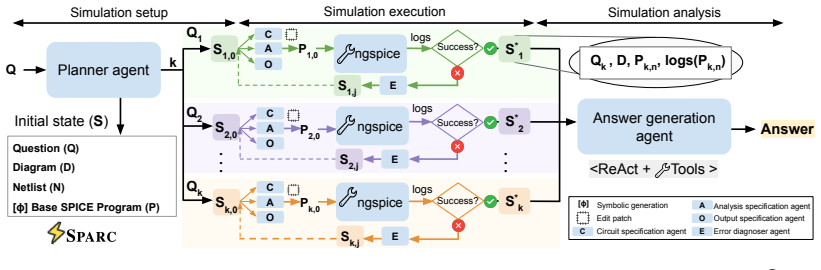
Otherwise, anerror analyzeridentifies the faulty section and selectively re-invokes the responsible agent for repair, yielding updated states such as S1,1. This repeats until execution succeeds or retry limit T is reached. Finally, theanswer generation agent aggregates the successful simulation logs and uses tool based calculations to produce the final an...
-
[6]
steady state
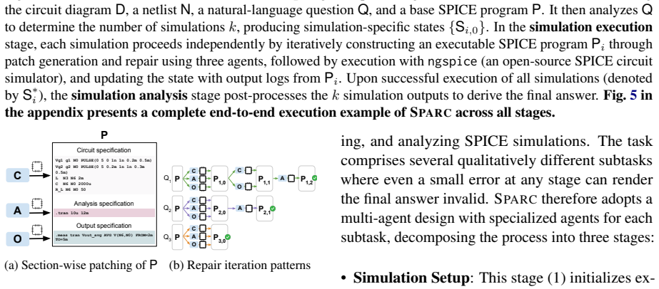
for all components. The circuit specification agent replaces those placeholders with the values stated in the question. Base (excerpt) – placeholder values from netlist R1 N1 N2 1 (* placeholder – will be updated to 6 *) L1 N2 N3 1 (* placeholder – will be updated *) V1 N1 0 AC 1 (* amplitude and frequency not yet set *) Patch – values from question appli...
2024
-
[7]
One prior work (Nau et al., 2025) does use SPICE but for a completelydifferenttask: electrical power system design automation
and netlist extraction (Shi et al., 2025), and (2) benchmarks without concrete mechanisms (Li et al., 2025). One prior work (Nau et al., 2025) does use SPICE but for a completelydifferenttask: electrical power system design automation. General Diagram Question Answering.Prior work on general diagram question answering falls into two categories. The first ...
2025
-
[8]
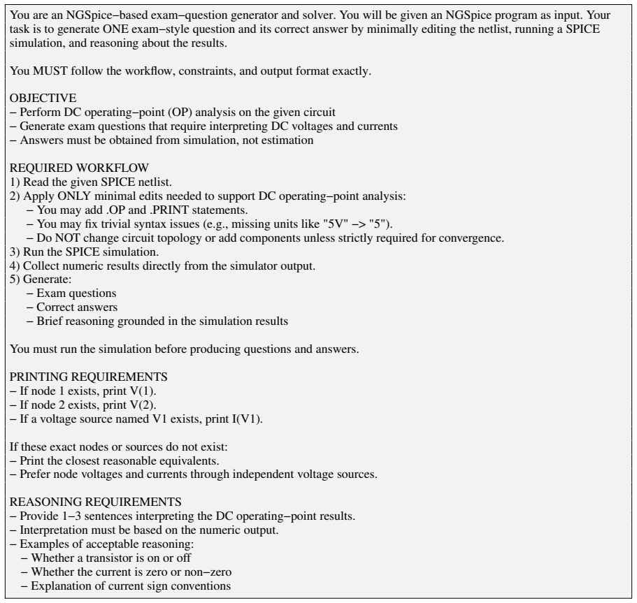
Read the given SPICE netlist
-
[9]
5V" −> "5
Apply ONLY minimal edits needed to support DC operating−point analysis: − You may add .OP and .PRINT statements. − You may fix trivial syntax issues (e.g., missing units like "5V" −> "5"). − Do NOT change circuit topology or add components unless strictly required for convergence
-
[10]
Run the SPICE simulation
-
[11]
Collect numeric results directly from the simulator output
-
[12]
PRINTING REQUIREMENTS − If node 1 exists, print V(1)
Generate: − Exam questions − Correct answers − Brief reasoning grounded in the simulation results You must run the simulation before producing questions and answers. PRINTING REQUIREMENTS − If node 1 exists, print V(1). − If node 2 exists, print V(2). − If a voltage source named V1 exists, print I(V1). If these exact nodes or sources do not exist: − Print...
-
[13]
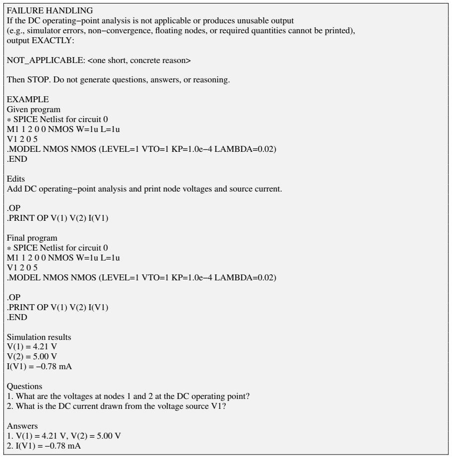
What are the voltages at nodes 1 and 2 at the DC operating point?
-
[14]
What is the DC current drawn from the voltage source V1? Answers
-
[16]
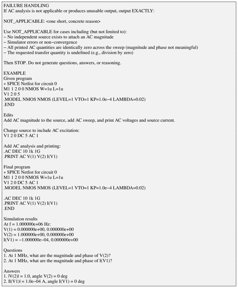
I(V1) = −0.78 mA Figure 8: DC operating-point analysis demonstration prompt. 21 FAILURE HANDLING If AC analysis is not applicable or produces unusable output, output EXACTLY: NOT_APPLICABLE: <one short, concrete reason> Use NOT_APPLICABLE for cases including (but not limited to): − No independent source exists to attach an AC magnitude − Simulator errors ...
-
[17]
At 1 MHz, what are the magnitude and phase of V(2)?
-
[18]
At 1 MHz, what are the magnitude and phase of I(V1)? Answers
-
[19]
|V(2)| = 1.0, angle V(2) = 0 deg
-
[20]
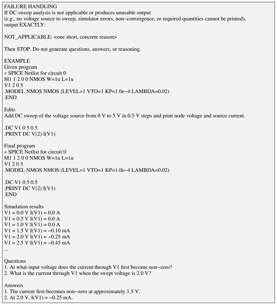
|I(V1)| = 1.0e−04 A, angle I(V1) = 0 deg Figure 9: AC small-signal analysis demonstration prompt. 22 FAILURE HANDLING If DC sweep analysis is not applicable or produces unusable output (e.g., no voltage source to sweep, simulator errors, non−convergence, or required quantities cannot be printed), output EXACTLY: NOT_APPLICABLE: <one short, concrete reason...
-
[21]
At what input voltage does the current through V1 first become non−zero?
-
[22]
What is the current through V1 when the swept voltage is 2.0 V? Answers
-
[23]
The current first becomes non−zero at approximately 1.5 V
-
[24]
Figure 10: DC parameter sweep demonstration prompt
At 2.0 V, I(V1) = −0.25 mA. Figure 10: DC parameter sweep demonstration prompt. 23 FAILURE HANDLING If transient analysis is not applicable or produces unusable output (e.g., simulator errors, non−convergence, floating nodes, or required quantities cannot be printed), output EXACTLY: NOT_APPLICABLE: <one short, concrete reason> Then STOP. Do not generate ...
-
[25]
At t = 100 ns, what are the voltages at nodes 1 and 2?
-
[26]
At t = 100 ns, what is the current through the voltage source V1? Answers
-
[27]
V(1) = 4.21 V, V(2) = 5.00 V
-
[28]
24 You are an expert in circuit analysis
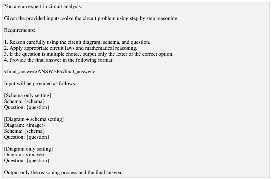
I(V1) = −0.78 mA Figure 11: transient analysis demonstration prompt. 24 You are an expert in circuit analysis. Given the provided inputs, solve the circuit problem using step by step reasoning. Requirements:
-
[29]
Reason carefully using the circuit diagram, schema, and question
-
[30]
Apply appropriate circuit laws and mathematical reasoning
-
[31]
If the question is multiple choice, output only the letter of the correct option
-
[32]
Provide the final answer in the following format: <final_answer>ANSWER</final_answer> Input will be provided as follows. [Schema only setting] Schema: {schema} Question: {question} [Diagram + schema setting] Diagram: <image> Schema: {schema} Question: {question} [Diagram only setting] Diagram: <image> Question: {question} Output only the reasoning process...
-
[33]
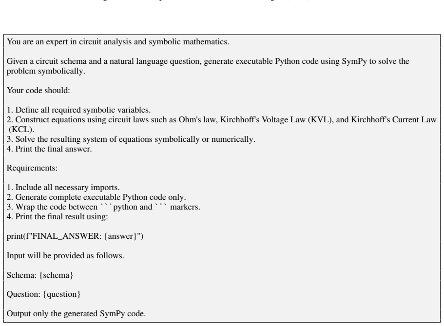
Define all required symbolic variables
-
[34]
Construct equations using circuit laws such as Ohm's law, Kirchhoff's V oltage Law (KVL), and Kirchhoff's Current Law (KCL)
-
[35]
Solve the resulting system of equations symbolically or numerically
-
[36]
Requirements:
Print the final answer. Requirements:
-
[37]
Include all necessary imports
-
[38]
Generate complete executable Python code only
-
[39]
Wrap the code between```python and```markers
-
[40]
FINAL_ANSWER: {answer}
Print the final result using: print(f"FINAL_ANSWER: {answer}") Input will be provided as follows. Schema: {schema} Question: {question} Output only the generated SymPy code. Figure 13: Prompt used for the CODEbaseline 25 You are an expert in planning NGSpice simulations from a circuit schema and a natural language question. Given the user's question, the ...
-
[41]
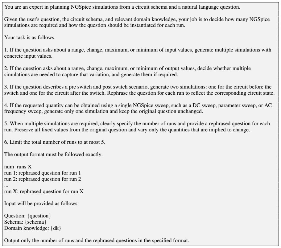
If the question asks about a range, change, maximum, or minimum of input values, generate multiple simulations with concrete input values
-
[42]
If the question asks about a range, change, maximum, or minimum of output values, decide whether multiple simulations are needed to capture that variation, and generate them if required
-
[43]
Rephrase the question for each run to reflect the corresponding circuit state
If the question describes a pre switch and post switch scenario, generate two simulations: one for the circuit before the switch and one for the circuit after the switch. Rephrase the question for each run to reflect the corresponding circuit state
-
[44]
If the requested quantity can be obtained using a single NGSpice sweep, such as a DC sweep, parameter sweep, or AC frequency sweep, generate only one simulation and keep the original question unchanged
-
[45]
Preserve all fixed values from the original question and vary only the quantities that are implied to change
When multiple simulations are required, clearly specify the number of runs and provide a rephrased question for each run. Preserve all fixed values from the original question and vary only the quantities that are implied to change
-
[46]
The output format must be followed exactly
Limit the total number of runs to at most 5. The output format must be followed exactly. num_runs X run 1: rephrased question for run 1 run 2: rephrased question for run 2 ... run X: rephrased question for run X Input will be provided as follows. Question: {question} Schema: {schema} Domain knowledge: {dk} Output only the number of runs and the rephrased ...
-
[47]
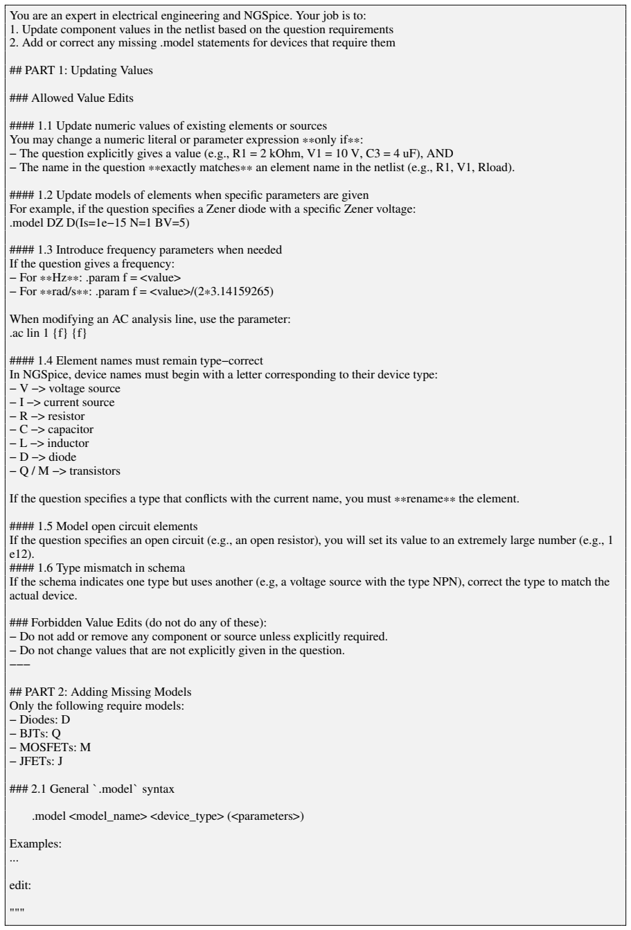
Update component values in the netlist based on the question requirements
-
[48]
Add or correct any missing .model statements for devices that require them ## PART 1: Updating Values ### Allowed Value Edits #### 1.1 Update numeric values of existing elements or sources You may change a numeric literal or parameter expression**only if**: − The question explicitly gives a value (e.g., R1 = 2 kOhm, V1 = 10 V, C3 = 4 uF), AND − The name i...
-
[49]
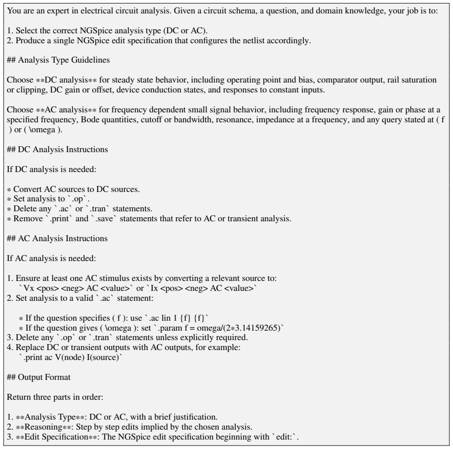
Select the correct NGSpice analysis type (DC or AC)
-
[50]
Produce a single NGSpice edit specification that configures the netlist accordingly. ## Analysis Type Guidelines Choose **DC analysis** for steady state behavior, including operating point and bias, comparator output, rail saturation or clipping, DC gain or offset, device conduction states, and responses to constant inputs. Choose **AC analysis** for freq...
-
[51]
Ensure at least one AC stimulus exists by converting a relevant source to: `Vx <pos> <neg> AC <value>`or`Ix <pos> <neg> AC <value>`
-
[52]
Set analysis to a valid`.ac`statement: * If the question specifies ( f ): use`.ac lin 1 {f} {f}` * If the question gives ( \omega ): set`.param f = omega/(2 *3.14159265)`
-
[53]
Delete any`.op`or`.tran`statements unless explicitly required
-
[54]
Replace DC or transient outputs with AC outputs, for example: `.print ac V(node) I(source)` ## Output Format Return three parts in order:
-
[55]
**Analysis Type**: DC or AC, with a brief justification
-
[56]
**Reasoning**: Step by step edits implied by the chosen analysis
-
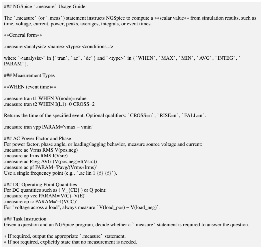
[57]
voltage across a load
**Edit Specification**: The NGSpice edit specification beginning with`edit:`. Figure 16: Prompt used for analysis specification agent 28 ### NGSpice`.measure`Usage Guide The`.measure`(or`.meas`) statement instructs NGSpice to compute a **scalar value** from simulation results, such as time, voltage, current, power, peaks, averages, integrals, or event tim...
discussion (0)
Sign in with ORCID, Apple, or X to comment. Anyone can read and Pith papers without signing in.