REVIEW 4 major objections 5 minor 19 references
Test mass charge management in the detection of gravitational waves in space based on UV micro-LED
T0 review · 4 major / 5 minor · reviewed 2026-08-06 · deepseek-v4-flash
Pith's one-line read UV micro-LEDs can replace larger UV LEDs to control test-mass charge in space gravitational wave detectors, keeping the test mass within ±100 mV and surviving mechanical and thermal qualification with less than 5% drift.
desk verdict A useful multi-wavelength micro-LED charge management demonstration, but the missing vacuum specification for the discharge tests is a load-bearing omission that needs to be resolved before the TRL-5 claim can be taken seriously. read the letter →
The pith
A machine-rendered reading of the paper's core claim, the machinery that carries it, and where it could break.
The reading
What carries the argument
The load-bearing objects are UV micro-LEDs, semiconductor light emitters about 100 µm across, operating at peak wavelengths 254, 262, 274, and 282 nm, mounted inside an electrode housing so their UV light strikes both the gold-coated test mass and the housing. The mechanism is photoelectric emission: photons eject electrons from the gold surfaces, changing the test mass's net charge. Optical power is set by pulse-width modulation (PWM) of the drive current, and measured discharge rates near 0 V are proportional to relative optical power with wavelength-dependent slopes (e.g., 2.31 V/s for 254 nm versus 0.008 V/s for 282 nm at full intensity). This proportionality is the control law that ties emitter settings to test-mass potential.
What would settle it
Measure the discharge rate of a 274 nm micro-LED at 1 µA drive current with 1 µs PWM pulses on a ~10 pF test mass and compare with the predicted ~10 charges/s; a deviation by more than a factor of a few, or a nonlinear I-P curve below 0.01 mA, would falsify the quiet-period continuous charge management claim.
Extended reading notes
Core claim
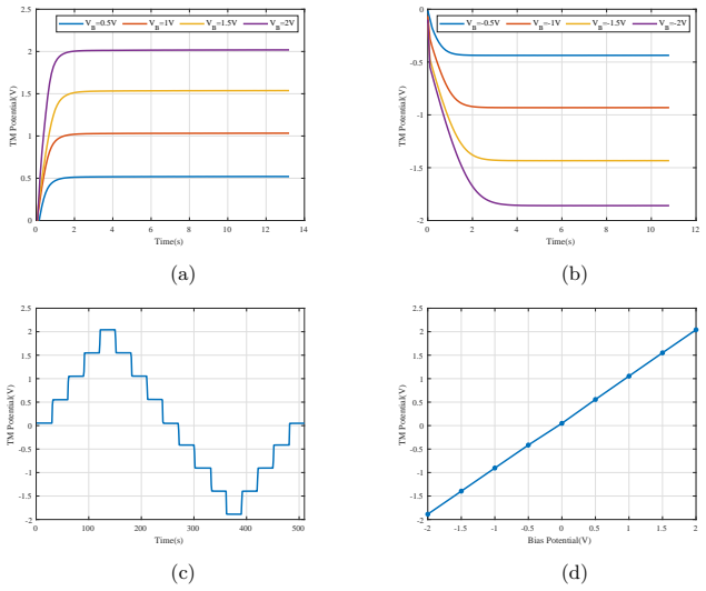
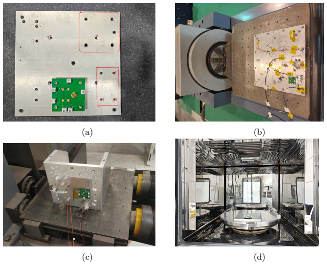
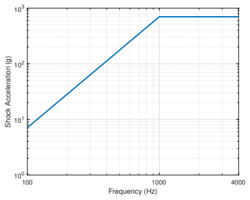
The paper's central claim is that UV micro-LEDs can serve as the light source for photoelectric charge management of a test mass in a space-based gravitational wave detector. Using four micro-LEDs with peak wavelengths 254, 262, 274, and 282 nm illuminating a gold-coated 46 mm cubic test mass in an electrode housing, the authors show the test-mass potential can be discharged from either polarity and brought to wavelength-dependent equilibrium potentials of −41 to +50 mV (274 nm: −10 mV, closest to zero). Varying drive current (0.01–1 mA) and PWM duty cycle (10–100%) gives an output optical power that controls the discharge rate, and near zero volts the discharge rate is linear in relative intensity with wavelength-dependent slopes. The same setup keeps the test mass within ±100 mV, with drift below 1 mV over 4 hours. After sinusoidal and random vibration, shock, and thermal cycling (−20 to +60 °C, 6.5 cycles), the V-I, I-P, and spectral characteristics changed by less than 5%, which the paper takes as raising the device to TRL-5.
Load-bearing premise
The load-bearing premise is the Section 4 extrapolation: the linear relationship between discharge rate and relative optical power, measured at drive currents of 0.01 mA or more, is assumed to continue down to a 1 µA drive and 1 µs pulse setting, giving a discharge rate of about 10 charges/s for quiet solar periods; that regime was not measured.
Editorial extensions
If this is right
- With micro-LEDs, a charge management unit can be physically smaller and lighter, and the emitter can in principle sit inside the electrode housing without optical fiber, removing UV-induced fiber attenuation.
- The linear control law between PWM duty cycle and discharge rate gives an open-loop knob for setting residual charge, so a desired equilibrium potential can be reached predictably.
- Because 274 nm gives an equilibrium potential of −10 mV while other wavelengths give +50 or −41 mV, the system has a wavelength choice for minimizing residual charge.
- After launch-representative vibration, shock, and thermal cycling, optical power output changed less than 5%, indicating the photoelectric charging performance will survive the launch environment.
- The four-hour test with drift below 1 mV demonstrates the micro-LED can hold the test mass inside the ±100 mV window, which is the precision needed for gravitational reference sensors.
Reading between the lines
- Looking beyond the paper, the measured wavelength dependence of equilibrium potential suggests a two-wavelength micro-LED pair could be driven in opposite proportions to null the equilibrium to 0 V, something the paper does not propose.
- If the 1 µA / 1 µs extrapolated discharge rate of ~10 charges/s holds, micro-LEDs could serve as a fine-trim actuator during quiet solar periods, while a brighter UV LED handles solar energetic particle events; this hybrid architecture is an extension the paper leaves implicit.
- A natural next test, which the paper itself flags, is vacuum-compatible radiation and thermal cycling; until that is done the TRL-5 rating should be read as a launch-survivability statement rather than an end-of-life reliability statement.
- The direct integration of micro-LEDs into the electrode housing without optical fiber would eliminate UV-induced fiber attenuation as a failure mode, but also requires demonstrating that emitted light hitting housing walls still produces adequate photoelectric yield—a configuration the paper did not test.
Editorial analysis
A structured set of objections, weighed in public.
Referee Report
Summary. The manuscript reports an experimental study of UV micro-LEDs as an alternative to UV LEDs for test-mass charge management in space-based gravitational-wave detectors. It characterizes four micro-LEDs with peak wavelengths of 254, 262, 274, and 282 nm, demonstrates photoelectric discharge of a gold-coated cubical test mass, controls discharge rates by drive current and PWM, reports equilibrium potentials and 4-hour stability within ±100 mV, and presents mechanical and thermal qualification tests with less than 5% variation in key parameters, concluding that the devices reach TRL-5.
Significance. If the ambient-pressure limitation is resolved, the paper would be a useful step: micro-LEDs' compactness, high modulation bandwidth, and fine current control are genuinely attractive for inertial-sensor charge management, and the multi-wavelength data can inform solar-cycle-dependent design. The direct experimental presentation and the qualification data, despite lacking uncertainty estimates, indicate promising robustness. However, the central claim of space viability currently rests on an unverified air-to-vacuum transfer and on an unmeasured low-power extrapolation, so the paper's contribution is conditional on additional evidence.
major comments (4)
- [Sections 3.1 and 5.3] The charge-management measurements in Figs. 4-9 are not stated to be performed in vacuum; the only explicit environmental statement is that the thermal-cycling test was run 'in air at ambient pressure' (Sec. 5.3). If the discharge rig was at atmospheric pressure, photoelectrons emitted from the gold surface thermalize within micrometers and may attach to O2, so the measured rates and equilibrium potentials could be dominated by ion drift or air chemistry rather than by the ballistic photoelectron transport relevant to a space inertial sensor. This directly affects Eqs. (2)-(5), Table 1, Fig. 9, and the TRL-5 claim. Please state the pressure and gas composition for all charge-management and qualification tests, and provide vacuum data or clearly limit the conclusions to ambient-pressure behavior.
- [Section 4, after Eq. (5)] The statement that a micro-LED driven at 1 µA with 1 µs pulses will discharge the test mass at about 10 charges/s is not measured and assumes that Eqs. (2)-(5) remain linear from the tested relative intensities (down to 1%) to average drive levels several orders of magnitude lower. At such low current densities, nonradiative recombination, leakage currents, and parasitic capacitance can alter the output-power-versus-current relation, so the linearity assumption is load-bearing for the continuous charge-management capability during quiet solar activity. Please either measure discharge rates at these low drive and pulse settings or provide a bounded estimate with uncertainty.
- [Sections 3-5 and Tables 1, 5] Quantitative claims such as control 'within ±100 mV', 'variation is less than 1 mV' over 4 hours, and 'less than 5% variation' in qualification tests are presented without error bars, standard deviations, or the number of repeated runs. Without uncertainty estimates, it is not possible to assess whether the equilibrium potentials in Table 1 differ meaningfully across wavelengths or whether the qualification changes in Table 5 are significant. Please add measurement uncertainties and repeatability information for all reported quantities.
- [Section 5.4] Claiming TRL-5 on the basis of mechanical and thermal tests performed 'in air at ambient pressure', without vacuum compatibility data, radiation testing, or lifetime testing in the relevant environment, appears overstated. The paper should cite the TRL definition used and justify how a 'simulated operational environment' is met when the operational environment of a LISA-like inertial sensor is high vacuum.
minor comments (5)
- [Figure 2(b)] The y-axis label reads 'Optical Power(W)' while the caption and text refer to µW; please correct the units.
- [Throughout] There are several typos: 'ultraviolent' should be 'ultraviolet', 'inertail' should be 'initial', and 'demostrates' should be 'demonstrates'.
- [Eq. (1)] The fitted offset of 0.055 V in VTM = 0.976 VB + 0.055 is not discussed; if it originates from a contact potential or work-function difference, this should be stated and its stability over time addressed.
- [Table 5] Please clarify the definition of the percentage variations: baseline value, direction of change (positive versus negative), and the measurement conditions (current level, temperature) at which the pre- and post-test curves were compared.
- [Section 5.3] The thermal-cycling description states '6.5 cycles' and a temperature range of -20 to +60 °C; please clarify whether the micro-LEDs were powered during the entire cycle and whether the post-test characterizations were performed at a controlled temperature.
Circularity Check
No significant circularity: the central claims rest on direct measurements and qualification tests reported in the paper, not on equations that reduce to their inputs.
full rationale
The paper's derivation chain is experimental rather than self-referential. The performance characteristics in Section 2, the photoelectric-effect demonstrations in Section 3, and the charge-management trajectories in Section 4 are direct measurements. The linear fits in Eqs. (1)-(5) are descriptive fits to measured data, not constructions that assume the target conclusion. The equilibrium potentials in Table 1 and the +/-100 mV stability in Fig. 9 are measured values. The TRL-5 claim in Section 5.4 is an engineering assessment based on the qualification tests reported there, with the key electrical and optical parameters varying by less than 5%. The self-citations to the authors' prior micro-LED work (refs. 6, 7, 13, 14) are contextual and not load-bearing: they identify prior device development and fiber-coupling studies, but the present paper's viability claim is supported by its own measurements of the devices. The low-current extrapolation in Section 4 (1 uA, 1 us pulse leading to about 10 charges/s) is a testable prediction from the fitted slopes, not a circular reduction; it is an extrapolation whose validity is uncertain but whose logical structure is not circular. The manuscript itself notes that the thermal cycling test was 'run in air at ambient pressure' (Sec. 5.3), and it does not state that the charge-management test rig was evacuated; this is an environmental-validity and correctness concern, not a circularity concern. No equation in the paper is defined in terms of the result it purports to establish.
Assumptions & free parameters
free parameters (7)
- V_TM fit slope =
0.976
- V_TM fit intercept =
0.055 V
- dV/dt_0 coefficient 254 nm =
2.31 V/s per unit relative intensity
- dV/dt_0 coefficient 262 nm =
0.46 V/s
- dV/dt_0 coefficient 274 nm =
0.13 V/s
- dV/dt_0 coefficient 282 nm =
0.008 V/s
- assumed test mass capacitance =
10 pF
assumptions (4)
- domain assumption Photoelectric effect is the charge neutralization mechanism for gold-coated test masses
- domain assumption The lab test mass geometry (46 mm cube, 5 mm gap, gold coating) is representative of real inertial sensors
- domain assumption Vibration, shock, and thermal cycling in air simulate the space environment
- ad hoc to paper Discharge rate scales linearly with optical power down to 1 µA drive and 1 µs pulse width
Cite this review
Pith. "Pith review of Test mass charge management in the detection of gravitational waves in space based on UV micro-LED." pith.science (2026). https://pith.science/paper/MYOVK2GO
@misc{pith2026250700086,
  author       = {Pith},
  title        = {Pith review of: Test mass charge management in the detection of gravitational waves in space based on UV micro-LED},
  year         = {2026},
  howpublished = {\url{https://pith.science/paper/MYOVK2GO}},
  note         = {Machine review of arXiv:2507.00086}
}
read the original abstract
As an alternative to the ultraviolet light emitting diode(UV LED), the feasibility of utilizing UV micro-LED in the charge management in the detection of gravitational waves in space is experimentally studied. Compared with UV LED, micro-LED is more compact in size, has better current spreading, faster response time and longer operating life. Performance characteristics of micro-LEDs were measured, with peak wavelength of 254 nm, 262 nm, 274 nm, and 282 nm for each respective micro-LED, and the photoelectric effect was demonstrated. The effectiveness of micro-LED based charge management experiments were demonstrated using above micro-LEDs mounted on a cubical test mass, and different discharge rates were achieved by varying the drive current and duty cycle using pulse width modulation(PWM). Laboratory data was also shown to demonstrate the space qualification of the micro-LED device, the key electrical and optical characteristics of the micro-LEDs showed less than 5% variation. The results of the qualification bring the micro-LED device Technology Readiness Level(TRL) to TRL-5. TRL-6 will be reached provided additional radiation and thermal tests are conducted and in a position ready to be flown and further tested in space.
Figures


Figures from the paper (14 more)








Reference graph
Works this paper leans on
-
[1]
CHARGE MEASUREMENT AND CONTROL FOR THE GRA VITY-PROBE-B GYROSCOPES
Buchman S, Quinn T, Keiser G, Gill D, and Sumner T. CHARGE MEASUREMENT AND CONTROL FOR THE GRA VITY-PROBE-B GYROSCOPES. Review of Scientific Instru- ments 1995;66:120–9. 19
work page 1995
-
[2]
LISA and LISA Pathfinder charging
Sumner TJ, Shaul DNA, Schulte MO, Waschke S, Hollington D, and Araujo H. LISA and LISA Pathfinder charging. Classical and Quantum Gravity 2009;26. 7th International LISA Symposium, Barcelona, SPAIN, JUN 16-20, 2008
work page 2009
-
[3]
Characterising and testing deep UV LEDs for use in space applications
Hollington D, Baird JT, Sumner TJ, and Wass PJ. Characterising and testing deep UV LEDs for use in space applications. Classical and Quantum Gravity 2015;32
work page 2015
-
[4]
The Taiji Program in Space for gravitational wave physics and the nature of gravity
Hu WR and Wu YL. The Taiji Program in Space for gravitational wave physics and the nature of gravity. National Science Review 2017;4:685–6
work page 2017
-
[5]
TianQin: a space-borne gravitational wave detector
Luo J, Chen LS, Duan HZ, et al. TianQin: a space-borne gravitational wave detector. Classical and Quantum Gravity 2016;33
work page 2016
-
[6]
Ruan Y, Li H, Jia J, et al. High efficiency deep ultraviolet micro-LED and optical fiber coupling for low power charge management applications. Optics and Laser Technology 2025;181
work page 2025
-
[7]
Micro-LED Embedded UV Discharge Solution for Space Charge Management
Li H, Zhou R, Hong W, et al. Micro-LED Embedded UV Discharge Solution for Space Charge Management. IEEE Sensors Journal 2024:1–1
work page 2024
-
[8]
Wang Z, Jin Z, Lin R, et al. Vertical stack integration of blue and yellow InGaN micro-LED ar- rays for display and wavelength division multiplexing visible light communication applications. Optics Express 2022;30:44260–9
work page 2022
Show all 19 references
-
[9]
2 Gbps free-space ultraviolet-C communication based on a high- bandwidth micro-LED achieved with pre-equalization
Zhu S, Qiu P, Qian Z, et al. 2 Gbps free-space ultraviolet-C communication based on a high- bandwidth micro-LED achieved with pre-equalization. OPTICS LETTERS 2021;46:2147–50
2021
-
[10]
Automated alignment in mask-free pho- tolithography enabled by micro-LED arrays
Stonehouse M, Blanchard A, Guilhabert B, et al. Automated alignment in mask-free pho- tolithography enabled by micro-LED arrays. Electronics Letters 2021;57:721–3
2021
-
[11]
MicroLED neural probe for effective in vivo optogenetic stimulation
Yasunaga H, Takeuchi H, Mizuguchi K, et al. MicroLED neural probe for effective in vivo optogenetic stimulation. Optics Express 2022;30:40292–305
2022
-
[12]
GaN micro-light-emitting diode arrays with monolithically inte- grated sapphire microlenses
Choi H, Liu C, Gu E, et al. GaN micro-light-emitting diode arrays with monolithically inte- grated sapphire microlenses. Applied Physics Letters 2004;84:2253–5
2004
-
[13]
10-Gbps visible light communication in a 10-m free space based on violet series-biased micro-LED array and distance adaptive pre-equalization
Jin Z, Van L, Zhu S, Cui X, and Tian P. 10-Gbps visible light communication in a 10-m free space based on violet series-biased micro-LED array and distance adaptive pre-equalization. Optics Letters 2023;48:2026–9
2023
-
[14]
Red InGaN Micro-LEDs on Silicon Substrates: Potential for Multi- color Display and Wavelength Division Multiplexing Visible Light Communication
Lu X, Li Y, Jin Z, et al. Red InGaN Micro-LEDs on Silicon Substrates: Potential for Multi- color Display and Wavelength Division Multiplexing Visible Light Communication. Journal of Lightwave Technology 2023;41:5394–404
2023
-
[15]
The Design of LED Array for Single Anchor-Based Visible Light Positioning
Cao X, Zhuang Y, Wang X, and Yang X. The Design of LED Array for Single Anchor-Based Visible Light Positioning. IEEE SENSORS JOURNAL 2023;23:26459–72
2023
-
[16]
Multifunctional Ultraviolet-C Micro-LED with Monolithically Integrated Photodetector for Optical Wireless Communication
Shan X, Zhu S, Qiu P, et al. Multifunctional Ultraviolet-C Micro-LED with Monolithically Integrated Photodetector for Optical Wireless Communication. JOURNAL OF LIGHTW A VE TECHNOLOGY 2022;40:490–8
2022
-
[17]
Ground testing and flight demonstration of charge management of insulated test masses using UV-LED electron photoemission
Saraf S, Buchman S, Balakrishnan K, et al. Ground testing and flight demonstration of charge management of insulated test masses using UV-LED electron photoemission. Classical and Quantum Gravity 2016;33:245004. 20
2016
-
[18]
A Charge Management System for Gravitational Ref- erence Sensors - Design and Instrument Testing
Kenyon SP, Letson B, Clark M, et al. A Charge Management System for Gravitational Ref- erence Sensors - Design and Instrument Testing. In: 2021 IEEE Aerospace Conference (AE- ROCONF 2021). IEEE Aerospace Conference Proceedings. IEEE Aerospace Conference (Ae- roConf), ELECTR NE...
2021
-
[19]
Micro-LED Display Technologies
Tian P. Micro-LED Display Technologies. p. 51-73. Shanghai JiaoTong University Press: Shang- hai, 2021. 21
2021
Reviewed August 6, 2026 · model on record in the stance chip above.
Discussion (0). Sign in to comment.