REVIEW 4 major objections 5 minor 59 references
Contact-resolved deployment of the Contour Neurovascular System in patient-specific intracranial aneurysms
T0 review · 4 major / 5 minor · reviewed 2026-08-02 · deepseek-v4-flash
Pith's one-line read A brain-aneurysm implant's final shape is set by friction and release history, not nominal size.
desk verdict First contact-resolved deployment simulation of the Contour device; the qualitative claims about friction and release depth hold up, but the model is under-specified (braid and friction parameters never get numeric values) and the existing post-treatment CTA is never used to anchor the FEM to reality. read the letter →
The pith
A machine-rendered reading of the paper's core claim, the machinery that carries it, and where it could break.
The reading
What carries the argument
The central mechanism is the contact-resolved deployment simulation itself: the parametric braid model (Eqs. 1-5) generates a smooth dual-layer interwoven Nitinol braid with phase offsets; each wire is a geometrically exact Simo-Reissner beam; the wall is a nearly incompressible Yeoh hyperelastic shell; and normal impenetrability and regularized Coulomb friction govern wire-wire, wire-wall, and support contacts under a staged release protocol. This machinery converts qualitative notions like anchoring and conformability into measurable outputs: contact-area history, pole displacement, rim coverage fraction eta_cov, and largest uncovered gap g_max.
What would settle it
A controlled bench deployment in a patient-specific 3D-printed phantom with measured wire friction and wall compliance: if the simulated seated shape, pole position, and neck coverage do not match the measured ones for the same release depth, the central claim that friction and release history determine the seated state would be called into question.
Extended reading notes
Core claim
The paper establishes that deployment of the Contour device is a path-dependent contact problem: equilibrium morphology emerges from superelastic braid recovery, self-contact, wall contact, tangential slip, wall compliance, and staged release, and cannot be inferred from nominal diameter or a visually fitted final shape. Using a wire-resolved dual-layer braid (geometrically exact beams, 144 wires), a hyperelastic wall, and regularized Coulomb friction, the authors show that neck coverage, largest uncovered gap, and wall contact area are structural outputs depending on friction and release height. Low friction permits excessive post-contact sliding; near-stick anchoring restricts compliance;
Load-bearing premise
The simulations assume that the parametric braid, the Nitinol and wall material parameters, and the friction range of Tables 1 and 2 together represent the real Contour device and real patient aneurysm walls; these are bridge calibrations not identified from device-specific bench tests.
Editorial extensions
If this is right
- Hemodynamic and fluid-structure interaction studies of Contour-treated aneurysms should use mechanically seated deployment geometry rather than visually placed geometry, since flow inherits any mechanical error in the geometry.
- Friction is a control parameter: an intermediate tangential resistance appears necessary to balance conformability during blooming with resistance to late migration, so device surface treatment or wire coating could be tuned.
- Release depth relative to the neck plane is a procedural parameter that changes the route to seating, so virtual treatment planning should include it as an adjustable input.
- The same device at the same nominal size can seat differently in different anatomies, explaining deformation, migration, and recurrence as mechanical outcomes rather than random events.
- A bench-deployment study in patient-specific phantoms with measured wire friction and wall compliance can calibrate the model and test its predicted seated shapes.
Reading between the lines
- If the path-dependence claim holds, device sizing rules based on nominal diameter versus ostium size may need to incorporate a planned release depth and expected wall friction; otherwise the same size may seat differently across patients.
- The identification of an intermediate friction regime suggests a testable clinical hypothesis: surface modifications that tune wire friction could improve neck coverage without sacrificing migration resistance, which bench tests with different coatings could examine.
Signed reviews
Editorial analysis
A structured set of objections, weighed in public.
Referee Report
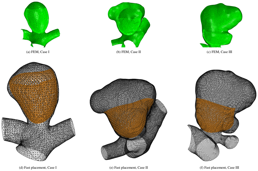
Summary. The paper develops a contact-resolved finite-element framework for simulating deployment of the Contour Neurovascular System (CNS) inside patient-specific intracranial aneurysm geometries. The device is modeled as a dual-layer, 144-wire Nitinol braid using geometrically exact Simo–Reissner beams; the vessel wall is a deformable Yeoh-type hyperelastic shell; wire–wire and wire–wall interactions are treated with regularized Coulomb friction; and release is applied through a staged, time-dependent protocol. Deployment metrics—contact area, pole displacement, neck coverage fraction η_cov, and largest uncovered gap g_max—are computed as outputs rather than prescribed. The framework is applied to three patient anatomies and compared qualitatively with an imaging-guided fast-placement reconstruction. The central claim is that CNS seating is a path-dependent contact problem in which friction and release depth dominate final morphology, and that geometric fast placement cannot capture the mechanically consistent equilibrium.
Significance. If the central claim were supported, the paper would address a genuine gap in computational treatment planning for intrasaccular flow disruptors: current CFD/FSI workflows usually prescribe a post-deployment geometry and thereby neglect the mechanics that determine neck coverage and apposition. The paper has real strengths: the use of beam–shell frictional contact with staged release is methodologically appropriate; the outputs are emergent from the equilibrium/contact problem rather than fitted to a target; the authors are explicit that wall and Nitinol parameters are bridge calibrations and that the three-case cohort is a transferability demonstration, not statistical validation. These honesty features are welcome. However, the predictive claim about friction and release depth as the dominant controls is currently not anchored to any quantitative comparison with observed implanted devices, and the device model is under-specified by missing braid and friction parameters. The significance is therefore conditional on a validation or a substantially narrowed claim.
major comments (4)
- [§2.1, §2.3, Fig. 8] The manuscript has post-treatment CTA for all three patients but uses it only to guide the fast-placement reconstructions; the FEM deployment is never compared quantitatively to the observed implanted device. Figure 8 compares FEM with fast placement, but fast placement is itself CTA-guided, so this only shows that the FEM differs from a CTA-informed visual fit. This is a load-bearing gap: the central claim that friction and release depth dominate seated morphology, and that the simulated geometry is 'patient-specific,' requires an external anchor. I ask the authors to add a quantitative comparison between the simulated seated state and the post-treatment CTA, e.g., pole position, centroid distance, neck coverage metrics (η_cov, g_max), or surface-distance errors. If such a comparison is not possible, the claims should be explicitly restricted to a simulation-internal demonstration.
- [§3.1, Eqs. (1)–(5), Table 2] The braid parametrization in Eqs. (1)–(5) contains seven parameters—A_r, W_r, p_r, A_w, W_w, p_w, and φ_i—that are never assigned numeric values. Table 1 gives only the wire count and nominal diameter. This makes the device model irreproducible and prevents assessing whether the simulated braid has a realistic stiffness, pore geometry, or crossover topology. Similarly, Table 2 reports only symbolic labels for the friction variants (p00, p11, p1d11, p3d13, p5d15, r near stick) with no numeric μ values, so the claimed 'useful regime' of friction is not quantitatively identified. Please provide the braid parameter values and the μ values used, or explicitly state that these are unknown and perform a sensitivity study over them.
- [§5, Table 1] The authors admit that the aneurysm wall and Nitinol parameters are bridge calibrations rather than device-specific bench-test identifications. This admission is honest, but it has consequences for the central claim. The quantitative outputs—contact area, η_cov, g_max, and the friction regime considered 'useful'—can shift if the true wall stiffness, superelastic response, or wire friction differ. Since post-treatment imaging data already exist, the missing validation is not merely a future step; it is an available test. I request either (a) a quantitative CTA-based comparison that would support the current claims, or (b) a deliberate reframing of the paper as a proof-of-concept on synthetic or phantom geometries, with the patient-specific cases treated only as illustrative. Without one of these, the statement that friction and release depth are 'the dominant controls' is stronger than th
- [§4.3 and Figures 6–7] The release-depth sweep is described as systematic, but no numerical release heights h are reported and no per-case values of the final metrics (η_cov, g_max, contact area) are given in a table. Figures 6 and 7 show history curves without quantitative axes labels in the text, making it difficult to assess the magnitude of the claimed effects. Please report the actual release heights and the resulting final metrics for each variant, at least for the baseline case, so the reader can see the effect size rather than only its qualitative direction.
minor comments (5)
- [Eq. (23)] The term 'equivalent (normalized) circular neck area' is unclear: A_neck,eq = L_neck^2/(4π) has units of area and is not normalized in the usual dimensionless sense. Please clarify the wording and, if normalization is intended, state the reference quantity.
- [Table 1] The Rayleigh damping entries are listed as 'α=10, β=10^-4' with units 's^-1, s', which is dimensionally inconsistent. Please check and provide the correct units or clarify that these are penalty-style numerical damping coefficients.
- [§1, last paragraph before §2] There is a typographical artifact in 'V ariationally consistent beam-beam coupling.' Please fix to 'Variationally.'
- [Data and code availability] The statement 'available from the corresponding author upon reasonable request' is weak for a computational mechanics paper. Since the framework depends on many parameters and patient geometries, archiving input files, mesh-generation scripts, and post-processing code in a permanent repository would substantially improve reproducibility.
- [Figures 4–7] The captions describe contact-area and pole-displacement histories, but the figure axes are not labeled in the text. Please ensure all subplots have explicit axis labels and units, and consider adding a legend identifying the friction variants directly on the plots.
Circularity Check
No significant circularity: deployed morphology is solved, not fitted; friction/release sweeps are sensitivity studies; fast placement is explicitly a qualitative comparator.
full rationale
The derivation chain is self-contained in the relevant sense. The braid parametrization of Eqs. (1)–(5) defines only the undeployed reference configuration, and the paper explicitly states that 'Equation (5) defines the reference braid before crimping and release. It does not prescribe the implanted geometry.' The deployed state is obtained by solving the mixed-dimensional structural/contact problem, Eqs. (6)–(20), with final metrics (η_cov, g_max, A_contact, u_tip) defined as post-processing functionals of the solved state (Eqs. (21)–(23)). No output quantity is a fitted version of an input, and no fitted parameter is renamed as a prediction. The friction/contact variants in Table 2 and the release-height variations are honest sensitivity sweeps: they are independent simulation parameters, and the reported history curves and final metrics are emergent outcomes. The only imaging-guided element, the fast-placement comparator, is manually fitted using post-treatment CTA, but the paper explicitly disclaims it as a mechanical solution ('it is not a (robust) mechanical solution...') and uses it only as a qualitative reference; it does not enter the FEM derivation or define the central quantitative claims. The acknowledged limitations — 'bridge calibrations' for wall/Nitinol parameters, a small cohort, and the absence of device-specific bench validation — concern external validity and predictive credibility, not circularity. Self-citations ([43]–[46], [48], [52]) are methodological building blocks (beam/surface coupling, beam-to-beam contact formulations) and are not used to justify the deployment results through an unverified uniqueness theorem or a smuggled ansatz. No specific equation can be exhibited that reduces any claimed prediction to its input by construction, so the appropriate finding is no significant circularity.
Assumptions & free parameters
free parameters (8)
- Yeoh wall coefficients C10, C20, C30 =
0.80 / 2.20 / 6.00 MPa
- Wall thickness t_wall =
0.50 mm
- Wall volumetric parameter D1 =
0.04 MPa^-1
- Rayleigh damping α, β =
10, 1e-4
- Nitinol superelastic parameters (EA, EM, ν, ε_tr, σ_Ls, σ_Lf, σ_Us, σ_Uf, σ_Ls,c) =
see Table 1
- Friction coefficient μ per variant =
p00=0 ... r≈near-stick
- Braid weave parameters A_r, W_r, p_r, A_w, W_w, p_w, phase offsets φ_i =
not reported
- Release height h =
varied systematically
assumptions (7)
- domain assumption Simo–Reissner geometrically exact beam theory adequately represents Nitinol wire mechanics including wire-wire contact at crossovers
- domain assumption Regularized penalty normal contact (Eqs. 14–15) with penalty stiffness ε_n and regularized Coulomb friction (Eqs. 16–18) capture wire-wire and wire-wall interaction
- domain assumption Auricchio superelastic constitutive law with Table 1 parameters describes the device Nitinol through crimping and release
- domain assumption Nearly incompressible homogeneous Yeoh shell with thickness 0.5 mm represents patient-specific aneurysm walls
- domain assumption The staged release protocol (imported preloaded state, approach, constrained blooming, final pole release; Eq. 20 Dirichlet control) reproduces clinical delivery mechanics
- domain assumption The parametric braid (Eqs. 1–5) reproduces the real Contour dual-layer architecture (2×72 wires) and its pore topology
- domain assumption Blood forces and wall prestress during deployment are negligible compared to structural/contact forces
Cite this review
Pith. "Pith review of Contact-resolved deployment of the Contour Neurovascular System in patient-specific intracranial aneurysms." pith.science (2026). https://pith.science/paper/UXQFYLNI
@misc{pith2026260713972,
  author       = {Pith},
  title        = {Pith review of: Contact-resolved deployment of the Contour Neurovascular System in patient-specific intracranial aneurysms},
  year         = {2026},
  howpublished = {\url{https://pith.science/paper/UXQFYLNI}},
  note         = {Machine review of arXiv:2607.13972}
}
read the original abstract
While intrasaccular flow disruptors are widely used to treat wide-neck intracranial aneurysms, state-of-the-art patient-specific computational models routinely neglect the deployment mechanics by prescribing a pre-seated geometry. This shortcut oversimplifies the true physics and misrepresents the Contour Neurovascular System (CNS), whose critical biomechanical features, such as neck coverage, wall apposition, and migration resistance, are highly path-dependent. To resolve this limitation, we present a contact-resolved finite-element framework that explicitly computes the structural mechanics of implant deployment within patient-specific vascular environments. The device is discretized as a dual-layer interwoven Nitinol braid using geometrically exact beams, while the vascular wall is represented as a deformable hyperelastic shell. Non-linear frictional contact formulations govern complex wire-wire and wire-wall interactions under a staged release protocol. Evaluating three anatomical phenotypes reveals that the final equilibrium morphology is highly sensitive to tangential slip resistance and vertical release depth. Frictionless assumptions permit excessive post-contact sliding, whereas near-stick conditions enhance anchoring but restrict local compliance. Crucially, conventional geometric fast placement fails to capture these critical contact interactions and wall-supported mechanical equilibrium. This deployment-resolved framework establishes a biomechanically grounded foundation for downstream hemodynamics, fluid-structure interaction, and mechanobiological thrombus-formation modeling.
Figures


Figures from the paper (5 more)


Reference graph
Works this paper leans on
-
[1]
Etminan, G
N. Etminan, G. J. Rinkel, Unruptured intracranial aneurysms: development, rupture and preventive manage- ment, Nature Reviews Neurology 12 (12) (2016) 699–713
2016
-
[2]
Backes, G
D. Backes, G. J. Rinkel, K. G. Laban, A. Algra, M. D. Vergouwen, Patient-and aneurysm-specific risk factors for intracranial aneurysm growth: a systematic review and meta-analysis, Stroke 47 (4) (2016) 951–957
2016
-
[3]
J. L. Brisman, J. K. Song, D. W. Newell, Cerebral aneurysms, New England Journal of Medicine 355 (9) (2006) 928–939
2006
-
[4]
Texakalidis, A
P. Texakalidis, A. Sweid, N. Mouchtouris, E. C. Peterson, C. Sioka, L. Rangel-Castilla, J. Reavey-Cantwell, P. Jab- bour, Aneurysm formation, growth, and rupture: the bi- ology and physics of cerebral aneurysms, World Neuro- surgery 130 (2019) 277–284
2019
-
[5]
D. C. Lauzier, A. L. Huguenard, A. I. Srienc, S. J. Cler, J. W. Osbun, A. R. Chatterjee, A. K. Vellimana, A. P. Kansagra, C. P. Derdeyn, D. T. Cross, A review of techno- logical innovations leading to modern endovascular brain aneurysm treatment, Frontiers in Neurology 14 (2023) 1156887. 8
2023
-
[6]
Fatania, T
K. Fatania, T. Patankar, Comprehensive review of the re- cent advances in devices for endovascular treatment of complex brain aneurysms, The British Journal of Radiol- ogy 95 (1129) (2022) 20210538
2022
-
[7]
R. M. Starke, C. R. Durst, A. Evans, D. Ding, D. M. Raper, M. E. Jensen, R. W. Crowley, K. C. Liu, Endovascular treat- ment of unruptured wide-necked intracranial aneurysms: comparison of dual microcatheter technique and stent- assisted coil embolization, Journal of NeuroInterventional Surgery 7 (4) (2015) 256–261
2015
-
[8]
Briganti, G
F. Briganti, G. Leone, M. Marseglia, G. Mariniello, F. Caranci, A. Brunetti, F. Maiuri, Endovascular treatment of cerebral aneurysms using flow-diverter devices: a sys- tematic review, The Neuroradiology Journal 28 (4) (2015) 365–375
2015
Show all 59 references
-
[9]
D. M. Heiferman, N. Goyal, V . Inoa, C. M. Nickele, A. S. Arthur, A new era in the treatment of wide necked bifur- cation aneurysms: intrasaccular flow disruption, Interven- tional Neuroradiology 30 (1) (2024) 31–36
2024
-
[10]
M. M. Shao, T. G. White, J. B. Bassett, E. Dowlati, S. H. Mehta, C. Werner, D. Golub, K. A. Shah, A. R. Dehdashti, I. Teron, Intrasaccular treatment of intracranial aneurysms: a comprehensive review, Journal of Clinical Medicine 13 (20) (2024) 6162
2024
-
[11]
Goubergrits, J
L. Goubergrits, J. Schaller, U. Kertzscher, T. Woelken, M. Ringelstein, A. Spuler, Hemodynamic impact of cere- bral aneurysm endovascular treatment devices: coils and flow diverters, Expert Review of Medical Devices 11 (4) (2014) 361–373
2014
-
[12]
S. F. Maroufi, M. S. Fallahi, M. Waqas, E. I. Levy, Com- parison between woven endobridge and coiling with and without stent assistance for intracranial bifurcation and wide-neck aneurysms: a comprehensive systematic review and meta-analysis, Journal of Neurosurgery 141 (4) (2...
2024
-
[13]
Dholakia, C
R. Dholakia, C. Sadasivan, D. J. Fiorella, H. H. Woo, B. B. Lieber, Hemodynamics of flow diverters, Journal of Biome- chanical Engineering 139 (2) (2017) 021002
2017
-
[14]
C. Wang, Z. Tian, J. Liu, L. Jing, N. Paliwal, S. Wang, Y . Zhang, J. Xiang, A. H. Siddiqui, H. Meng, Flow diverter effect of lvis stent on cerebral aneurysm hemodynamics: a comparison with enterprise stents and the pipeline device, Journal of Translational Medicine 14 (1) (2016) 199
2016
-
[15]
L. Jing, J. Zhong, J. Liu, X. Yang, N. Paliwal, H. Meng, S. Wang, Y . Zhang, Hemodynamic effect of flow di- verter and coils in treatment of large and giant intracranial aneurysms, World Neurosurgery 89 (2016) 199–207
2016
-
[16]
I. S. Muskens, J. T. Senders, H. H. Dasenbrock, T. R. Smith, M. L. Broekman, The woven endobridge device for treatment of intracranial aneurysms: a systematic review, World Neurosurgery 98 (2017) 809–817
2017
-
[17]
D. E. Mantilla, D. D. Vera, A. F. Ortiz, F. Nicoud, V . Costalat, The Woven EndoBridge device, an effective and safe alternative endovascular treatment of intracra- nial aneurysm: systematic review, Interventional Neu- roradiology (2023) 15910199231201544 doi:10.1177/ 15910199...
2023
-
[18]
Hecker, E
C. Hecker, E. Broussalis, J. A. Pfaff, S. Pikija, C. J. Griesse- nauer, M. Killer-Oberpfalzer, Comparison of the contour neurovascular system and woven endobridge device for treatment of wide-necked cerebral aneurysms at a bifurca- tion or sidewall, Journal of Neurosurgery 139...
2023
-
[19]
Wodarg, F
F. Wodarg, F. B. Neves, F. Gärtner, N. Larsen, S. Peters, J. Hensler, T. Klintz, J. Mahnke, H. Ahmeti, A. Doukas, Embolization of ruptured and unruptured aneurysms with the contour neurovascular system: summary of 106 cases, American Journal of Neuroradiology 46 (4) (2025) 698– 705
2025
-
[20]
Larsen, F
N. Larsen, F. Wodarg, J. Hensler, K. Mostafa, S. Peters, M. Pravdivtseva, S. Saalfeld, F. Gärtner, Morphological factors and device deformation associated with recurrence in intracranial aneurysms treated with the contour neurovas- cular system, Journal of Neuroradiology (2026) 101407
2026
-
[21]
C. Y . Akhunbay-Fudge, K. Deniz, A. K. Tyagi, T. Patankar, Endovascular treatment of wide-necked intracranial aneurysms using the novel contour neurovascular system: a single-center safety and feasibility study, Journal of Neu- roInterventional Surgery 12 (10) (2020) 987–992
2020
-
[22]
Bhogal, I
P. Bhogal, I. Lylyk, J. Chudyk, N. Perez, C. Bleise, P. Lylyk, The contour-early human experience of a novel aneurysm occlusion device, Clinical Neuroradiology 31 (2021) 147– 154
2021
-
[23]
C. J. Griessenauer, S. Ghozy, A. Biondi, C. Hecker, F. Wodarg, T. Liebig, T. Patankar, S. Lamin, M. Martínez- Galdámez, C. Cognard, Contour neurovascular system for endovascular embolization of cerebral aneurysms: a multi- center cohort study of 10 european neurovascular cente...
2025
-
[24]
O. Koc, M. Mahmoud, E. Mahmoud, A. Ayyad, A. Own, Delayed aneurysm rupture following endovascular treat- ment with contour device: a case report, Neurointervention (2025)
2025
-
[25]
M. Lyu, R. Torii, C. Liang, T. W. Peach, P. Bhogal, L. Makalanda, Q. Li, Y . Ventikos, D. Chen, Treatment for middle cerebral artery bifurcation aneurysms: in silico comparison of the novel contour device and conventional flow-diverters, Biomechanics and Modeling in Mechanobi-...
2024
-
[26]
Korte, F
J. Korte, F. Gaidzik, N. Larsen, E. Schütz, T. Damm, F. Wodarg, J.-B. Hövener, O. Jansen, G. Janiga, P. Berg, 9 et al., In vitro and in silico assessment of flow modula- tion after deploying the contour neurovascular system in intracranial aneurysm models, Journal of NeuroInte...
2024
-
[27]
Korte, F
J. Korte, F. Gaidzik, L. Spitz, M. S. Pravdivtseva, D. Behme, N. Larsen, S. Saalfeld, P. Berg, Analysis of the treatment effect of the contour neurovascular system in intracranial aneurysms: larger neck coverage area is associated with longitudinal flow reduction, Computers in...
2025
-
[28]
Spitz, J
L. Spitz, J. Korte, F. Gaidzik, N. Larsen, B. Preim, S. Saalfeld, Assessment of intracranial aneurysm neck deformation after contour deployment, International Jour- nal of Computer Assisted Radiology and Surgery 19 (12) (2024) 2321–2327
2024
-
[29]
Frank, F
M. Frank, F. Holzberger, M. Horvat, J. Kirschke, M. Mayr, M. Muhr, N. Nebulishvili, A. Popp, J. Schwart- ing, B. Wohlmuth, Numerical simulation of endovascu- lar treatment options for cerebral aneurysms, GAMM- Mitteilungen 47 (3) (2024) e202370007
2024
-
[30]
Abdehkakha, A
A. Abdehkakha, A. L. Hammond, T. R. Patel, A. H. Sid- diqui, G. F. Dargush, H. Meng, Cerebral aneurysm flow diverter modeled as a thin inhomogeneous porous medium in hemodynamic simulations, Computers in Biology and Medicine 139 (2021) 104988
2021
-
[31]
Berod, C
A. Berod, C. Chnafa, S. Mendez, F. Nicoud, A heteroge- neous model of endovascular devices for the treatment of intracranial aneurysms, International Journal for Numerical Methods in Biomedical Engineering 38 (2) (2022) e3552
2022
-
[32]
Reymond, G
P. Reymond, G. Bernava, O. Brina, J. Hofmeister, A. Rosi, K.-O. Lövblad, P. Machi, A novel method for brain aneurysms computed fluid dynamics analysis after flow diverter stent implantation based on micro-computed to- mography reconstruction, Journal of Biomechanics (2025) 112634
2025
-
[33]
P. Berg, S. Saalfeld, S. V oß, O. Beuing, G. Janiga, A review on the reliability of hemodynamic modeling in intracranial aneurysms: why computational fluid dynamics alone can- not solve the equation, Neurosurgical Focus 47 (1) (2019) E15
2019
-
[34]
Campo-Deaño, M
L. Campo-Deaño, M. S. Oliveira, F. T. Pinho, A re- view of computational hemodynamics in middle cerebral aneurysms and rheological models for blood flow, Applied Mechanics Reviews 67 (3) (2015) 030801
2015
-
[35]
M. A. Boniforti, G. Vittucci, R. Magini, Endovascular treatment of intracranial aneurysm: the importance of the rheological model in blood flow simulations, Bioengineer- ing 11 (6) (2024) 522
2024
-
[36]
J. H. Kim, T. J. Kang, W.-R. Yu, Mechanical modeling of self-expandable stent fabricated using braiding technology, Journal of Biomechanics 41 (15) (2008) 3202–3212. doi: 10.1016/j.jbiomech.2008.08.005
2008 doi
-
[37]
De Beule, S
M. De Beule, S. Van Cauter, P. Mortier, D. Van Loo, R. Van Impe, P. Verdonck, B. Verhegghe, Virtual opti- mization of self-expandable braided wire stents, Medical Engineering & Physics 31 (4) (2009) 448–453
2009
-
[38]
Kelly, D
N. Kelly, D. J. McGrath, C. A. Sweeney, K. Kurten- bach, J. A. Grogan, S. Jockenhoevel, B. J. O’Brien, P. E. McHugh, Comparison of computational modelling tech- niques for braided stent analysis, Computer Methods in Biomechanics and Biomedical Engineering 22 (16) (2019) 1334–1344
2019
-
[39]
C. G. McKenna, T. J. Vaughan, A finite element investi- gation on design parameters of bare and polymer-covered self-expanding wire braided stents, Journal of the Mechan- ical Behavior of Biomedical Materials 115 (2021) 104305
2021
-
[40]
Zaccaria, G
A. Zaccaria, G. Pennati, L. Petrini, Analytical methods for braided stents design and comparison with fea, Journal of the Mechanical Behavior of Biomedical Materials 119 (2021) 104560
2021
-
[41]
Abdollahi, A
R. Abdollahi, A. Shahi, D. Roy, S. Lessard, R. Mongrain, G. Soulez, Virtual and analytical self-expandable braided stent treatment models, Medical Engineering & Physics 126 (2024) 104145
2024
-
[42]
M. S. Pravdivtseva, A. N. Pravdivtsev, S. Peters, J. Hensler, N. Larsen, J.-B. H"ovener, O. Jansen, F. Wodarg, The effect of the size of the new Contour neurovascular device for altering intraaneurysmal flow, Interventional Neuroradiology 31 (1) (2025) 49–56. doi:10.1177/ 1591...
2025
-
[43]
Steinbrecher, N
I. Steinbrecher, N. Hagmeyer, C. Meier, A. Popp, A consistent mixed-dimensional coupling approach for 1d Cosserat beams and 2d surfaces in 3d space, Computational Mechanics 76 (5) (2025) 1233–1260. doi:10.1007/ s00466-025-02647-9
2025
-
[44]
A. Popp, I. Steinbrecher, Finite element formulations for beam-to-solid interaction: from embedded fibers towards contact, in: Current Trends and Open Problems in Compu- tational Mechanics, Springer, 2022, pp. 425–434
2022
-
[45]
Popp, State-of-the-art computational methods for fi- nite deformation contact modeling of solids and structures, Contact Modeling for Solids and Particles (2018) 1–86
A. Popp, State-of-the-art computational methods for fi- nite deformation contact modeling of solids and structures, Contact Modeling for Solids and Particles (2018) 1–86
2018
-
[46]
Steinbrecher, N
I. Steinbrecher, N. Hagmeyer, C. Meier, A. Popp, A varia- tionally consistent beam-to-beam point coupling formula- tion for geometrically exact beam theories, arXiv preprint arXiv:2604.02049 (2026).arXiv:2604.02049
2026 arXiv
-
[47]
Shiozaki, T
S. Shiozaki, T. Otani, S. Fujimura, H. Takao, S. Wada, Computational modeling of braided-stent deployment for interpreting the mechanism of stent flattening, International Journal for Numerical Methods in Biomedical Engineering 37 (12) (2021) e3335.doi:10.1002/cnm.3335. 10
2021 doi
-
[48]
Firmbach, I
M. Firmbach, I. Steinbrecher, A. Popp, M. Mayr, Com- putational challenges in mixed-dimensional beam/solid coupling, PAMM 23 (1) (2023) e202200227
2023
-
[49]
J. C. Simo, A finite strain beam formulation. the three- dimensional dynamic problem. part i, Computer Methods in Applied Mechanics and Engineering 49 (1) (1985) 55– 70
1985
-
[50]
J. C. Simo, L. Vu-Quoc, A three-dimensional finite-strain rod model. part I: Kinematics and constitutive equations, Computer Methods in Applied Mechanics and Engineering 58 (1) (1986) 79–116
1986
-
[51]
J. C. Simo, L. Vu-Quoc, On the dynamics in space of rods undergoing large motions: a geometrically exact approach, Computer Methods in Applied Mechanics and Engineering 66 (2) (1988) 125–161
1988
-
[52]
Meier, A
C. Meier, A. Popp, W. A. Wall, Geometrically exact finite element formulations for slender beams: Kirchhoff-love theory versus simo-reissner theory, Archives of Computa- tional Methods in Engineering 26 (1) (2019) 163–243
2019
-
[53]
Bazilevs, M.-C
Y . Bazilevs, M.-C. Hsu, Y . Zhang, S. Wang, T. Kvams- dal, S. Hentschel, J. G. Isaksen, Computational vascular fluid-structure interaction: methodology and application to cerebral aneurysms, Biomechanics and Modeling in Mechanobiology 9 (4) (2010) 481–498
2010
-
[54]
Torii, M
R. Torii, M. Oshima, T. Kobayashi, K. Takagi, T. E. Tezdu- yar, Fluid-structure interaction modeling of blood flow and cerebral aneurysm: significance of artery and aneurysm shapes, Computer Methods in Applied Mechanics and En- gineering 198 (45-46) (2009) 3613–3621
2009
-
[55]
Takizawa, T
K. Takizawa, T. Brummer, T. E. Tezduyar, P. R. Chen, A comparative study based on patient-specific fluid-structure interaction modeling of cerebral aneurysms, Journal of Applied Mechanics 79 (2012) 010908
2012
-
[56]
Raviol, G
J. Raviol, G. Plet, R. Hasegawa, K. Yu, H. Kosukegawa, M. Ohta, H. Magoariec, C. Pailler-Mattei, Towards the mechanical characterisation of unruptured intracranial aneurysms: numerical modelling of interactions between a deformation device and the aneurysm wall, Journal of the...
2024
-
[57]
Raviol, G
J. Raviol, G. Plet, J.-B. Langlois, S. Si-Mohamed, H. Magoariec, C. Pailler-Mattei, In vivo mechanical char- acterization of arterial wall using an inverse analysis pro- cedure: application on an animal model of intracranial aneurysm, Royal Society Open Science 11 (4) (2024) 231936
2024
-
[58]
Auricchio, R
F. Auricchio, R. L. Taylor, J. Lubliner, Shape-memory al- loys: macromodelling and numerical simulations of the superelastic behavior, Computer Methods in Applied Me- chanics and Engineering 146 (3-4) (1997) 281–312
1997
-
[59]
Elsisy, Y
M. Elsisy, Y . Chun, Materials properties and manufacturing processes of nitinol endovascular devices, in: Bio-materials and Prototyping Applications in Medicine, Springer, 2020, pp. 59–79. 11
2020
Reviewed August 2, 2026 · model on record in the stance chip above.
Discussion (0). Continue with ORCID to comment.