REVIEW 3 major objections 6 minor 27 references
Color-Coded Fiber-Optic Tactile Sensor for an Elastomeric Robot Skin
T0 review · 3 major / 6 minor · reviewed 2026-08-14 · deepseek-v4-flash
Pith's one-line read A silicone pad lit by red, green, and blue LEDs reports contact location and force through plastic optical fibers and a commodity camera.
desk verdict A clever color-coded optical skin with plausible classification results, but the headline resolution numbers are just the experimental quantization, not measured sensor properties. read the letter →
The pith
A machine-rendered reading of the paper's core claim, the machinery that carries it, and where it could break.
The reading
What carries the argument
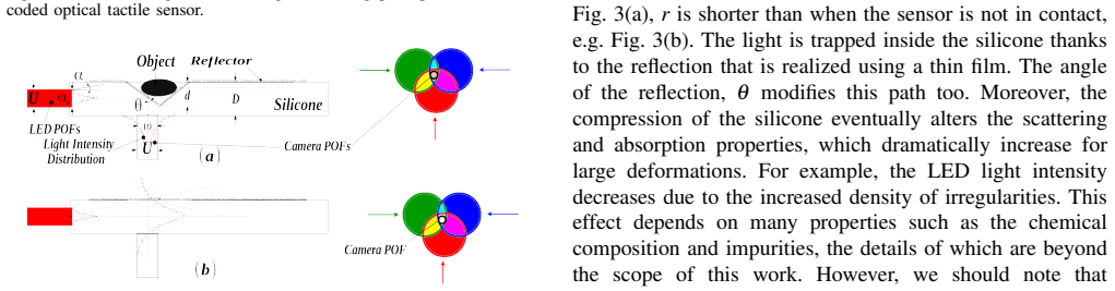
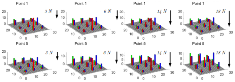
The load-bearing mechanism is color-coded light scattering in a compressible silicone waveguide. Three LEDs send red, green, and blue light into the pad through plastic optical fibers; an external force compresses the silicone, shortening or lengthening the light paths to the receiving fibers and changing the material's scattering and absorption, so the RGB balance of each received beam acts as a local pressure indicator. The readout is a 27-dimensional feature vector of per-fiber, per-channel mean intensities, and the estimator is a two-level hierarchical classifier: level one chooses the contact cell, level two chooses the depth. This separation of localization from depth estimation is what lifts the joint accuracy from 81.5% to 92.7%.
What would settle it
Press the indentor between two neighboring grid points, for example a 2.5 mm offset, and at depths that are not among 0.6, 1.2, 1.8, 2.4, and 3.0 mm, and compare the predicted position and force against ground truth: if errors exceed 8 mm or 3.6 N at those intermediate states, the reported resolutions are properties of the grid, not of the sensor.
Extended reading notes
Core claim
The core claim is that color itself can encode mechanical contact in an elastomer. A 40×40×5 mm silicone pad is molded with twelve plastic optical fibers: three deliver red, green, and blue light into the material, and nine carry the scattered mixture to a webcam. Pressing the pad changes the beam paths and the scattering and absorption inside the silicone, so each of the nine receiving fibers shows a different color shift. Averaging the red, green, and blue values over the nine fiber regions yields a 27-dimensional feature vector. The paper trains classical classifiers on this vector and finds that a hierarchical k-nearest-neighbor scheme, which first localizes the contact to one of 25 grid cells (99.2% test accuracy) and then estimates the depth among five levels (93.5%), reaches 92.7% combined accuracy, well above the 81.5% of a flat 125-class classifier. From these discrete levels the paper derives a force sensing range up to 18 N, a force resolution around 3.6 N, and a spatial resolution of 8 mm.
Load-bearing premise
The 8 mm spatial resolution and 3.6 N force resolution are taken directly from the 5×5 contact grid and the five indentation depths, so the claim assumes those discrete samples faithfully stand in for continuous contact position and force.
Editorial extensions
If this is right
- A robot fingertip covered by this skin can know both where and how hard it is touched without any conductive element at the contact surface.
- Because the transducing medium is molded silicone and the detector is a commodity webcam, the complete sensor can be assembled from low-cost parts and replaced by re-molding.
- The optical readout is unaffected by magnetic fields and can be sealed against water, so the design fits robots in wet, dusty, or magnetically noisy environments.
- Localization alone is accurate enough (99.2%) for tactile exploration tasks, while force estimation is coarser and best used as a discrete pressure level.
- Hierarchical classification—locate first, then estimate depth—is a practical strategy for other soft optical skins that need joint position and force readings.
Reading between the lines
- Editorial inference: the 8 mm and 3.6 N resolution figures are quotients of the experimental grid (40 mm across five cells, 18 N across five depths), so they describe the training grid rather than a measured continuous resolution; a denser press test would likely report coarser effective resolution.
- Editorial inference: the color-mixing idea could scale to more illumination colors or to spectral encoding, raising the dimensionality of the descriptor without adding fibers and possibly improving depth discrimination beyond five levels.
- Editorial inference: the 15 Hz camera caps the sensor at quasi-static exploration; replacing it with a faster or event-based camera would likely extend the same sensing principle to slip detection and dynamic manipulation, which the paper does not demonstrate.
- Editorial inference: because the image-to-force map is learned per fabricated pad, the practical deployment of this skin would require either a calibration step for every new molding or a transfer-learning procedure; the paper does not test cross-pad generalization.
Signed reviews
Editorial analysis
A structured set of objections, weighed in public.
Referee Report
Summary. The paper describes a color-coded fiber-optic tactile sensor for robotic skin. The sensing element is a transparent silicone layer illuminated by red, green, and blue LEDs through plastic optical fibers, with a commodity camera capturing the resulting light patterns via nine additional fibers. The authors argue that placing all electronics away from the sensing surface improves robustness. A 27-dimensional feature vector (mean RGB values over nine fiber regions) is fed to standard classifiers (LDA, QDA, SVM, k-NN). The sensor was characterized using a UR10 robot pressing a 3 mm-radius dome indentor at 25 grid locations on a 40x40 mm surface, at five indentation depths (0.6 mm steps, up to 3 mm), with ten images per contact state, yielding a 33,750-sample dataset. The best flat classification accuracy is 81.55% (k-NN) over 125 classes, and a hierarchical scheme (localization then depth) raises accuracy to 92.7%. The abstract claims a force range up to 18 N, a force resolution of about 3.6 N, and a spatial resolution of 8 mm.
Significance. If the quantitative claims were substantiated, the sensor would be a useful contribution: simple construction, off-the-shelf camera, electronics remote from the contact surface, and a machine-learning-based decoding pipeline. The experiment is thoughtfully designed, the dataset is substantial, and the comparison of four classifiers with cross-validation and held-out testing reports is reproducible in principle. The hierarchical classification pipeline is a sensible way to exploit the structure of the problem. However, the headline resolution figures (3.6 N force resolution, 8 mm spatial resolution) are not supported by the experiments: they coincide exactly with the quantization of the experimental grid and depth levels, and no test measures the minimum distinguishable force change or spatial separation. As written, the abstract overstates the sensor's demonstrated capability.
major comments (3)
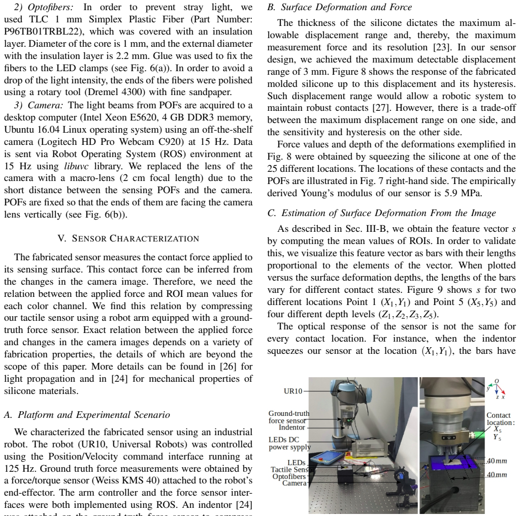
- [Sec. V-A and Abstract] The claimed force resolution of 3.6 N and spatial resolution of 8 mm are not measured. The experiment records only five discrete depth levels (0.6 mm steps) and 25 fixed grid locations (40 mm / 5 = 8 mm spacing). The reported values are exactly the quotients of the force range (18 N) and the sensor size (40 mm) by the number of levels and grid cells. No experiment presents a stimulus that would establish the minimum resolvable force difference or the minimum separable displacement, such as off-grid contact positions or force increments smaller than the step. The resolution numbers are therefore artifacts of the class-label design, not sensor properties.
- [Secs. V-D and V-E] The classification results (81.55% flat, 92.7% hierarchical) are measured only over the 125 discrete training states. They demonstrate that the sensor can distinguish those particular locations and depths, but not that it resolves continuous force or position. The paper's own hierarchical pipeline predicts one of 25 locations and one of five depths; the behavior of the system for contacts between grid points or between depth levels is untested and, given the 27-nearest-neighbor approach, likely to be poorly defined. The abstract's use of 'resolution' implies a minimum detectable increment, which requires a dedicated discrimination experiment (e.g., two-alternative forced choice or threshold measurement).
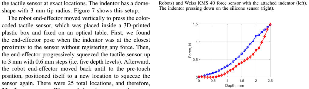
- [Secs. V-C and V-D] The force sensing claim is not established through a calibrated force estimate. The text states that the exact image-to-force relation 'depends on a variety of fabrication properties, the details of which are beyond the scope of this paper' (Sec. V). The experimental pipeline classifies indentation depth levels rather than regressing force, and the 18 N force range is only indirectly implied by the hysteresis plot in Fig. 8; the 18 N value is not derived or validated. To support 'force sensing range up to 18 N' and 'force resolution of 3.6 N', the authors should provide a force calibration curve with prediction error, or explicitly reduce the claims to 'force classification at five depth levels'.
minor comments (6)
- [Sec. V-B and Fig. 8] The hysteresis area is reported as '15 Nm'. For a 40x40 mm sensor this unit is almost certainly a typo (likely 'N·mm' or another unit for the area under the force-displacement curve); please correct it.
- [Fig. 3 caption] The caption contains a typo: 'no change of the light inensity' should read 'intensity'.
- [Sec. II-B] There is a typo: 'additon' should be 'addition'.
- [Sec. III-A] The phrase 'Youngs modulus' is missing an apostrophe: should be 'Young's modulus'.
- [Sec. V-E] The hierarchical accuracy of 92.7% appears to be the product of the localization accuracy (99.2%) and the depth accuracy (93.5%). Please state explicitly how the combined accuracy was computed and report the standard error or confidence interval.
- [Sec. III-A] The sentence 'Contact localization is possible thanks to the lower number of light sources compared to the number of camera POFs' is unclear; the mechanism by which fewer sources enables localization is not explained.
Circularity Check
The headline 3.6 N force resolution and 8 mm spatial resolution are exact quotients of the experimental design (18 N / 5 depth levels and 40 mm / 5 grid positions) and are never tested against continuous or off-grid stimuli; the classification accuracies are honest, but the resolution claims reduce by construction.
-
fitted input called prediction
[Abstract; Sec. V-A; Sec. V-B]
"We achieved a force sensing range up to 18 N with the force resolution of around 3.6 N and the spatial resolution of 8 mm. ... the robot end-effector progressively squeezed the tactile sensor up to 3 mm with 0.6 mm steps (i.e. five depth levels). ... The thickness of the silicone dictates the maximum allowable displacement range and, thereby, the maximum measurement force and its resolution [23]."
The reported force resolution of around 3.6 N is exactly 18 N divided by the five depth levels (18/5 = 3.6). No experiment measures the minimum distinguishable force change; all data come from five fixed indentation depths spanning the 18 N range. The abstract presents this quotient as an 'achieved' resolution, but it is forced by the chosen number of discrete depth classes, not by any minimum-separation test. The paper itself states that the exact image-to-force relation 'depends on a variety of fabrication properties, the details of which are beyond the scope of this paper,' so no analytical derivation supplies an independent resolution value.
-
fitted input called prediction
[Sec. V-A; Sec. V-D; Sec. V-E]
"There were 25 total locations, and therefore, 25×5 contact states. ... Number of classes is 125 due to 25 contact point locations and 5 depth levels of the indentor resulting in a 33750 sample dataset."
The spatial resolution of 8 mm is exactly the 40 mm sensor dimension divided by the five contact locations per axis (40/5 = 8). All experiments use only these 25 on-grid locations; no off-grid displacement is tested. The 92.7% hierarchical classification accuracy only shows separability of the 125 pre-defined discrete classes, not the ability to resolve arbitrary continuous positions. Thus the spatial-resolution claim is a restatement of the chosen grid spacing rather than an independently measured sensor capability.
full rationale
The paper's core classification results are genuine out-of-sample measurements: k-NN, SVM, QDA, LDA accuracies and the 92.7% hierarchical accuracy are computed on held-out trials and are not circular. However, the headline performance claims in the abstract are not independent empirical findings. With exactly five depth levels spanning the 18 N force range, the adjacent-class force step is 3.6 N by construction; with 25 locations on a 40 mm square, the adjacent-location spacing is 8 mm by construction. No experiment measures the smallest resolvable force increment or the smallest separable contact displacement, and all tests use only the pre-defined discrete states. Therefore the 'force resolution' and 'spatial resolution' are arithmetic reflections of the experimental design, not measured sensor properties. There is no load-bearing self-citation chain: references [23], [24], and [26] support generic material and optical relations, while the resolution claim is generated internally from the discrete protocol. Score 6 reflects partial circularity: the classification evaluation is honest, but the headline resolution metrics reduce by construction to the chosen quantization.
Assumptions & free parameters
free parameters (4)
- Empirically derived Young's modulus E =
5.9 MPa
- Force quantization step =
3.6 N over five depth levels
- Spatial grid spacing =
8 mm on a 40 mm sensor
- Machine learning hyperparameters =
Not reported (Matlab defaults)
assumptions (5)
- domain assumption The silicone substrate can be approximated by a spring with constant Young's modulus (F ∝ EA/D d).
- domain assumption Deformation changes the light scattering and absorption in the silicone in a way captured by the mean RGB values of the nine camera POFs.
- ad hoc to paper The 25 grid locations and five depth levels chosen for data collection are sufficient to characterize the sensor's continuous performance.
- domain assumption The classifier trained on data from 20 experimental trials generalizes to the 7 held-out trials from the same sensor and session.
- standard math Gaussian beam attenuation I(r) ∝ I0 exp(-2 r^2 / ω^2) describes light propagation to the camera POFs.
Cite this review
Pith. "Pith review of Color-Coded Fiber-Optic Tactile Sensor for an Elastomeric Robot Skin." pith.science (2026). https://pith.science/paper/XPIUWC24
@misc{pith2026190803687,
  author       = {Pith},
  title        = {Pith review of: Color-Coded Fiber-Optic Tactile Sensor for an Elastomeric Robot Skin},
  year         = {2026},
  howpublished = {\url{https://pith.science/paper/XPIUWC24}},
  note         = {Machine review of arXiv:1908.03687}
}
read the original abstract
The sense of touch is essential for reliable mapping between the environment and a robot which interacts physically with objects. Presumably, an artificial tactile skin would facilitate safe interaction of the robots with the environment. In this work, we present our color-coded tactile sensor, incorporating plastic optical fibers (POF), transparent silicone rubber and an off-the-shelf color camera. Processing electronics are placed away from the sensing surface to make the sensor robust to harsh environments. Contact localization is possible thanks to the lower number of light sources compared to the number of camera POFs. Classical machine learning techniques and a hierarchical classification scheme were used for contact localization. Specifically, we generated the mapping from stimulation to sensation of a robotic perception system using our sensor. We achieved a force sensing range up to 18 N with the force resolution of around 3.6~N and the spatial resolution of 8~mm. The color-coded tactile sensor is suitable for tactile exploration and might enable further innovations in robust tactile sensing.
Figures


Figures from the paper (6 more)



Reference graph
Works this paper leans on
-
[1]
The brain uses extrasomatic in- formation to estimate limb displacement,
A. V . Terekhov and V . Hayward, “The brain uses extrasomatic in- formation to estimate limb displacement,” Proceedings of the Royal Society of London B: Biological Sciences , vol. 282, no. 1814, 2015
work page 2015
-
[2]
In pursuit of safety: An open-source library for physical human-robot interaction,
B. Navarro, et al. , “In pursuit of safety: An open-source library for physical human-robot interaction,” IEEE Robotics Automation Magazine, vol. 25, no. 2, pp. 39–50, June 2018
work page 2018
-
[3]
Tactile sensing in dexterous robot hands: Review,
Z. Kappassov, J.-A. Corrales, and V . Perdereau, “Tactile sensing in dexterous robot hands: Review,” Robotics and Autonomous Systems , vol. 74, pp. 195 – 220, 2015
work page 2015
-
[4]
Robotic tactile perception of object properties: A review,
S. Luo, et al. , “Robotic tactile perception of object properties: A review,”Mechatronics, vol. 48, pp. 54 – 67, 2017
work page 2017
-
[5]
The TacTip Family: Soft optical tactile sensors with 3D-printed biomimetic morphologies,
B. Ward-Cherrier, et al. , “The TacTip Family: Soft optical tactile sensors with 3D-printed biomimetic morphologies,” Soft Robotics , vol. 5, no. 2, pp. 216–227, 2018
work page 2018
-
[6]
B. Gates, “A robot in every home,” Scientific American, vol. 296, no. 1, pp. 58–65, 2007
work page 2007
-
[7]
Perceiving and reasoning about liquids using fully convolutional networks,
C. Schenck and D. Fox, “Perceiving and reasoning about liquids using fully convolutional networks,” The International Journal of Robotics Research, vol. 37, no. 4-5, pp. 452–471, 2018
work page 2018
-
[8]
The ocean one hands: An adaptive design for robust marine manipulation,
H. Stuart, et al., “The ocean one hands: An adaptive design for robust marine manipulation,”The International Journal of Robotics Research, vol. 36, no. 2, pp. 150–166, 2017
work page 2017
Show all 27 references
-
[9]
Towards a fine-manipulation system with tactile feedback for deep-sea environments,
P. Kampmann and F. Kirchner, “Towards a fine-manipulation system with tactile feedback for deep-sea environments,” Robotics and Au- tonomous Systems, vol. 67, pp. 115 – 121, May 2015
2015
-
[10]
Magnetic resonance-compatible tactile force sensor using fiber optics and vision sensor,
H. Xie, et al. , “Magnetic resonance-compatible tactile force sensor using fiber optics and vision sensor,” IEEE Sensors Journal , vol. 14, no. 3, pp. 829–838, Mar 2014
2014
-
[11]
Integration of fiber-optic sensor arrays into a multi-modal tactile sensor processing system for robotic end- effectors,
P. Kampmann and F. Kirchner, “Integration of fiber-optic sensor arrays into a multi-modal tactile sensor processing system for robotic end- effectors,” Sensors, vol. 14, no. 4, pp. 6854–6876, 2014
2014
-
[12]
Gelsight: High-resolution robot tactile sensors for estimating geometry and force,
W. Yuan, S. Dong, and E. H. Adelson, “Gelsight: High-resolution robot tactile sensors for estimating geometry and force,” Sensors, vol. 17, no. 12, 2017
2017
-
[13]
Responsive hydrogels for label-free signal transduc- tion within biosensors,
K. Gawel, et al., “Responsive hydrogels for label-free signal transduc- tion within biosensors,” Sensors, vol. 10, pp. 4381–4409, 2010
2010
-
[14]
Low cost plastic optical fiber pressure sensor embedded in mattress for vital signal monitoring,
D. Sartiano and S. Sales, “Low cost plastic optical fiber pressure sensor embedded in mattress for vital signal monitoring,” Sensors, vol. 17, no. 12, 2017
2017
-
[15]
Stretchable optomechanical fiber sensors for pressure determination in compressive medical textiles,
J. D. Sandt, et al. , “Stretchable optomechanical fiber sensors for pressure determination in compressive medical textiles,” Advanced Healthcare Materials, p. 1800293, Aug 2018
2018
-
[16]
ViTac: Feature sharing between vision and tactile sens- ing for cloth texture recognition,
S. Luo, et al., “ViTac: Feature sharing between vision and tactile sens- ing for cloth texture recognition,”2018 IEEE International Conference on Robotics and Automation (ICRA) , vol. abs/1802.07490, pp. 2722– 2727, 2018
2018 arXiv
-
[17]
Dual-modal tactile perception and exploration,
N. Pestell, et al. , “Dual-modal tactile perception and exploration,” IEEE Robotics and Automation Letters , vol. 3, pp. 1033–1040, 2018
2018
-
[18]
Slip detection with a biomimetic tactile sensor,
J. W. James, N. Pestell, and N. F. Lepora, “Slip detection with a biomimetic tactile sensor,” IEEE Robotics and Automation Letters , vol. 3, no. 4, pp. 3340–3346, Oct 2018
2018
-
[19]
Object exploration and manipulation using a robotic finger equipped with an optical three-axis tactile sensor,
M. Ohka, et al., “Object exploration and manipulation using a robotic finger equipped with an optical three-axis tactile sensor,” Robotica, vol. 27, no. 5, pp. 763–770, 2009
2009
-
[20]
Finger-shaped gelforce: Sensor for measuring surface traction fields for robotic hand,
K. Sato, et al., “Finger-shaped gelforce: Sensor for measuring surface traction fields for robotic hand,” IEEE Transactions on Haptics, vol. 3, no. 1, pp. 37–47, Jan 2010
2010
-
[21]
Change of the refractive index in an optical fiber due to externalforces,
K. Nagano, S. Kawakami, and S. Nishida, “Change of the refractive index in an optical fiber due to externalforces,”Applied Optics, vol. 17, no. 13, pp. 2080–2085, Jul 1978
1978
-
[22]
Precise shape reconstruction by active pattern in total-internal-reflection-based tactile sensor,
S. Saga, R. Taira, and K. Deguchi, “Precise shape reconstruction by active pattern in total-internal-reflection-based tactile sensor,” IEEE Transactions on Haptics , vol. 7, no. 1, pp. 67–77, Jan 2014
2014
-
[23]
Integrated proximity, contact and force sensing using elastomer-embedded commodity proximity sensors,
R. Patel, R. Cox, and N. Correll, “Integrated proximity, contact and force sensing using elastomer-embedded commodity proximity sensors,” Autonomous Robots, Apr 2018
2018
-
[24]
Durometer hardness and the stress-strain behavior of elastomeric materials,
H. J. Qi, K. Joyce, and M. C. Boyce, “Durometer hardness and the stress-strain behavior of elastomeric materials,” Rubber Chemistry and Technology, vol. 76, no. 2, pp. 419–435, 2003
2003
-
[25]
Optimization of a pneumatic balloon tactile display for robot-assisted surgery based on human perception,
C. H. King, et al. , “Optimization of a pneumatic balloon tactile display for robot-assisted surgery based on human perception,” IEEE Transactions on Biomedical Engineering , vol. 55, no. 11, pp. 2593– 2600, Nov 2008
2008
-
[26]
A new fabrication method for all-PDMS waveguides,
Z. Cai, et al., “A new fabrication method for all-PDMS waveguides,” Sensors and Actuators A: Physical , vol. 204, pp. 44 – 47, 2013
2013
-
[27]
A series elastic tactile sensing array for tactile exploration of deformable and rigid objects,
Z. Kappassov, et al., “A series elastic tactile sensing array for tactile exploration of deformable and rigid objects,” in 2018 IEEE/RSJ International Conference on Intelligent Robots and Systems (IROS) , Oct 2018, pp. 520–525
2018
Reviewed August 14, 2026 · model on record in the stance chip above.
Discussion (0). Continue with ORCID to comment.