REVIEW 3 major objections 7 minor 18 references
125-211 GHz Low Noise MMIC Amplifier Design for Radio Astronomy
T0 review · 3 major / 7 minor · reviewed 2026-08-14 · deepseek-v4-flash
Pith's one-line read A simulated HEMT amplifier achieves under 58 K noise across the 125–211 GHz band, a span now served only by SIS mixers.
desk verdict A competent simulation-only LNA design that hits the noise spec on paper but misses gain by 15 dB, and the proposed cascade fix is never simulated. read the letter →
The pith
A machine-rendered reading of the paper's core claim, the machinery that carries it, and where it could break.
The reading
What carries the argument
The argument is carried by a four-stage, common-source cascade of two-finger, 10 µm gate-width transistors in a 35 nm InP HEMT process. The first two stages are noise-optimized and the last two are optimized for flat gain and low output reflection; this staging works because the Friis cascaded noise equation makes the noise of later stages negligible once the early stages provide enough gain. Passive matching networks and bias lines are microstrip structures verified with electromagnetic simulation, and the claim of unconditional stability rests on the Rollett stability factor remaining above 7 from 0 to 400 GHz.
What would settle it
Fabricate the MMIC and measure its noise temperature and S-parameters on a 20 K cryostat across 125–211 GHz; the central claim fails if any measured noise point exceeds 58 K, if the band average exceeds 38.8 K beyond measurement uncertainty, or if the gain departs from 20.5 ± 0.85 dB by more than the test error.
Extended reading notes
Core claim
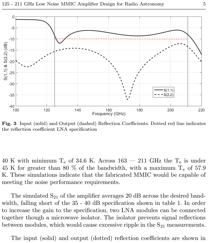
The central discovery is a simulated MMIC LNA that covers 125–211 GHz in one continuous band. At a physical temperature of 20 K, its simulated noise temperature stays below 58 K across the entire band, with a minimum of 34.6 K, a maximum of 57.9 K, and an average of 38.8 K; its forward gain is 20.5 ± 0.85 dB; input and output reflections are better than −6 dB and −12 dB, respectively; and the Rollett stability factor exceeds 7, so the amplifier is unconditionally stable. The design satisfies the stated noise specification for both sub-bands, but gain falls short of the 35–40 dB target, so two modules connected through an isolator would be needed to reach the full specification. The authors attribute the plausibility of these numbers to a prior W-band LNA in the same process that showed close agreement between simulation and measurement.
Load-bearing premise
Every simulated number depends on the proprietary transistor model and the electromagnetic simulation of the matching networks being as accurate at 125–211 GHz and 20 K as they were for the W-band design that validated them; no in-band measurement exists yet.
Editorial extensions
If this is right
- A single 15 K LNA cartridge could replace two 4 K SIS receiver cartridges covering 125–211 GHz, simplifying cryogenics and freeing a receiver slot.
- Connecting two amplifier modules through a microwave isolator brings the gain up to the specified 35–40 dB while preserving the noise and stability properties.
- The full 86 GHz of instantaneous bandwidth would let one receiver observe both sub-bands at once, enabling spectral-line surveys that currently require two separate tunings.
- If the fabricated part tracks the simulation, the result demonstrates that HEMT front-ends can match SIS mixer noise performance up to at least 211 GHz, challenging the superconducting receivers' hold on this range.
Reading between the lines
- Because the same 35 nm InP process has already produced amplifiers beyond 270 GHz, the 125–211 GHz design looks like an intermediate step; if the noise model holds, similar four-stage designs should reach higher sub-millimetre windows without changing technology.
- A complete receiver built around this LNA will have a higher system noise temperature than the 58 K amplifier figure once feedhorn, polariser and optics noise are added, so the paper's result is a front-end claim; the fair end-to-end comparison to SIS receivers remains to be measured.
- The simulated noise temperature peaks at 57.9 K in the 163–211 GHz sub-band, only about 1 K below the headline 58 K; testing fabricated devices densely across that sub-band is the fastest way to see whether the model's margin is real.
Signed reviews
Editorial analysis
A structured set of objections, weighed in public.
Referee Report
Summary. The paper presents a simulation-only design study of a four-stage 35-nm InP HEMT MMIC low-noise amplifier intended to cover the 125–211 GHz range, combining ALMA Bands 4 and 5. The authors report a simulated noise temperature below 58 K across the full band (average 38.8 K), a forward gain of 20.5 ± 0.85 dB, input/output reflection coefficients better than −6/−12 dB, reverse isolation better than −47 dB, and a Rollett stability factor above 7. They propose that two such modules, connected through an isolator, could meet the 35–40 dB gain specification in the ESO target specification. The central claim is that the simulated noise performance satisfies the specification and that a fabricated MMIC would be capable of meeting the noise requirements, challenging the dominance of SIS mixers in this frequency range. No measured results are presented; the design is scheduled for a future wafer run.
Significance. If the simulated noise performance were confirmed in a fabricated device, this design would be a significant step toward an LNA-based front-end covering ALMA Bands 4 and 5, potentially reducing cryogenic complexity and operational cost relative to SIS mixers. The explicit use of an externally defined specification (Table 1) and the detailed description of the MMIC topology are strengths, as is the recognition that a complete receiver must include feed, OMT, and optics noise contributions. The paper's contribution, however, is currently a simulation prediction with no measured verification and no uncertainty quantification; its significance therefore depends entirely on the trustworthiness of the proprietary transistor model at 125–211 GHz and of the electromagnetic simulations of the matching networks. The authors also claim to 'satisfy' the specification while falling short on gain and input match, which undermines the stated conclusion. With appropriate hedging and additional validation or explicit simulation-only framing, the design study could be a useful contribution to the millimeter-wave receiver community.
major comments (3)
- [Section 3 and Conclusion] The manuscript states that the MMIC 'satisfies' the LNA specification of Table 1, but the simulated forward gain of 20.5 ± 0.85 dB does not meet the required 35–40 dB, and the simulated input reflection coefficient of −6 dB does not meet the required < −10 dB. The proposed remedy of cascading two modules through an isolator is not simulated, so the cascade's gain, noise, input match, and stability remain unverified. The claims should be restricted to the noise-temperature portion of the specification, or the cascade must be designed and simulated before claiming overall specification compliance.
- [Sections 2 and 3] The central noise-temperature result (Te < 58 K, average 38.8 K) rests entirely on the proprietary 35-nm InP HEMT model at 125–211 GHz and on Momentum electromagnetic simulations of the passive networks, with no in-band measured verification. The only cited validation is the prior W-band design [9] at 67–116 GHz, a different frequency range and bias condition; the model card and any noise-parameter validation are not shown. Since the noise claim is the paper's central load-bearing contribution, the authors should provide measured validation, a quantitative model-uncertainty estimate (e.g., process corners or Monte Carlo), or explicitly frame the result as an unvalidated simulation prediction rather than a demonstrated capability.
- [Section 3] The statement that the stability factor is greater than 7 at all frequencies from 0 to 400 GHz is not substantiated by a plot or numerical table, and the definition of the stability factor (Rollett K or μ) is not given in Section 3. Given that the amplifier is four-stage with independent bias lines, a claim of unconditional stability over that entire range requires detailed out-of-band and bias-variation checks; as written, the claim is unverifiable from the manuscript.
minor comments (7)
- [Abstract] The phrase 'To the authors knowledge' is missing an apostrophe; it should read 'To the authors' knowledge'.
- [Section 1] The sentence 'Advances in HEMT technology have produced that LNAs are able to operate' is ungrammatical; it should be revised to something like 'Advances in HEMT technology have produced LNAs that are able to operate'.
- [Section 1] The text uses 'LNA’s' with an apostrophe in 'using LNA’s at higher frequencies'; the correct plural is 'LNAs'.
- [Section 3] The paper reports S21 as '20.5 ± 0.85 dB' in the abstract and Section 3, but later says the S21 'averages 20 dB'; these numbers should be reconciled for consistency.
- [Figure 2 caption] The caption states 'Dotted blue and red lines indicate the 80 and 100 % noise temperature LNA specifications' but does not specify which color corresponds to which sub-band (125–163 GHz versus 163–211 GHz), whose 80% and 100% requirements differ; this should be made explicit.
- [Acknowledgements] The name 'Northrup Grumann Corporation' is misspelled; it should be 'Northrop Grumman Corporation'.
- [Section 2] The phrase 'two-finger devices with gate width of 10 µm' is ambiguous; it should specify whether 10 µm is the width per finger or the total gate width of the device.
Circularity Check
No circularity: the simulated noise and gain results are forward outputs of the foundry device model and EM simulation, not fitted to the target specification.
full rationale
The paper's derivation chain is a conventional forward MMIC design flow: choose a foundry 35 nm InP HEMT model, design four common-source stages, simulate passive networks with Momentum, and report ADS noise/gain S-parameters. The claimed Te < 58 K, average 38.8 K, and S21 = 20.5 ± 0.85 dB are outputs of that simulation; no parameter is fitted to the 125–211 GHz noise specification or to any measured data in this band. The only self-referential element is the sentence 'Previous results from this process indicate that the measured performance matches the simulated performance closely [9]', citing the authors' prior W-band LNA. That citation is independent supporting evidence (measured S-parameters and noise at 67–116 GHz) rather than an input that defines the present Te values, so it does not make the derivation circular. The paper also explicitly labels the results as simulations and states 'This MMIC will be included on a future wafer run, and will be cryogenically tested to verify simulation results,' which is a stated limitation rather than a hidden reuse of the target result. The quantum-limit comparison is only a normalization of the simulated Te. The main weaknesses—extrapolation of the proprietary device model above W-band, unverified EM passive loss, gain below the 35–40 dB spec, and the two-module cascade proposed but not simulated—are correctness or risk concerns, not circularity.
Assumptions & free parameters
free parameters (3)
- Transistor gate width =
10 µm
- Physical temperature for simulation =
20 K
- Matching network component values =
not reported
assumptions (3)
- domain assumption The 35 nm InP HEMT foundry model accurately predicts cryogenic noise and gain at 125 to 211 GHz.
- domain assumption The passive matching networks are accurately modeled by Momentum EM simulation.
- standard math Friis cascade formula is applicable.
Cite this review
Pith. "Pith review of 125-211 GHz Low Noise MMIC Amplifier Design for Radio Astronomy." pith.science (2026). https://pith.science/paper/XY35KCZT
@misc{pith2026190800466,
  author       = {Pith},
  title        = {Pith review of: 125-211 GHz Low Noise MMIC Amplifier Design for Radio Astronomy},
  year         = {2026},
  howpublished = {\url{https://pith.science/paper/XY35KCZT}},
  note         = {Machine review of arXiv:1908.00466}
}
read the original abstract
To achieve the low noise and wide bandwidth required for millimeter wavelength astronomy applications, superconductor-insulator-superconductor (SIS) mixer based receiver systems have typically been used. This paper investigates the performance of high electron mobility transistor (HEMT) based low noise amplifiers (LNAs) as an alternative approach for systems operating in the 125 - 211 GHz frequency range. A four-stage, common-source, unconditionally stable monolithic microwave integrated circuit (MMIC) design is presented using the state-of-the-art 35 nm indium phosphide HEMT process from Northrop Grumman Corporation. The simulated MMIC achieves noise temperature (Te) lower than 58 K across the operational bandwidth, with average Te of 38.8 K (corresponding to less than 5 times the quantum limit (hf/k) at 170 GHz) and forward transmission of 20.5 +/- 0.85 dB. Input and output reflection coefficients are better than -6 and -12 dB, respectively, across the desired bandwidth. To the authors knowledge, no LNA currently operates across the entirety of this frequency range. Successful fabrication and implementation of this LNA would challenge the dominance SIS mixers have on sub-THz receivers.
Figures
Reference graph
Works this paper leans on
-
[9]
Cuadrado-Calle et al., Broadband MMIC LNAs for ALMA Band 2+3 With Noise Temperature Below 28 K
D. Cuadrado-Calle et al., Broadband MMIC LNAs for ALMA Band 2+3 With Noise Temperature Below 28 K. IEEE Transactions on Microwave Theory and Techniques, vol. 65, no. 5, 1589-1597, (2017), doi: 10.1109/TMTT.2016.2639018
arXiv 2017
-
[1]
T. Mimura, Invention of High Electron Mobility Transistor (HEMT) and Contributions to Information and Communications Field. Fujitsu Scientific & Technical Journal, Vol. 54, No. 5, pp. 3 - 8, (2018)
work page 2018
-
[2]
T. Palacios, A. Chakraborty, S. Heikman, S. Keller, S. P. DenBaars and U. K. Mishra, AlGaN/GaN high electron mobility transistors with InGaN back-barriers. IEEE Electron Device Letters, vol. 27, no. 1, pp. 13-15, Jan. 2006. doi: 10.1109/LED.2005.860882
-
[3]
J-H. Lee, H-S. Yoon, C-S. Park and H-M. Park, Ultra low noise characteristics of Al- GaAs/InGaAs/GaAs pseudomorphic HEMT’s with wide head T-shaped gate. IEEE Elec- tron Device Letters, vol. 16, no. 6, pp. 271-273, June 1995. doi: 10.1109/55.790732
-
[4]
Claude et al., The Band 3 receiver (84-116 GHz) for ALMA
S. Claude et al., The Band 3 receiver (84-116 GHz) for ALMA. 2005 Joint 30th In- ternational Conference on Infrared and Millimeter Waves and 13th International Con- ference on Terahertz Electronics, Williamsburg, VA, USA, 2005, pp. 407-408 vol. 2. doi: 10.1109/ICIMW.2005.1572585
-
[5]
Fujii et al., The First Six ALMA Band 10 Receivers
Y. Fujii et al., The First Six ALMA Band 10 Receivers. IEEE Transactions on Terahertz Science and Technology, vol. 3, no. 1, pp. 39-49, Jan. 2013. doi: 10.1109/TTHZ.2012.2236147
-
[6]
D. Cuadrado-Calle, D. George, B. Ellison, G. A. Fuller, K. Cleary, Celestial Signals: Are Low-Noise Amplifiers the Future for Millimeter-Wave Radio Astronomy Receivers?. IEEE Microwave Magazine, Vol. 18, no. 6, 90 -99, (2017), doi: 10.1109/MMM.2017.2712038
-
[7]
Suemitsu, InP and GaN High Electron Mobility Transistors for Millimeter- wave Applications
T. Suemitsu, InP and GaN High Electron Mobility Transistors for Millimeter- wave Applications. IEICE Electronics Express, Vol. 12, No. 13, 1-12, (2015), doi: 10.1587/elex.12.20152005
Show all 18 references
-
[8]
E. W. Byerton, M. Morgan, M. W. Pospieszalski, Ultra Low Noise Cryogenic Amplifiers for Radio Astronomy. 2013 IEEE Radio and Wireless Symposium, Austin, TX, USA, doi: 10.1109/RWS.2013.6486740
2013
-
[10]
Asayama et al, Development of ALMA Band 4 (125 - 163 GHz) receiver
S. Asayama et al, Development of ALMA Band 4 (125 - 163 GHz) receiver. Pub- lications of the Astronomical Society of Japan, Volume 66, Issue 3, June 2014, 57, https://doi.org/10.1093/pasj/psu026
2014 doi
-
[11]
Belitsky et al, ALMA Band 5 receiver cartridge - Design, performance, and commis- sioning
V. Belitsky et al, ALMA Band 5 receiver cartridge - Design, performance, and commis- sioning. Astronomy and Astrophysics, Vol. 611, 2018, doi: 10.1051/0004-6361/201731883
2018 doi
-
[12]
X. B. Mei et al., 35nm InP HEMT For Millimeter and Sub-Millimeter Wave Applica- tions. 2007 International Conference in Indium Phosphide and Related Materials Confer- ence Proceedings, vol. 19, 59 - 62, (2007)
2007
-
[13]
Varonen et al., 160-270-GHz InP HEMT MMIC Low-Noise Amplifiers
M. Varonen et al., 160-270-GHz InP HEMT MMIC Low-Noise Amplifiers. 2012 IEEE Compound Semiconductor Integrated Circuit Symposium, La Jolla, CA, 2012, pp. 1-4, doi: 10.1109/CSICS.2012.6340058
2012
-
[14]
Fung et al., Low Noise Amplifier Modules from 220-270 GHz
A. Fung et al., Low Noise Amplifier Modules from 220-270 GHz. 2013 European Mi- crowave Integrated Circuit Conference, Nuremberg, 2013, pp. 224-227. 8 Daniel White 1,2 et al
2013
-
[15]
P. V. Larkoski et al., Low Noise Amplifiers for 140 GHz Wide-Band Cryogenic Receivers. 2013 IEEE MTT-S International Microwave Symposium Digest (MTT), Seattle, WA, 2013, pp. 1-4. doi: 10.1109/MWSYM.2013.6697674
2013
-
[16]
Varonen et al., A WR4 Amplifier Module Chain With an 87 K Noise Temperature at 228 GHz
M. Varonen et al., A WR4 Amplifier Module Chain With an 87 K Noise Temperature at 228 GHz. in IEEE Microwave and Wireless Components Letters, vol. 25, no. 1, pp. 58-60, Jan. 2015. doi: 10.1109/LMWC.2014.2369963
2015
-
[17]
https://literature.cdn.keysight.com/litweb/pdf/5988- 3326EN.pdf?id=921864 (2017)
Keysight, Advanced Design System. https://literature.cdn.keysight.com/litweb/pdf/5988- 3326EN.pdf?id=921864 (2017). Accessed 4 Sep. 2018
2017
-
[18]
H. T. Friis, Noise Figures of Radio Receivers. Proceedings of the IRE, Vol 32, No. 7, 419 - 422, (1944), doi: 10.1109/JRPROC.1944.232049
1944
Reviewed August 14, 2026 · model on record in the stance chip above.
Discussion (0). Continue with ORCID to comment.