Combustion Phasing Modelling and Control for Compression Ignition Engines with High Dilution and Boost Levels
Pith reviewed 2026-05-24 19:19 UTC · model grok-4.3
The pith
A simplified nonlinear model supports controllers that regulate diesel combustion phasing to within 0.5 CAD in five cycles.
A machine-rendered reading of the paper's core claim, the machinery that carries it, and where it could break.
Core claim
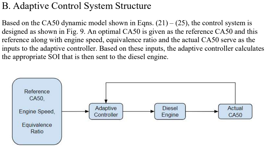
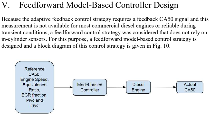
The combustion phasing model combines a knock integral model, burn duration model, and Wiebe function, simplified for control purposes and calibrated for high dilution and boost conditions. Based on this model, an adaptive nonlinear model-based controller for closed-loop control and a feedforward model-based controller for open-loop control are designed and tested in simulations, demonstrating rapid convergence and low steady-state errors for CA50.
What carries the argument
The simplified nonlinear combustion phasing model that integrates knock integral, burn duration, and Wiebe function elements to predict CA50 for controller design.
If this is right
- The model predicts CA50 accurately enough for control under high EGR and boost.
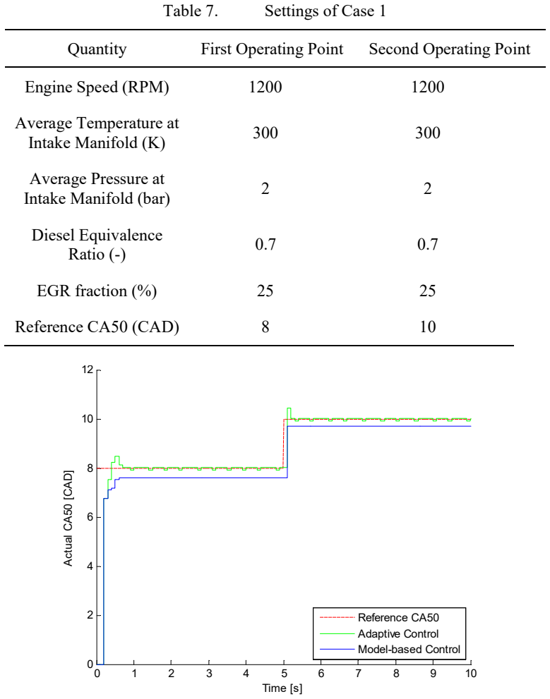
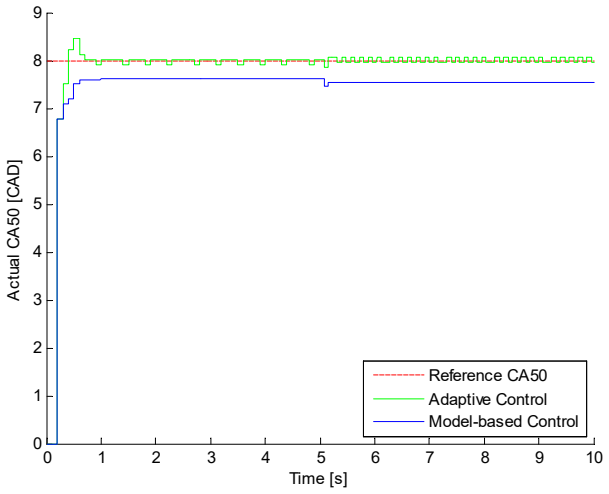
- Adaptive control achieves steady-state errors less than 0.1 CAD.
- Feedforward control achieves steady-state errors less than 0.5 CAD.
- Both controllers settle CA50 within 5 engine cycles during transients.
Where Pith is reading between the lines
- The control strategies might reduce the need for extensive calibration in production engines.
- Similar modeling could support control in other advanced combustion modes if recalibrated.
- Real-world testing would be needed to confirm performance beyond simulation.
Load-bearing premise
The simplified nonlinear model remains sufficiently accurate during unmeasured transients after calibration on available data.
What would settle it
Engine test data during transient operation where CA50 does not reach steady state within 5 cycles or exceeds the reported error bounds.
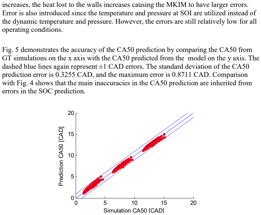
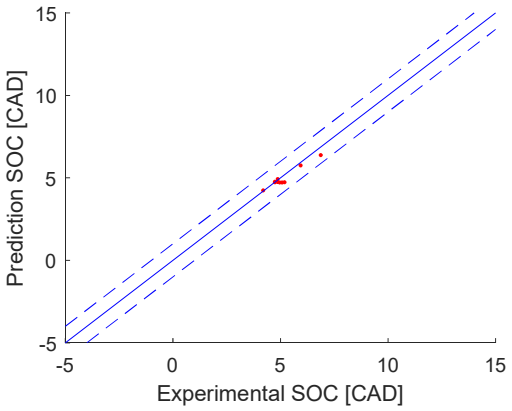
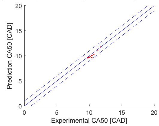
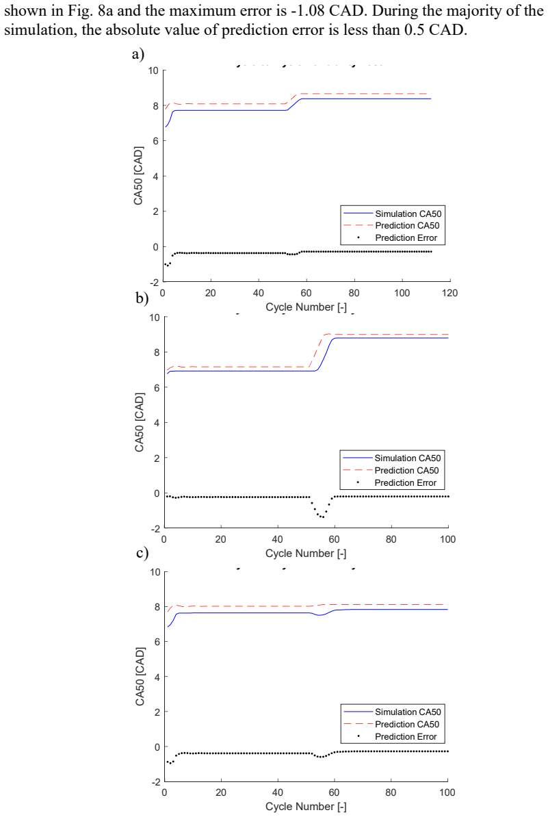
Figures

read the original abstract
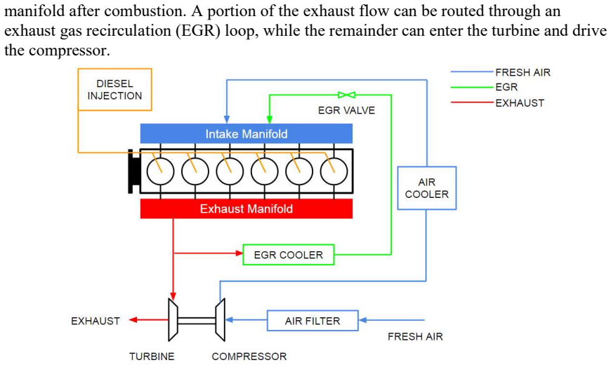
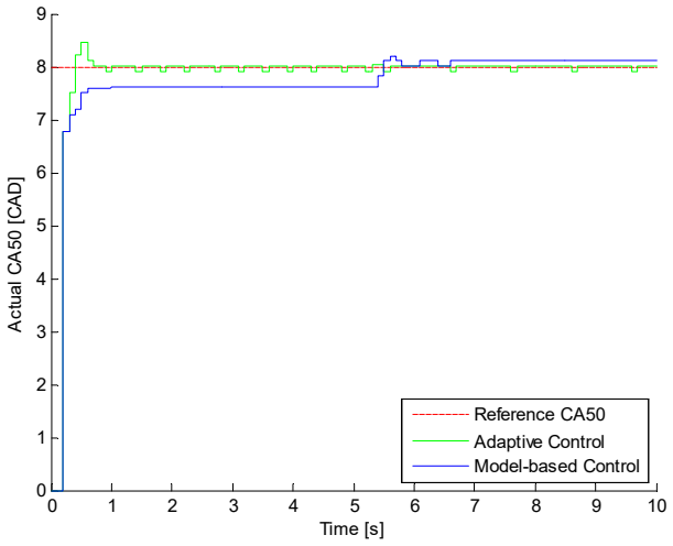
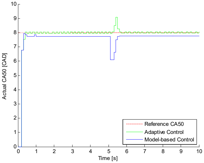
Because fuel efficiency is significantly impacted by the timing of combustion in internal combustion engines, accurate control of combustion phasing is critical. In this paper, a nonlinear combustion phasing model is introduced and calibrated, and both a feedforward model-based control strategy and an adaptive model-based control strategy are investigated for combustion phasing control. The combustion phasing model combines a knock integral model, burn duration model and a Wiebe function to predict the combustion phasing of a diesel engine. This model is simplified to be more suitable for combustion phasing control and is calibrated and validated using simulations and experimental data that include conditions with high exhaust gas recirculation fractions and high boost levels. Based on this model, an adaptive nonlinear model-based controller is designed for closed-loop control, and a feedforward model-based controller is designed for open-loop control. These two control approaches were tested in simulations. The simulation results show that during transient changes the CA50 (the crank angle at which 50% of the mass of fuel has burned) can reach steady state in no more than 5 cycles and the steady state errors are less than +/-0.1 crank angle degree (CAD) for adaptive control, and less than +/-0.5 CAD for feedforward model-based control.
Editorial analysis
A structured set of objections, weighed in public.
Referee Report
Summary. The paper introduces a simplified nonlinear combustion phasing model (knock integral + burn duration + Wiebe) for diesel engines at high EGR and boost levels. The model is calibrated on experimental data, then used to design a feedforward model-based controller and an adaptive nonlinear model-based controller for CA50. Both are evaluated only in simulation on the design model, where CA50 settles in ≤5 cycles with steady-state errors <±0.5 CAD (feedforward) and <±0.1 CAD (adaptive).
Significance. If the model remains accurate during unmeasured transients, the adaptive controller could provide a practical, low-error approach to combustion phasing under varying dilution and boost. The simulation metrics are quantitatively strong, but the absence of any reported transient model validation or closed-loop hardware results limits the immediate engineering significance.
major comments (2)
- [Abstract; simulation section] Abstract and simulation-results section: the headline claims (settling ≤5 cycles, errors <±0.1 CAD adaptive / <±0.5 CAD feedforward) are obtained by closing the loop on the identical calibrated model used for controller synthesis. No open-loop transient validation (measured vs. predicted CA50 during the boost/EGR steps) or closed-loop engine experiments are reported, so the metrics are not independent of the model assumptions.
- [Model calibration and validation] Model-calibration section: the manuscript states that the simplified model is “calibrated and validated using … experimental data,” yet no quantitative fit metrics (RMS CA50 error, R², or residual plots) are supplied for the transient conditions exercised by the controllers. This leaves the central assumption that the model remains sufficiently accurate during unmeasured fast transients untested.
minor comments (1)
- [Model equations] Notation for the knock-integral threshold and Wiebe shape parameters should be defined once at first use rather than re-introduced in the controller section.
Simulated Author's Rebuttal
We thank the referee for their thorough review and valuable comments. We address each major comment below with clarifications and indicate where revisions will be incorporated.
read point-by-point responses
-
Referee: [Abstract; simulation section] Abstract and simulation-results section: the headline claims (settling ≤5 cycles, errors <±0.1 CAD adaptive / <±0.5 CAD feedforward) are obtained by closing the loop on the identical calibrated model used for controller synthesis. No open-loop transient validation (measured vs. predicted CA50 during the boost/EGR steps) or closed-loop engine experiments are reported, so the metrics are not independent of the model assumptions.
Authors: We agree that the reported controller metrics are obtained from simulation closing the loop on the calibrated model used for synthesis. This is standard practice for initial verification of model-based controller designs. The underlying model was calibrated on experimental engine data at high EGR and boost levels. We will revise the abstract and simulation section to explicitly state that results are simulation-based on the design model and to note the absence of hardware closed-loop experiments as a limitation of the current study. revision: partial
-
Referee: [Model calibration and validation] Model-calibration section: the manuscript states that the simplified model is “calibrated and validated using … experimental data,” yet no quantitative fit metrics (RMS CA50 error, R², or residual plots) are supplied for the transient conditions exercised by the controllers. This leaves the central assumption that the model remains sufficiently accurate during unmeasured fast transients untested.
Authors: The calibration used experimental data at the relevant high-dilution and boost conditions. We acknowledge that explicit quantitative transient fit metrics (RMS error, R², residuals) for the specific boost/EGR steps are not reported. In the revised manuscript we will add these metrics and residual plots for the transient conditions to strengthen support for model accuracy during fast transients. revision: yes
- Closed-loop hardware experiments on the physical engine, which were not performed in this study.
Circularity Check
No significant circularity; model calibrated to external data with independent simulation testing
full rationale
The paper calibrates its nonlinear combustion phasing model (knock integral + burn duration + Wiebe) to experimental data under high EGR/boost conditions and reports separate validation. Controller performance metrics (CA50 settling ≤5 cycles, steady-state errors <±0.1 CAD adaptive / <±0.5 CAD feedforward) are obtained from closed-loop simulations on that model, which is standard model-based design practice and does not reduce any claimed result to the fitted constants by construction. No self-definitional equations, fitted-input predictions, or load-bearing self-citations appear in the derivation chain. The work remains self-contained against the external experimental benchmarks used for calibration/validation.
Axiom & Free-Parameter Ledger
free parameters (3)
- Knock-integral threshold and scaling constants
- Burn-duration coefficients
- Wiebe shape parameters
axioms (1)
- domain assumption The Wiebe function form accurately describes mass-fraction-burned profiles under the tested dilution and boost levels.
Reference graph
Works this paper leans on
-
[1]
Heywood, J. B. Internal Combustion Engine Fundamentals. Indian Edition 2011. New York: McGraw-Hill Companies, Inc, 2011, p. 390, 501 – 502, 586 – 592
work page 2011
-
[2]
Introduction to Internal Combustion Engines
Stone R. Introduction to Internal Combustion Engines. Third Edition. Warrendale: Society of Automotive Engineers, Inc., 1999, p. 97, 424
work page 1999
-
[3]
Ickes A. M., Bohac S. V., and Assanis D. N. Effect of Fuel Cetane Number on a Premixed Diesel Combustion Mode. International Journal of Engine Research, 2009, 10(4): 251-263
work page 2009
-
[4]
A Diesel Engine Combustion Phasing Optimization Using a Model Guided Extremum Seeking Approach
Tan Q., Divekar P., Tan Y., et al. A Diesel Engine Combustion Phasing Optimization Using a Model Guided Extremum Seeking Approach. 35th Chinese Control Conference, Chengdu, China, 2837-2842, 2016, New York: IEEE Control Systems Society
work page 2016
-
[5]
Kataoka, M., Terazawa, Y., Hayashibara, H. and Saito, T. Combustion control apparatus for an engine. U.S. Patent 6,964,256, issued November 15, 2005
work page 2005
-
[6]
Combustion control apparatus of diesel engine
Kataoka, M., Kobayashi, A., and Saito, T. Combustion control apparatus of diesel engine. U.S. Patent 6,725,829, issued April 27, 2004. 37
work page 2004
-
[7]
Diesel combustion control with closed-loop control of the injection strategy
Schnorbus, T., Pischinger, S., Körfer, T., et al. Diesel combustion control with closed-loop control of the injection strategy. SAE Technical Paper No. 2008-01- 0651, 2008
work page 2008
-
[8]
Saracino, R., Gaballo, M. R., Mannal, S. et al. Cylinder pressure-based closed loop combustion control: A valid support to fulfill current and future requirements of diesel powertrain systems. SAE Technical Paper No. 2015-24-2423, 2015
work page 2015
-
[9]
Relationship Between Ignition Processes and the Lift-Off Length of Diesel Fuel Jets
Pickett, L., Siebers, D., and Idicheria, C. Relationship Between Ignition Processes and the Lift-Off Length of Diesel Fuel Jets. SAE Technical Paper 2005-01-3843, doi:10.4271/2005-01-3843
-
[10]
Kook, S., Bae, C., Miles, P., et al. The Influence of Charge Dilution and Injection Timing on Low-Temperature Diesel Combustion and Emissions. SAE Technical Paper 2005-01-3837, doi:10.4271/2005-01-3837
-
[11]
A Predictive Real Time NOx Model for Conventional and Partially Premixed Diesel Combustion
Andersson, M., Johansson, B., Hultqvist, A., et al. A Predictive Real Time NOx Model for Conventional and Partially Premixed Diesel Combustion. SAE Technical Paper 2006-01-3329, doi:10.4271/2006-01-3329
-
[12]
Loganathan, S., Murali Manohar, R., Thamaraikannan, R., et al. Direct Injection Diesel Engine Rate of Heat Release Prediction using Universal Load Correction Factor in Double Wiebe Function for Performance Simulation. SAE Technical Paper 2011-01-2456, doi:10.4271/2011-01-2456
-
[13]
Suzuki, Y., Kusaka, J., Ogawa, M., et al. Modeling of Diesel Engine Components for Model-Based Control (Second Report): Prediction of Combustion with High Speed Calculation Diesel Combustion Model. SAE Technical Paper 2011-01- 2044, doi:10.4271/2011-01-2044
- [14]
-
[15]
Modeling of HCCI engine combustion for control analysis
Bengtsson J., Gafvert M., Strandh P. Modeling of HCCI engine combustion for control analysis. In: 43rd IEEE Conference on Decision and Control, Atlantis, Paradise Island, Bahamas, 2004, 2: 1682 - 1687, 2004, New York: IEEE
work page 2004
-
[16]
Correlation of Autoignition Phenomena in Internal Combustion Engines and Rapid Compression Machines
Livengood JC., and Wu PC. Correlation of Autoignition Phenomena in Internal Combustion Engines and Rapid Compression Machines. Symposium (International) on Combustion, 1955, 5(1): 347 – 356
work page 1955
-
[17]
Combustion Control of Diesel Engines Using Injection Timing
Hillion, M., Buhlbuck, H., Chauvin, J., et al. Combustion Control of Diesel Engines Using Injection Timing. SAE Technical Paper 2009-01-0367, doi:10.4271/2009-01-0367. 38
-
[18]
Development and Application of a 0D D.I
Lafossas, F., Marbaix, M., and Menegazzi, P. Development and Application of a 0D D.I. Diesel combustion model for Emissions Prediction. SAE Technical Paper 2007-01-1841, doi:10.4271/2007-01-1841
-
[19]
Multi-Zone Predictive Modeling of Common Rail Multi-Injection Diesel Engines
Arsie, I., Di Genova, F., Mogavero, A., et al. Multi-Zone Predictive Modeling of Common Rail Multi-Injection Diesel Engines. SAE Technical Paper 2006-01- 1384, doi:10.4271/2006-01-1384
-
[20]
Modeling and Experimental Study of an HCCI Engine for Combustion Timing Control
Shahbakhti M. Modeling and Experimental Study of an HCCI Engine for Combustion Timing Control. PhD dissertation, University of Alberta, Canada, 2009
work page 2009
-
[21]
Thermodynamic based modeling for nonlinear control of combustion
Bettis J.B. Thermodynamic based modeling for nonlinear control of combustion. Master Thesis, Missouri University of Science and Technology, MO, USA, 2010
work page 2010
-
[22]
and Stola, F., Instantaneous engine speed measurement and processing for MFB50 evaluation
Ponti, F., Ravaglioli, V., Serra, G. and Stola, F., Instantaneous engine speed measurement and processing for MFB50 evaluation. SAE International Journal of Engines, 2(2), pp.235-244, 2010
work page 2010
-
[23]
Ponti, F., Ravaglioli, V., Moro, D. and Serra, G. MFB50 on-board estimation methodology for combustion control. Control Engineering Practice, 21(12), pp.1821-1829, 2013
work page 2013
-
[24]
Willems, F., Doosje, E., Engels, F., et al. Cylinder Pressure-Based Control in Heavy-Duty EGR Diesel Engines Using a Virtual Heat Release and Emission Sensor. SAE Technical Paper 2010-01-0564, doi: 10.4271/2010-01-0564
-
[25]
Yu S., Choi H., Cho S., et al. Development of engine control using the in-cylinder pressure signal in a high speed direct injection diesel engine. International Journal of Automotive Technology, 2013, 14(2): 175-182
work page 2013
-
[26]
Closed-loop diesel engine combustion phasing control based on crankshaft torque measurements
Thor M., Egardt B., McKelvey T., et al. Closed-loop diesel engine combustion phasing control based on crankshaft torque measurements. Control Engineering Practice, 2014, 33: 115-124
work page 2014
-
[27]
Fuzzy Logic Control of Diesel Combustion Phasing Using Ion Current Signal
Badawy T., Khaled N., and Henein N. Fuzzy Logic Control of Diesel Combustion Phasing Using Ion Current Signal. ASME 2012 Internal Combustion Engine Division Spring Technical Conference, Torino, Piemonte, Italy, 645-658, 2012, New York: ASME
work page 2012
-
[28]
A method for combustion phasing control using cylinder pressure measurement in a CRDI diesel engine
Yoon M., Lee K., and Sunwoo M. A method for combustion phasing control using cylinder pressure measurement in a CRDI diesel engine. Mechatronics, 2007, 17(9): 469-479. 39
work page 2007
-
[29]
R. Finesso and E. Spessa, A Feed-Forward Approach for the Real-Time Estimation and Control of MFB50 and SOI In Diesel Engines. SAE International Journal of Engines, 7(1), pp.528-549, 2014
work page 2014
-
[30]
Adaptive Control of a Recompression Four-Cylinder HCCI engine
Larimore J., Jade S., Hellstrom E., et al. Adaptive Control of a Recompression Four-Cylinder HCCI engine. IEEE Transactions on Control Systems Technology, 2015, 23(6): 2144-2154
work page 2015
-
[31]
Hall C. M., Shaver G. M., Chauvin J., et al. Combustion phasing model for control of a gasoline-ethanol fueled SI engine with variable valve timing. American Control Conference (ACC), 2012, Montreal, QC, Canada, 2012
work page 2012
-
[32]
A Mean-value Model for Control of Homogeneous Charge Compression Ignition (HCCI) Engines
Rausen D.J., Stefanopoulou A.G., Kang J.-M., et al. A Mean-value Model for Control of Homogeneous Charge Compression Ignition (HCCI) Engines. Journal of Dynamic Systems, Measurement and Control, 2004, 127(3): 355-362
work page 2004
-
[33]
Kassa M. Analysis and Control of Compression-Ignition and Spark-Ignited Engines Operations with Dual-Fuel Combustion Strategy. PhD dissertation, Illinois Institute of Technology, IL, USA, 2017
work page 2017
-
[34]
Hulbert M. Modeling the Impact of Natural Gas Variation on Combustion in a Dual-Fuel Engine Master Thesis, Illinois Institute of Technology, IL, USA, 2017
work page 2017
-
[35]
Hokayem P. A., and Gallestey E. Lecture Notes on Nonlinear Systems and Control. http://control.ee.ethz.ch/~apnoco/Lectures2017/NLSC_lecture_notes_2017.pdf. (2017, accessed 24 September 2017)
work page 2017
discussion (0)
Sign in with ORCID, Apple, or X to comment. Anyone can read and Pith papers without signing in.