REVIEW 3 major objections 5 minor 34 references
A Parameter Adaptive Trajectory Tracking and Motion Control Framework for Autonomous Vehicle
T0 review · 3 major / 5 minor · reviewed 2026-08-12 · deepseek-v4-flash
Pith's one-line read A modular control framework with online-learned uncertainty bounds keeps an autonomous vehicle within 0.043 m of a double-lane-change path under injected disturbances, about 60 percent more accurate than two standard robust baselines.
desk verdict A well-structured modular adaptive control paper with an interesting RLS/GPR/Bayesian-optimization coupling, undermined by same-scenario tuning of the robust boundaries before the headline comparison. read the letter →
The pith
A machine-rendered reading of the paper's core claim, the machinery that carries it, and where it could break.
The reading
What carries the argument
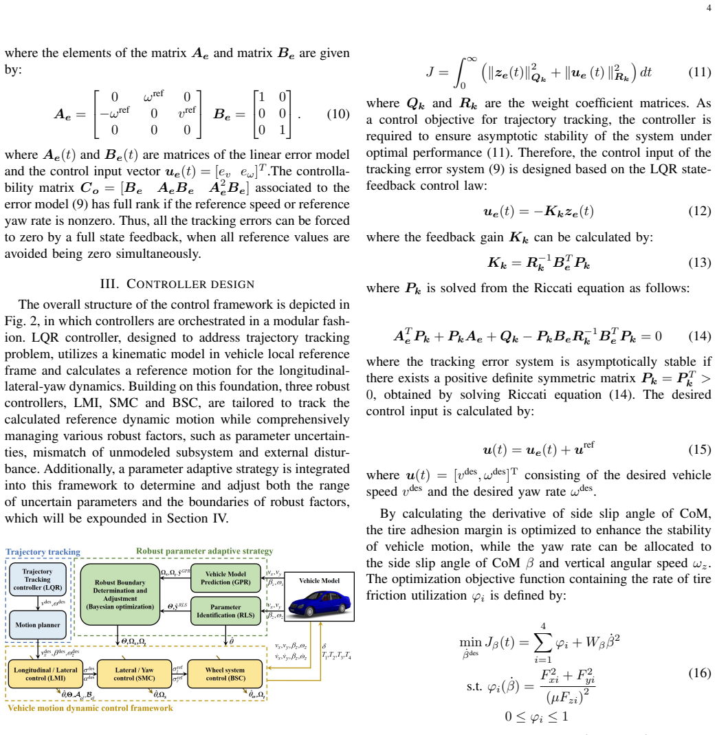
The central mechanism is the modular decomposition plus the parameter-adaptive boundary estimation loop. A linear-quadratic regulator uses the kinematic tracking-error model to output desired speed, side-slip angle, and yaw rate; three robust controllers (LMI, SMC, BSC) then track these references while handling parameter uncertainty, unmodeled subsystem mismatch, and external disturbances. The loop is closed by recursive least squares identifying tire stiffness, Gaussian process regression learning the residual dynamics to set the envelopes, and Bayesian optimization scaling the robust factor bounds via a global cost function. The LMI design's polytopic uncertainty model [ΔA ΔB] = M F(t)[Na Nb] with F(t)^T F(t) ≤ 1 is the load-bearing object for the stability proofs.
What would settle it
Run the same double-lane-change scenario with tire cornering stiffness reduced by more than the identified range (for example, a 40 percent drop or a change in road friction from μ ≈ 1 to μ ≈ 0.3) and measure lateral tracking error and sideslip envelope. If ARC's maximum error exceeds the claimed 0.043 m margin or the sideslip grows beyond the phase-plane attraction domain, the boundary-estimation loop has not captured the true uncertainty.
Extended reading notes
Core claim
The central claim is that a parameter-adaptive robust control framework (ARC), which decomposes the driving task into an LQR trajectory-tracking layer and three stacked robust motion-control layers (LMI for longitudinal-lateral dynamics, sliding-mode for lateral-yaw stability, backstepping for wheel dynamics), simultaneously improves tracking accuracy and yaw stability relative to standalone robust controllers. The improvement is attributed to the adaptive determination of robust boundaries: RLS tracks time-varying tire stiffness, GPR learns the magnitude of unmodeled subsystem mismatch and external disturbances, and Bayesian optimization scales those boundaries (1.50, 1.22, 0.51 in the experiments) to balance conservatism against robustness. The paper reports simulation evidence that ARC keeps the maximum lateral tracking error at 0.043 m and yields smaller, smoother sideslip and yaw-rate trajectories than the two baselines.
Load-bearing premise
All real uncertainties, model mismatches, and disturbances stay inside the estimated ranges: the tire parameters stay in the polytope Θ, the mismatch fits the bounded form [ΔA ΔB] = M F(t)[Na Nb] with F(t)^T F(t) ≤ 1, and the disturbance envelopes are correctly captured by the GPR-learned bounds.
Editorial extensions
If this is right
- Under the paper's assumptions, the same framework should transfer to other reference paths and speeds with no controller redesign, because the robust boundaries adapt online rather than being fixed worst-case constants.
- The guaranteed asymptotic stability of the LMI/SMC/BSC layers means the composite system's stability does not rely on the LQR tuning, so the tracking layer can be retuned independently.
- The Bayesian scaling coefficients indicate when the fixed-boundary design is conservative: for parameter uncertainty and internal disturbance the optimal scaling is greater than 1 (boundaries need enlarging), while for external disturbance it is less than 1 (boundaries can shrink).
- A practical consequence is that vehicle controllers can maintain tracking accuracy under emergency obstacle avoidance without increasing online optimization complexity relative to a single MPC.
Reading between the lines
- Both baseline controllers likely use fixed, conservatively large robust bounds; if their bounds were optimally tuned for this scenario, the reported gap in tracking error might shrink, so the claimed advantage is specifically about adaptive rather than fixed boundary selection.
- The modular split means the same adaptive boundary loop could be attached to other motion-control methods, such as NMPC or LPV/H-infinity, potentially improving them without changing their inner structure.
- Because the GPR boundary learner is trained on Carsim data, its performance on roads with different friction surfaces or tire wear would test whether the learned envelopes generalize or require periodic retraining.
- A testable extension is to run a sine-with-dwell or moose-test maneuver at higher speed to see whether the yaw-stability benefit persists near the handling limits.
Editorial analysis
A structured set of objections, weighed in public.
Referee Report
Summary. This paper proposes a modular trajectory tracking and motion control framework for autonomous vehicles. A kinematic LQR generates reference speed, sideslip angle, and yaw rate; three robust controllers (LMI, SMC, and back-stepping) track those references while addressing parameter uncertainty, unmodeled subsystem mismatch, and external disturbances. RLS is used for online tire-stiffness identification, GPR for estimating disturbance/model-mismatch bounds, and Bayesian optimization to tune robust-boundary scaling coefficients. Stability is claimed via Lyapunov arguments for each robust controller. The method is evaluated in a MATLAB/Simulink–Carsim joint simulation on a double-lane-change scenario at 60 km/h with injected 1000 N lateral-force and 1000 N·m yaw disturbances, reporting a maximum tracking error of 0.043 m for the proposed ARC framework versus 0.113 m for MPC and 0.104 m for an LMI controller.
Significance. If the framework performs as claimed, it offers a useful modular architecture: separating trajectory tracking from motion control while integrating three robust controllers with online parameter and boundary adaptation. The Lyapunov stability arguments are standard and self-contained, and the pseudocode in Algorithm 1 and Algorithm 2 is sufficiently concrete to reproduce the proposed adaptive strategy. The main empirical claim, however, is currently weakened by the in-sample tuning of the robust-boundary scaling coefficients on what appears to be the same scenario used for the final comparison, as well as by an apparent error in the tire side-slip angle model that feeds the LMI controller. The significance is therefore conditional on addressing these points.
major comments (3)
- [Section IV-C, Algorithm 2, Fig. 3, and Section V] The robust-boundary scaling coefficients αb=[1.50, 1.22, 0.51] are optimized by Bayesian optimization to minimize JG (Eq. 53), which includes tracking error, and the text says the optimized values are 'adopted to simulation in section V' (Fig. 3). Since Section V uses the same double-lane-change scenario with the same injected 1000 N / 1000 N·m disturbances, the reported comparison (0.043 m vs 0.113 m and 0.104 m maximum tracking error) is an in-sample tuning comparison, not an out-of-sample validation. The Lyapunov proofs guarantee stability for any feasible bounds, but they do not establish superiority over MPC/LMI; that claim rests entirely on this comparative simulation. Please validate on a scenario distinct from the tuning scenario, or provide cross-validation, sensitivity analysis, or multiple repeated trials with different disturbance realizations.
- [Section II-B, Eq. (4)] The tire side-slip angle definitions appear to have the ratio inverted and the sign of the steering term wrong: the paper gives α_fj = (v_x' + a ω_z')/v_y' − δ and α_rj = (v_x' − b ω_z')/v_y', whereas the standard definitions are α_f = δ − (v_y + a ω_z)/v_x and α_r = (b ω_z − v_y)/v_x. Since the LMI controller later outputs a desired side-slip angle α_des and the steering command is computed from it (Section III-B), this inconsistency affects the controller model itself, not just notation. Please correct or clarify the formula and re-check whether the subsequent LMI derivation and the Carsim implementation use consistent kinematic definitions.
- [Section IV-B and Section V] The GPR model is trained on data 'sourced from the Carsim simulation software' (Section IV-B), and the robust boundaries are then scaled using closed-loop simulations of the same Carsim model in Algorithm 2. This blurs the distinction between an 'unmodeled subsystem' and a mismatch that the GPR has effectively memorized from the validation plant. Consequently, the claimed robustness to unmodeled dynamics is not independently tested. Please use a validation plant or maneuver that is not part of the GPR training and boundary-optimization procedure, or state this limitation explicitly and temper the corresponding robustness claims.
minor comments (5)
- [Section I-B] The sentence 'Nam et al [30] introduces...' is associated with reference [30] (Cordeiro et al.), but the cited methodology on lateral tire force sensors and cornering stiffness estimation appears in reference [29] (Nam et al.). Please correct the citation.
- [Throughout] There are numerous typographical and stylistic errors, including 'duo to', 'designes', inconsistent spacing in 'A Vs', and inconsistent use of v_x', v_y' vs. v_x, v_y. A careful proofreading pass is needed.
- [Section III-D, Eq. (44)] The Lyapunov derivative is shown to satisfy ˙V_ω(e_ω) ≤ 0, and the text concludes asymptotic stability. Since Γ(e_ω) ≥ ϱ(e_ω)+Γ_0, strict negativity for e_ω ≠ 0 requires Γ_0 > 0 (or an additional argument if Γ_0 = 0). Please state this condition explicitly.
- [Section IV-C, Eq. (55)] The UCB acquisition function is written as arg min(μ_b + κ_b σ_b), whereas standard UCB maximizes μ + κσ. If the convention is to minimize the objective after a sign change, the sign of the exploration term should be clarified to avoid ambiguity.
- [Figures 7–9] The phase-plane figures lack axis labels and units, and the captions refer to subplots (a)–(c) whose layout is not fully clear from the text. Please add labels and explain what the dots and trajectories represent in each subplot.
Circularity Check
Performance comparison is partly a fit: Bayesian optimization tunes robust-boundary scaling on a simulation cost that includes tracking error, and the optimized coefficients are then used directly in the Section V double-lane-change comparison.
-
fitted input called prediction
[Section IV-C (Algorithm 2, Eq. 53) and Section V (Fig. 5)]
"J i G = PN k=1 (∥ze∥2 We + ∥av∥2 Wa + ∥φv∥2 Wφ); ... Carry out simulation experiment and record data ... Through algorithm 2, the robust scaling coefficients have been determined ... as 1.50, 1.22 and 0.51 respectively, which will be adopted to simulation in section V ... A double lane change scenario ... extreme values of 1000 N and 1000 N.m ... maximum tracking error of ARC (0.043m) significantly surpasses that of the other controllers (0.113m and 0.104m, respectively)."
Algorithm 2 selects αb=[αbθ, αbi, αbe] by minimizing JG, whose first term is the tracking-error norm ∥ze∥²_We. The optimized values are then explicitly 'adopted to simulation in section V,' where the same double-lane-change environment with 1000 N and 1000 N·m disturbances is used to report ARC's 0.043 m maximum tracking error against MPC and LMI. The manuscript does not state that the simulation experiments inside CalculateGlobalCost used a scenario distinct from the Section V comparison. Consequently, the headline accuracy figure is obtained after optimizing the very metric on which ARC is compared with the baselines, so the claimed improvement is partly a training-score fit rather than an independent out-of-sample prediction.
full rationale
The control-theoretic derivation is largely self-contained. The LMI stabilizing condition (Eqs. 26-29), the SMC Lyapunov argument (Eqs. 35-37), and the BSC Lyapunov argument (Eqs. 42-44) are proven analytically in the paper and do not rest on the simulation results or on self-citations. Citations to the authors' prior work ([25], [31]) appear as background and comparative context, not as load-bearing justifications for the stability theorems. The circularity is confined to the empirical performance claim: αb is tuned by Bayesian optimization against a cost functional that includes the same tracking-error measure used to declare ARC superior, and the tuned values are directly adopted in the Section V comparison. Because the text does not document a separate tuning scenario, the 0.043 m versus 0.113/0.104 m error comparison is vulnerable to being a training-score comparison rather than a validated prediction. This partial circularity lowers the score but does not invalidate the analytical stability contributions.
Assumptions & free parameters
free parameters (5)
- Robust scaling coefficients αbθ, αbi, αbe =
1.50, 1.22, 0.51
- GPR hyperparameters (l, σf^2, σε^2) =
not reported
- RLS forgetting factor parameters (λmin, h, σε) =
not reported
- LQR and robust controller weights (Qk, Rk, Q, R, ξ, kω) =
not reported
- Bayesian optimization UCB coefficient κb =
not reported
assumptions (6)
- standard math Lyapunov stability theorems and Schur complement for LMI conversion
- domain assumption Boundedness of parameter uncertainty and disturbances within compact sets Θ, Ωs, Ωt
- domain assumption Polytopic uncertainty representation [ΔA ΔB] = M F(t)[Na Nb] with F^T F <= 1
- domain assumption k(xs) > 0 for the sliding mode system
- domain assumption GPR provides a statistically valid estimate of model mismatch and disturbances
- standard math Reference speed or yaw rate nonzero for controllability
Cite this review
Pith. "Pith review of A Parameter Adaptive Trajectory Tracking and Motion Control Framework for Autonomous Vehicle." pith.science (2026). https://pith.science/paper/Y4C5RUXN
@misc{pith2026241117745,
  author       = {Pith},
  title        = {Pith review of: A Parameter Adaptive Trajectory Tracking and Motion Control Framework for Autonomous Vehicle},
  year         = {2026},
  howpublished = {\url{https://pith.science/paper/Y4C5RUXN}},
  note         = {Machine review of arXiv:2411.17745}
}
read the original abstract
This paper studies the trajectory tracking and motion control problems for autonomous vehicles (AVs). A parameter adaptive control framework for AVs is proposed to enhance tracking accuracy and yaw stability. While establishing linear quadratic regulator (LQR) and three robust controllers, the control framework addresses trajectory tracking and motion control in a modular fashion, without introducing complexity into each controller. The robust performance has been guaranteed in three robust controllers by considering the parameter uncertainties, mismatch of unmodeled subsystem as well as external disturbance, comprehensively. Also, the dynamic characteristics of uncertain parameters are identified by Recursive Least Squares (RLS) algorithm, while the boundaries of three robust factors are determined through combining Gaussian Process Regression (GPR) and Bayesian optimization machine learning methods, reducing the conservatism of the controller. Sufficient conditions for closed-loop stability under the diverse robust factors are provided by the Lyapunov method analytically. The simulation results on MATLAB/Simulink and Carsim joint platform demonstrate that the proposed methodology considerably improves tracking accuracy, driving stability, and robust performance, guaranteeing the feasibility and capability of driving in extreme scenarios.
Figures


Figures from the paper (5 more)


Reference graph
Works this paper leans on
-
[1]
F.-Y . Wang, “Drive like a machine: Remembering the origin and goal of autonomous driving and intelligent vehicles,” IEEE Trans. Intell. Veh. , vol. 8, no. 7, pp. 3763–3766, 2023
work page 2023
-
[2]
Autonomous vehicles: Autodriver algorithm and vehicle dynamics,
H. Marzbani, H. Khayyam, D. V . Quoc, and R. N. Jazar, “Autonomous vehicles: Autodriver algorithm and vehicle dynamics,” IEEE Trans. Veh. Technol., vol. 68, no. 4, pp. 3201–3211, 2019
work page 2019
-
[3]
H. Li, G. Yu, B. Zhou, P. Chen, Y . Liao, and D. Li, “Semantic-level maneuver sampling and trajectory planning for on-road autonomous driving in dynamic scenarios,” IEEE Trans. Veh. Technol., vol. 70, no. 2, pp. 1122–1134, 2021
work page 2021
-
[4]
Graph-based scenario- adaptive lane-changing trajectory planning for autonomous driving,
Q. Dong, Z. Yan, K. Nakano, X. Ji, and Y . Liu, “Graph-based scenario- adaptive lane-changing trajectory planning for autonomous driving,” IEEE Robotics and Automation Letters , vol. 8, no. 9, pp. 5688–5695, 2023
work page 2023
-
[5]
Y . Liu, X. Ji, K. Yang, X. He, X. Na, and Y . Liu, “Finite-time optimized robust control with adaptive state estimation algorithm for autonomous heavy vehicle,” Mech. Syst. Signal Proc. , vol. 139, p. 106616, 2020
work page 2020
-
[6]
G. Cai, L. Xu, Y . Liu, J. Feng, J. Liang, Y . Lu, and G. Yin, “Robust preview path tracking control of autonomous vehicles under time- varying system delays and saturation,” IEEE Trans. Veh. Technol., 2023
work page 2023
-
[7]
X. Cao, T. Xu, Y . Tian, and X. Ji, “Gain-scheduling lpv synthesis H ∞ robust lateral motion control for path following of autonomous vehicle via coordination of steering and braking,” Veh. Syst. Dyn., vol. 61, no. 4, pp. 968–991, 2023
work page 2023
-
[8]
Z. Qi, Q. Shi, and H. Zhang, “Tuning of digital pid controllers using particle swarm optimization algorithm for a can-based dc motor subject to stochastic delays,” IEEE Trans. Ind. Electron. , vol. 67, no. 7, pp. 5637–5646, 2019
work page 2019
Show all 34 references
-
[9]
Nested pid steering control for lane keeping in autonomous vehicles,
R. Marino, S. Scalzi, and M. Netto, “Nested pid steering control for lane keeping in autonomous vehicles,” Control Eng. Practice , vol. 19, no. 12, pp. 1459–1467, 2011
2011
-
[10]
Road-curvature-range-dependent path following controller design for autonomous ground vehicles subject to stochastic delays,
Q. Shi and H. Zhang, “Road-curvature-range-dependent path following controller design for autonomous ground vehicles subject to stochastic delays,” IEEE Trans. Intell. Transp. Syst. , vol. 23, no. 10, pp. 17 440– 17 450, 2022
2022
-
[11]
Output constraint control on path following of four-wheel independently actuated autonomous ground vehicles,
C. Hu, R. Wang, F. Yan, and N. Chen, “Output constraint control on path following of four-wheel independently actuated autonomous ground vehicles,” IEEE Trans. Veh. Technol. , vol. 65, no. 6, pp. 4033–4043, 2015
2015
-
[12]
Dynamic drifting control for general path tracking of autonomous vehicles,
G. Chen, X. Zhao, Z. Gao, and M. Hua, “Dynamic drifting control for general path tracking of autonomous vehicles,” IEEE Trans. Intell. Veh., 2023
2023
-
[13]
Design, analysis, and experiments of preview path tracking control for autonomous vehicles,
S. Xu and H. Peng, “Design, analysis, and experiments of preview path tracking control for autonomous vehicles,” IEEE Trans. Intell. Transp. Syst., vol. 21, no. 1, pp. 48–58, 2019
2019
-
[14]
Mpc-based cooperative control strategy of path planning and trajectory tracking for intelligent vehicles,
Z. Zuo, X. Yang, Z. Li, Y . Wang, Q. Han, L. Wang, and X. Luo, “Mpc-based cooperative control strategy of path planning and trajectory tracking for intelligent vehicles,” IEEE Transactions on Intelligent Vehicles, vol. 6, no. 3, pp. 513–522, 2021
2021
-
[15]
Mpc-based path tracking with pid speed control for high-speed autonomous vehicles considering time-optimal travel,
S.-p. Chen, G.-m. Xiong, H.-y. Chen, and D. Negrut, “Mpc-based path tracking with pid speed control for high-speed autonomous vehicles considering time-optimal travel,” J. Cent. South Univ. , vol. 27, no. 12, pp. 3702–3720, 2020
2020
-
[16]
Path-tracking and lateral stabil- isation for autonomous vehicles by using the steering angle envelope,
Q. Cui, R. Ding, C. Wei, and B. Zhou, “Path-tracking and lateral stabil- isation for autonomous vehicles by using the steering angle envelope,” Veh. Syst. Dyn., vol. 59, no. 11, pp. 1672–1696, 2021
2021
-
[17]
Real-time control for at-limit handling driving on a predefined path,
T. Novi, A. Liniger, R. Capitani, and C. Annicchiarico, “Real-time control for at-limit handling driving on a predefined path,” Veh. Syst. Dyn., 2019
2019
-
[18]
Nmpc-based path tracking control strategy for autonomous vehicles with stable limit handling,
T. Fu, H. Zhou, and Z. Liu, “Nmpc-based path tracking control strategy for autonomous vehicles with stable limit handling,” IEEE Trans. Veh. Technol., vol. 71, no. 12, pp. 12 499–12 510, 2022
2022
-
[19]
An adaptive hierarchical trajectory following control approach of autonomous four-wheel independent drive electric vehicles,
J. Guo, Y . Luo, and K. Li, “An adaptive hierarchical trajectory following control approach of autonomous four-wheel independent drive electric vehicles,” IEEE Trans. Intell. Transp. Syst. , vol. 19, no. 8, pp. 2482– 2492, 2017
2017
-
[20]
Holistic adaptive multi- model predictive control for the path following of 4wid autonomous vehicles,
Y . Liang, Y . Li, A. Khajepour, and L. Zheng, “Holistic adaptive multi- model predictive control for the path following of 4wid autonomous vehicles,” IEEE Trans. Veh. Technol., vol. 70, no. 1, pp. 69–81, 2020
2020
-
[21]
A gain-scheduled robust controller for autonomous vehicles path tracking based on lpv system with mpc and H∞,
Y . Tian, Q. Yao, P. Hang, and S. Wang, “A gain-scheduled robust controller for autonomous vehicles path tracking based on lpv system with mpc and H∞,” IEEE Trans. Veh. Technol., vol. 71, no. 9, pp. 9350– 9362, 2022
2022
-
[22]
Lpv static output feedback for constrained direct tilt control of narrow tilting vehicles,
A.-T. Nguyen, P. Chevrel, and F. Claveau, “Lpv static output feedback for constrained direct tilt control of narrow tilting vehicles,” IEEE Trans. Control Syst. Technol., vol. 28, no. 2, pp. 661–670, 2018
2018
-
[23]
Path tracking and direct yaw moment coordinated control based on robust mpc with the finite time horizon for autonomous independent-drive vehicles,
H. Peng, W. Wang, Q. An, C. Xiang, and L. Li, “Path tracking and direct yaw moment coordinated control based on robust mpc with the finite time horizon for autonomous independent-drive vehicles,” IEEE Transactions on Vehicular Technology , vol. 69, no. 6, pp. 6053–6066, 2020
2020
-
[24]
Model-predictive-control-based path tracking controller of autonomous vehicle considering parametric uncertainties and velocity-varying,
S. Cheng, L. Li, X. Chen, J. Wu et al., “Model-predictive-control-based path tracking controller of autonomous vehicle considering parametric uncertainties and velocity-varying,” IEEE Trans. Ind. Electron., vol. 68, no. 9, pp. 8698–8707, 2020
2020
-
[25]
Isolating trajectory tracking from motion control: A model predictive control and robust control framework for unmanned ground vehicles,
J. Song, G. Tao, Z. Zang, H. Dong, B. Wang, and J. Gong, “Isolating trajectory tracking from motion control: A model predictive control and robust control framework for unmanned ground vehicles,” IEEE Robot. Autom. Lett., vol. 8, no. 3, pp. 1699–1706, 2023
2023
-
[26]
Gain-scheduled steering and braking coordinated control in path tracking of intelligent heavy vehicles,
Q. Dong, X. Ji, Y . Liu, and Y . Liu, “Gain-scheduled steering and braking coordinated control in path tracking of intelligent heavy vehicles,” J. Dyn. Syst. Meas. Contr. , vol. 144, no. 10, p. 101006, 2022
2022
-
[27]
A novel approach for vehicle inertial parameter identification using a dual kalman filter,
S. Hong, C. Lee, F. Borrelli, and J. K. Hedrick, “A novel approach for vehicle inertial parameter identification using a dual kalman filter,” IEEE Transactions on Intelligent Transportation Systems , vol. 16, pp. 151–161, 2015
2015
-
[28]
A switching rollover controller coupled with closed-loop adaptive vehicle parameter identification,
M. Akar and A. D. Dere, “A switching rollover controller coupled with closed-loop adaptive vehicle parameter identification,” IEEE Transac- tions on Intelligent Transportation Systems , vol. 15, pp. 1579–1585, 2014
2014
-
[29]
Lateral stability control of in-wheel- motor-driven electric vehicles based on sideslip angle estimation using lateral tire force sensors,
K. Nam, H. Fujimoto, and Y . Hori, “Lateral stability control of in-wheel- motor-driven electric vehicles based on sideslip angle estimation using lateral tire force sensors,” IEEE Transactions on Vehicular Technology, vol. 61, no. 5, pp. 1972–1985, 2012
1972
-
[30]
Estimation of vertical, lateral, and longitudinal tire forces in four-wheel vehicles using a delayed interconnected cascade-observer structure,
R. A. Cordeiro, A. C. Victorino, J. R. Azinheira, P. A. V . Ferreira, E. C. de Paiva, and S. S. Bueno, “Estimation of vertical, lateral, and longitudinal tire forces in four-wheel vehicles using a delayed interconnected cascade-observer structure,”IEEE/ASME Transactions on Mec...
2019
-
[31]
Gain-scheduled LPV/H ∞ strategy for steering and braking coordination of intelligent commercial vehicle lateral automation,
Y . Sun, J. Song, H. He, T. Xu, and X. Ji, “Gain-scheduled LPV/H ∞ strategy for steering and braking coordination of intelligent commercial vehicle lateral automation,” IEEE Trans. Intell. Veh., 2024
2024
-
[32]
A tutorial on gaussian process regression: Modelling, exploring, and exploiting functions,
E. Schulz, M. Speekenbrink, and A. Krause, “A tutorial on gaussian process regression: Modelling, exploring, and exploiting functions,” J. Math. Psychol., vol. 85, pp. 1–16, 2018. Jiarui Song received the B.S. degree a from the Beijing Institute of Technology, Beijing, China, in
2018
-
[2019]
degree in mechanical engineering from School of Vehicle and Mobility, Tsinghua University, Beijing, China
She is currently working towards the Ph.D. degree in mechanical engineering from School of Vehicle and Mobility, Tsinghua University, Beijing, China. Her research interests include a dynamic control, autonomous driving, and intelligent transportation systems. Xuewu Ji (Member,...
1987
-
[2020]
degree in mechanical engineering with the Beijing Institute of Technology, Beijing, China, in 2023
He received the M.S. degree in mechanical engineering with the Beijing Institute of Technology, Beijing, China, in 2023. He is currently working towards the Ph.D. degree in mechanical engineering from School of Vehicle and Mobility, Tsinghua University, Beijing, China. His res...
2023
Reviewed August 12, 2026 · model on record in the stance chip above.
Discussion (0). Continue with ORCID to comment.