REVIEW 3 major objections 6 minor 1 cited by
Midplane based 3D single pass unbiased segment-to-segment contact interaction using penalty method
T0 review · 3 major / 6 minor · reviewed 2026-08-07 · deepseek-v4-flash
Pith's one-line read Contact tractions between finite-element surfaces can be computed in a single pass with no master or slave labels, by penalising interpenetration measured through a midplane.
desk verdict The midplane single-pass idea is a real extension and the patch test result is worth seeing, but Algorithm 1 as printed skips exactly the penetrating points, so the paper's own recipe cannot produce the reported contact forces. read the letter →
The pith
A machine-rendered reading of the paper's core claim, the machinery that carries it, and where it could break.
The reading
What carries the argument
The machinery is the per-pair midplane together with the intersection polygon of full facet projections. The midplane normal is $\mathbf{n}_{\mathrm{mp}}=(\mathbf{n}_1-\mathbf{n}_2)/\|\mathbf{n}_1-\mathbf{n}_2\|$, where $\mathbf{n}_1,\mathbf{n}_2$ are the outward unit normals of the two facets' representative planes, so the contact direction is symmetric by construction. The paper's key geometric observation is that projecting a bilinear quadrilateral onto a plane preserves its bilinear parametric structure, so one inverse bilinear mapping (supplied as an analytic algorithm) locates the physical point on each facet corresponding to any quadrature point on the midplane. The overlap polygon is triangulated from its centroid and integrated with symmetric triangle quadrature; the same penalty traction is then applied with opposite sign to the two facets, making force and moment equilibrium a property of the discretisation rather than a post-processing correction.
What would settle it
Construct two warped bilinear facets whose projections onto a common midplane overlap while no physical point of either facet lies inside the other body, then compare the method's integrated contact force with the force obtained by numerically integrating the actual overlap volume; if the projected-intersection force is nonzero, the contact region does not represent true interpenetration.
Extended reading notes
Core claim
The central claim is that single-pass contact can be unbiased if the contact interface is defined geometrically rather than through a master-slave ordering. For each facet pair, the authors construct a representative plane per facet, take a midplane equi-inclined to both, project both bilinear facets orthogonally onto that midplane, and use the intersection polygon of the projections as the contact region. The gap is measured at integration points by shooting along the midplane normal to both physical facets; the penalty traction $\mathbf{t}_N=-\epsilon_N g_N H(-g_N)\,\mathbf{n}_{\mathrm{mp}}$ is integrated over the triangulated intersection polygon and distributed to the nodes of both facets through their shape functions. In the benchmarks the uniform patch-test pressure is reproduced to 10–11 digits, and the method converges to the analytical Hertz, flat-punch, and bar-collision solutions with mesh refinement and suitably high penalty. The authors conclude that no second pass is needed to remove biasing, and that the formulation is equally valid for self-contact because it never privileges one side of the interface.
Load-bearing premise
The load-bearing premise is that the intersection of the two full orthogonal projections onto the midplane is the true three-dimensional interpenetration region; the paper chooses full projections so that off-midplane overlap is included, but it does not prove equality for warped or curved facets.
Editorial extensions
If this is right
- A single pass replaces the dual-pass strategy for unbiased contact, so the contact work scales with the number of interacting pairs instead of twice that number.
- Nonmatching and nonconformal meshes transmit uniform pressure across flat interfaces, which is the condition the classical node-to-segment method fails.
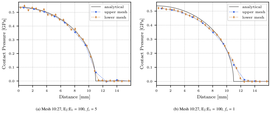
- For curved Hertzian contact and flat-punch indentation, the pressure profile approaches the analytical solution as the mesh is refined or the penalty factor is raised.
- Self-contact of a single body is detected and constrained with the same code path as contact between two bodies, because no surface is assigned a privileged role.
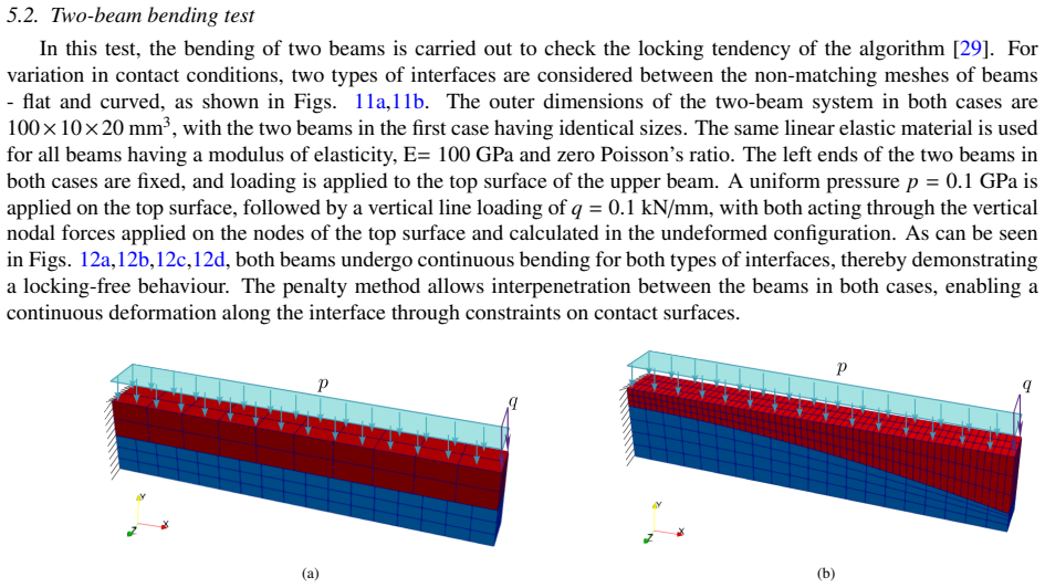
- Two-beam bending shows no locking and smooth load transfer across both flat and curved contact interfaces.
Reading between the lines
- Because the nodal forces are integrated from a common traction, the method should conserve linear and angular momentum across nonconformal interfaces by construction; the oblique-cylinder example is consistent with this, though a formal proof is not given.
- The same midplane construction suggests a natural tangential and friction extension: a tangential traction law could be integrated over the same intersection polygon without reintroducing master-slave bias; the paper lists friction as future work.
- The projection-intersection step is essentially 2D polygon clipping, so the per-pair cost is low; coupling the method with hierarchical spatial search could scale it to very large explicit-dynamics models.
- For higher-order or warped elements the property that projection preserves bilinear parametric structure may fail; generalising the method would require a new inverse-mapping or quadrature strategy.
Editorial analysis
A structured set of objections, weighed in public.
Referee Report
Summary. The paper proposes a single-pass, midplane-based segment-to-segment penalty contact formulation for explicit finite element analysis of 3D deformable solids. For each potentially contacting pair of bilinear facets, the authors construct a local midplane, project both facets onto it, intersect the projected polygons, triangulate the intersection, and integrate a penalty traction derived from the normal gap at quadrature points. The resulting nodal forces are applied symmetrically to both facets without master-slave labeling. The method is validated on a contact patch test, two-beam bending, Hertzian contact, a rigid flat punch indentation, self-contact, elastic and inelastic bar collisions, and oblique cylinder collision.
Significance. If correct, the method would provide an unbiased, single-pass segment-to-segment contact scheme at roughly half the computational cost of dual-pass approaches while passing the contact patch test and maintaining force-moment equilibrium by construction. The paper gives a detailed geometric taxonomy of facet configurations, a concrete algorithm, and a broad set of benchmark problems, which are useful contributions. The main strengths are the clear single-pass formulation and the demonstration of symmetric traction transfer in several demanding configurations. However, the paper does not ship machine-checked proofs or reproducible code, and, as explained below, the published algorithm contains a sign error that reverses the penetration test, so the reported results cannot be reproduced from the printed procedure.
major comments (3)
- [Algorithm 1, lines 12–15; Eqs. (11)–(13), (26)] The interpenetration test in Algorithm 1 is inverted relative to the mathematical formulation. The paper defines interpenetration as g_N = g_N · n_mp < 0, and Eq. (26) makes the traction proportional to H(-g_N), so contact forces should be computed only when g_N < 0. Algorithm 1, however, says 'if g_N < 0 then continue to the next quadrature point as there is no interpenetration' and performs the force update only in the else branch. As printed, every genuinely penetrating quadrature point is skipped and non-penetrating points contribute through H(-g_N) with zero traction, so the algorithm cannot produce the contact forces reported in Section 5. This is a load-bearing defect: either the condition in Algorithm 1 must be reversed (skip g_N >= 0 and update for g_N < 0), or the results were generated by an undocumented variant of the algorithm. Please correct the algorithm and confirm at least the patch test and Hertz results with the corrected condition.
- [Section 3.2.2, Figure 7, Eq. (31)] The paper selects the intersection of the full orthogonal projections of both facets onto the midplane as the integration region, arguing that this captures 'true interpenetration' including parts P and S that do not cross the midplane. No proof is given that, for warped or curved bilinear facets, the intersection of full projections equals the projection of the actual 3D overlap volume. The integration in Eq. (31) is performed over this polygon, so any mismatch between the projected intersection and the true overlap directly changes the integrated traction and undermines the accuracy claims. Please provide a proof for general bilinear facets or add a numerical study comparing the projected-region integral with the exact interpenetration volume for nontrivial warped configurations.
- [Section 3.3, footnote; Sections 5.1–5.7] The penalty parameter is defined as epsilon_N = f_s times the minimum bulk modulus, and the footnote admits that this choice 'does not preserve unit consistency' and is 'treated as a tunable parameter.' The validation then uses different f_s values in different tests (f_s = 100 in the patch test, f_s = 10 in Hertz, f_s = 40 in the punch test, f_s = 1–5 in dynamic problems), so the statement that the method 'converges towards the analytical solution with mesh refinement and a suitably high penalty factor' is not supported by a predictive selection rule. This is not fatal for a penalty method, but the central accuracy claim should be qualified by this tunability, and ideally a single penalty choice or a dimensionally consistent penalty should be demonstrated across benchmarks.
minor comments (6)
- [Eqs. (19)–(21)] Equation (20) writes the projection of the second facet as γ1,mp_hA, which should be γ2,mp_hB, and Eq. (21) then uses γ1,mp_hB on the right-hand side; the second projected polygon should be that of facet B.
- [Eq. (26)] The expression for t_N contains a stray dγ inside the definition; it should read t_N = -epsilon_N g_N H(-g_N · n_mp) n_mp, with dγ reserved for the integrals in Eqs. (30)–(31).
- [Eq. (32)] The shorthand [ΨqVencl]_i is introduced only after use and is not defined; the reader must infer that it denotes the quadrature sum on the left-hand side.
- [Figure 19 and Figure B.25] The legend entries for the penalty scaling factors render as '= .', '= .', and '= .' in the extracted text, so the figure cannot be read without the original fonts; the f_s values should be explicitly printed.
- [Section 3.3 and Section 5] The quadrature rule is fixed at 13 points per triangle in all tests, but no convergence study with respect to the number of quadrature points is reported; since the traction integral involves possibly non-smooth gaps, a brief quadrature convergence check would strengthen the accuracy claims.
- [References and reproducibility] The implementation is described as part of the in-house solver DEST with only a documentation URL [49]; providing a version identifier, a more detailed algorithm listing, or sample input files would materially improve reproducibility.
Circularity Check
No significant circularity; the proposed contact derivation is self-contained. A separate internal sign inconsistency in Algorithm 1 is flagged as a correctness/reproducibility issue, not as circularity.
full rationale
The central derivation does not reduce to its own inputs. The contact traction is defined through the interpenetration gap in Eqs. (11)-(14) and (22)-(26), with the Heaviside factor H(-g_N) making the traction respond to true interpenetration; the penalty factor is introduced as a material-based, tunable constant, and the benchmarks (patch test, Hertz, punch, bar impact) are external analytical or classical targets, not quantities fitted to define the method. The geometric choice in Sec. 3.2.2 to use full projections rather than only midplane-penetrating portions is an internal modeling assumption whose accuracy can be questioned, but it is not circular because it is not defined in terms of the analytical solutions it is later compared against. The self-citations, [46] for inverse bilinear mapping and [49] for the in-house solver DEST, are implementation utilities rather than load-bearing evidence for the scientific claim; no uniqueness theorem from prior author work is invoked to forbid alternatives, and no known empirical result is merely renamed. I note, separately, that Algorithm 1 steps 12-15 ('if g_N < 0 then continue to the next quadrature point as there is no interpenetration') contradict Eq. (26), where traction is nonzero precisely when g_N < 0; as printed, the algorithm would skip every penetrating quadrature point. This is an internal consistency/reproducibility defect, not a circular-derivation defect, and it does not affect the circularity score but should be corrected in the manuscript.
Assumptions & free parameters
free parameters (6)
- Penalty scaling factor fs =
1, 5, 10, 40, 100 depending on test
- Penalty factor epsilon_N =
min(bulk modulus) * fs
- Number of quadrature points per triangle =
13
- Contact detection angle threshold =
80 degrees
- Artificial bulk viscosity coefficients =
0.6 linear, 1.5 quadratic
- Bounding box expansion width =
unspecified
assumptions (6)
- standard math Balance of linear momentum and standard weak form for deformable solids
- domain assumption Frictionless contact with Karush-Kuhn-Tucker conditions
- ad hoc to paper Representative facet plane normal from averaged cross products is equidistant from all nodes
- ad hoc to paper Intersection of full orthogonal projections of facets onto the midplane captures the true interpenetration region
- ad hoc to paper Penalty parameter derived from bulk modulus is a valid contact stiffness despite dimensional inconsistency
- domain assumption Bilinear parametric lines remain bilinear after orthogonal projection onto a plane
Cite this review
Pith. "Pith review of Midplane based 3D single pass unbiased segment-to-segment contact interaction using penalty method." pith.science (2026). https://pith.science/paper/HPVNYH3K
@misc{pith2026250604841,
  author       = {Pith},
  title        = {Pith review of: Midplane based 3D single pass unbiased segment-to-segment contact interaction using penalty method},
  year         = {2026},
  howpublished = {\url{https://pith.science/paper/HPVNYH3K}},
  note         = {Machine review of arXiv:2506.04841}
}
read the original abstract
This work introduces a contact interaction methodology for an unbiased treatment of contacting surfaces without assigning surfaces as master and slave. The contact tractions between interacting discrete segments are evaluated with respect to a midplane in a single pass, inherently maintaining the equilibrium of tractions. These tractions are based on the penalisation of true interpenetration between opposite surfaces, and the procedure of their integral for discrete contacting segments is described in this paper. A meticulous examination of the different possible geometric configurations of interacting 3D segments is presented to develop visual understanding and better traction evaluation accuracy. The accuracy and robustness of the proposed method are validated against the analytical solutions of the contact patch test, two-beam bending, Hertzian contact, and flat punch test, thus proving the capability to reproduce contact between flat surfaces, curved surfaces, and sharp corners in contact, respectively. The method passes the contact patch test with the uniform transmission of contact pressure matching the accuracy levels of finite elements. It converges towards the analytical solution with mesh refinement and a suitably high penalty factor. The effectiveness of the proposed algorithm also extends to self-contact problems and has been tested for self-contact between flat and curved surfaces with inelastic material. Dynamic problems of elastic and inelastic collisions between bars, as well as oblique collisions of cylinders, are also presented. The ability of the algorithm to resolve contacts between flat and curved surfaces for nonconformal meshes with high accuracy demonstrates its versatility in general contact problems.
Figures


Figures from the paper (21 more)






Forward citations
Cited by 1 Pith paper
-
Unbiased higher-order frictional contact using midplane and patch based segment-to-segment penalty method
A single-pass, unbiased, segment-to-segment penalty contact method is extended from linear to quadratic hexahedral elements by subdividing curved faces into bilinear subfacets and enforcing contact through a corrected...
Reference graph
Works this paper leans on
-
[1]
K. L. Johnson, Contact Mechanics, Cambridge University Press
-
[2]
A. Munjiza, D. Owen, N. Bicanic, A combined finite-discrete element method in transient dynamics of fracturing solids 12 (2) 145–174. doi:10.1108/02644409510799532
-
[3]
W. K. Liu, S. Li, H. S. Park, Eighty Years of the Finite Element Method: Birth, Evolution, and Futuredoi:10.1007/s11831-022-09740-9
-
[4]
Bathe, KJ Bathe – Finite Element Procedures, 2nd Edition, Prentice-Hall
K.-J. Bathe, KJ Bathe – Finite Element Procedures, 2nd Edition, Prentice-Hall
-
[5]
T. A. Laursen, Computational Contact and Impact Mechanics, Springer Berlin Heidelberg. doi:10.1007/978-3-662-04864-1
-
[6]
Wriggers, Computational Contact Mechanics, J
P. Wriggers, Computational Contact Mechanics, J. Wiley & Sons
-
[7]
T. J. R. Hughes, R. L. Taylor, J. L. Sackman, A. Curnier, W. Kanoknukulchai, A finite element method for a class of contact-impact problems 8 (3) 249–276. doi:10.1016/0045-7825(76)90018-9
-
[8]
Kim, Introduction to Nonlinear Finite Element Analysis, Springer US
N.-H. Kim, Introduction to Nonlinear Finite Element Analysis, Springer US. doi:10.1007/978-1-4419-1746-1
Show all 68 references
-
[9]
S. Jin, D. Sohn, J. H. Lim, S. Im, A node-to-node scheme with the aid of variable-node elements for elasto-plastic contact analysis 102 (12) 1761–1783. doi:10.1002/nme.4862
-
[10]
S. Jin, D. Sohn, S. Im, Node-to-node scheme for three-dimensional contact mechanics using polyhedral type variable-node elements 304 217–242. doi:10.1016/j.cma.2016.02.019
2016 doi
-
[11]
W. Xing, C. Song, F. Tin-Loi, A scaled boundary finite element based node-to-node scheme for 2D frictional contact problems 333 114–146. doi:10.1016/j.cma.2018.01.012
2018 doi
-
[12]
W. Xing, J. Zhang, C. Song, F. Tin-Loi, A node-to-node scheme for three-dimensional contact problems using the scaled boundary finite element method 347 928–956. doi:10.1016/j.cma.2019.01.015
2019 doi
-
[13]
T. J. Hughes, R. L. Taylor, W. Kanoknukulchai, A finite element method for large displacement contact and impact problems 468–495
-
[14]
J. O. Hallquist, NIKE2D: An implicit, finite-deformation, finite-element code for analyzing the static and dynamic response of two- dimensional solids
-
[15]
J. O. Hallquist, G. L. Goudreau, D. J. Benson, Sliding interfaces with contact-impact in large-scale Lagrangian computations 51 (1) 107–137. doi:10.1016/0045-7825(85)90030-1
-
[16]
D. P. Flanagan, T. Belytschko, A uniform strain hexahedron and quadrilateral with orthogonal hourglass control 17 (5) 679–706. doi: 10.1002/nme.1620170504
-
[17]
R. L. Taylor, P. Papadopoulos, On a patch test for contact problems in two dimensions 690 702. URL https://csml.berkeley.edu/Preprints/textr91b.pdf
-
[18]
Zavarise, L
G. Zavarise, L. De Lorenzis, A modified node-to-segment algorithm passing the contact patch test 79 (4) 379–416.doi:10.1002/nme.2559
-
[19]
Zavarise, L
G. Zavarise, L. De Lorenzis, The node-to-segment algorithm for 2D frictionless contact: Classical formulation and special cases 198 (41) 3428–3451. doi:10.1016/j.cma.2009.06.022
2009 doi
-
[20]
C. Sun, G. R. Liu, S. H. Huo, G. Wang, C. Yu, Z. Li, A novel node-to-segment algorithm in smoothed finite element method for contact problemsdoi:10.1007/s00466-023-02327-6
-
[21]
Kang, S.-M
S.-H. Kang, S.-M. Lee, S. Shin, Improved area regularization technique for penalty-method-based node-to-segment contact analysis 71 (4) 801–825. doi:10.1007/s00466-023-02269-z
-
[22]
M. Puso, J. Solberg, A dual pass mortar approach for unbiased constraints and self-contact 367 113092. doi:10.1016/j.cma.2020. 113092
2020 doi
-
[23]
D. M. Neto, M. C. Oliveira, L. F. Menezes, Surface Smoothing Procedures in Computational Contact Mechanics 24 (1) 37–87. doi: 10.1007/s11831-015-9159-7
-
[24]
K. T. Danielson, Curved node-to-face contact schemes for higher-order finite elements in lumped-mass explicit methods 395 115056. doi: 10.1016/j.cma.2022.115056
2022
-
[25]
V . A. Yastrebov, Numerical Methods in Contact Mechanics, Numerical Methods in Engineering Series, ISTE ; Wiley
-
[26]
J. C. Simo, P. Wriggers, R. L. Taylor, A perturbed Lagrangian formulation for the finite element solution of contact problems 50 (2) 163–180. doi:10.1016/0045-7825(85)90088-X
-
[27]
Zavarise, P
G. Zavarise, P. Wriggers, A segment-to-segment contact strategy 28 (4-8) 497–515. doi:10.1016/S0895-7177(98)00138-1
-
[28]
El-Abbasi, K.-J
N. El-Abbasi, K.-J. Bathe, Stability and patch test performance of contact discretizations and a new solution algorithm 79 (16) 1473–1486. doi:10.1016/S0045-7949(01)00048-7
-
[29]
M. A. Puso, T. A. Laursen, A mortar segment-to-segment contact method for large deformation solid mechanics 193 (6) 601–629. doi: 10.1016/j.cma.2003.10.010
2003 doi
-
[30]
L. D. Lorenzis, P. Wriggers, T. J. R. Hughes, Isogeometric contact: A review 37 (1) 85–123. doi:10.1002/gamm.201410005
-
[31]
Bernardi, N
C. Bernardi, N. Debit, Y . Maday, Coupling finite element and spectral methods: First results 54 (189) 21–39. doi:10.1090/ S0025-5718-1990-0995205-7
1990
-
[32]
M. A. Puso, A 3D mortar method for solid mechanics 59 (3) 315–336. doi:10.1002/nme.865
-
[33]
A. Popp, M. Gitterle, M. W. Gee, W. A. Wall, A dual mortar approach for 3D finite deformation contact with consistent linearization 83 (11) 1428–1465. doi:10.1002/nme.2866
-
[34]
R. P. Carvalho, A. M. C. Carneiro, F. M. A. Pires, A. Popp, An e fficient algorithm for rigid/deformable contact interaction based on the dual mortar methoddoi:10.1007/s00466-022-02226-2
-
[35]
Farah, A
P. Farah, A. Popp, W. A. Wall, Segment-based vs. element-based integration for mortar methods in computational contact mechanics 55 (1) 209–228. doi:10.1007/s00466-014-1093-2
-
[36]
T. A. Laursen, J. C. Simo, A continuum-based finite element formulation for the implicit solution of multibody, large deformation-frictional contact problems 36 (20) 3451–3485. doi:10.1002/nme.1620362005
-
[37]
T. W. McDevitt, T. A. Laursen, A mortar-finite element formulation for frictional contact problems 48 (10) 1525–1547. doi:10.1002/ 1097-0207(20000810)48:10<1525::AID-NME953>3.0.CO;2-Y . 31
-
[38]
M. A. Puso, T. A. Laursen, J. Solberg, A segment-to-segment mortar contact method for quadratic elements and large deformations 197 (6) 555–566. doi:10.1016/j.cma.2007.08.009
2007 doi
-
[39]
O. C. Zienkiewicz, R. L. Taylor, J. Z. Zhu, The Finite Element Method: Its Basis and Fundamentals, seventh edition Edition, Elsevier, Butterworth-Heinemann
-
[40]
Zavarise, P
G. Zavarise, P. Wriggers, E. Stein, B. A. Schrefler, Real contact mechanisms and finite element formulation—a coupled thermomechanical approach 35 (4) 767–785. doi:10.1002/nme.1620350409
-
[41]
Papadopoulos, R
P. Papadopoulos, R. Taylor, A simple algorithm for three-dimensional finite element analysis of contact problems 46 (6) 1107–1118. doi: 10.1016/0045-7949(93)90096-V
-
[42]
Belytschko, M
T. Belytschko, M. O. Neal, Contact-impact by the pinball algorithm with penalty and Lagrangian methods 31 (3) 547–572. doi:10.1002/ nme.1620310309
-
[43]
Batistic, P
I. Batistic, P. Cardi ff, Z. Tukovi, A finite volume penalty based segment-to-segment method for frictional contact problems 101 673–693. doi:10.1016/j.apm.2021.09.009
2021 doi
-
[44]
G. R. Cowper, Gaussian quadrature formulas for triangles 7 (3) 405–408. doi:10.1002/nme.1620070316
-
[45]
D. A. Dunavant, High degree e fficient symmetrical Gaussian quadrature rules for the triangle 21 (6) 1129–1148. doi:10.1002/nme. 1620210612
-
[46]
Sahu, Bilinear-Inverse-Mapper: Analytical Solution and Algorithm for Inverse Mapping of Bilinear Interpolation of Quadrilaterals
I. Sahu, Bilinear-Inverse-Mapper: Analytical Solution and Algorithm for Inverse Mapping of Bilinear Interpolation of Quadrilaterals. doi: 10.2139/ssrn.4790071
-
[47]
Bonet, J
J. Bonet, J. Peraire, An alternating digital tree (ADT) algorithm for 3D geometric searching and intersection problems 31 (1) 1–17. doi: 10.1002/nme.1620310102
-
[48]
I. E. Sutherland, G. W. Hodgman, Reentrant polygon clipping 17 (1) 32–42. doi:10.1145/360767.360802
-
[49]
Bronik, I
K. Bronik, I. Sahu, N. Petrinic, u. family =al, prefix=et, DEST documentation. URL https://dest-doc.readthedocs.io/en/latest/
-
[50]
Belytschko, T
T. Belytschko, T. J. Hughes, P. Burgers, Computational methods for transient analysis
-
[51]
J. P. Ahrens, B. Geveci, C. Law, ParaView: An end-user tool for large-data visualization, in: Visualization Handbook, Elsevier, pp. 717–731. doi:10.1016/B978-012387582-2/50038-1
-
[52]
Ayachit, The ParaView Guide: A Parallel Visualization Application, Kitware, Inc
U. Ayachit, The ParaView Guide: A Parallel Visualization Application, Kitware, Inc
-
[53]
S. L. Kwon, S. Kim, D. Ha, G. J. Yun, A fully nonlinear three-dimensional dynamic frictional contact analysis method under large deformation with the area regularizationdoi:10.1007/s00366-023-01795-x
-
[54]
Hertz, Ueber die Ber ¨uhrung fester elastischer K¨orper
H. Hertz, Ueber die Ber ¨uhrung fester elastischer K¨orper. 1882 (92) 156–171. doi:10.1515/crll.1882.92.156
-
[55]
K. L. Johnson, One Hundred Years of Hertz Contact 196 (1) 363–378. doi:10.1243/PIME_PROC_1982_196_039_02
-
[56]
V . L. Popov, M. Heß, E. Willert, Handbook of Contact Mechanics: Exact Solutions of Axisymmetric Contact Problems, Springer Berlin Heidelberg. doi:10.1007/978-3-662-58709-6
-
[57]
N. J. Carpenter, R. L. Taylor, M. G. Katona, Lagrange constraints for transient finite element surface contact 32 (1) 103–128.doi:10.1002/ nme.1620320107
-
[58]
K. T. Danielson, J. L. O’Daniel, Reliable second-order hexahedral elements for explicit methods in nonlinear solid dynamics 85 (9) 1073–
-
[59]
K. T. Danielson, M. D. Adley, T. N. Williams, Second-order finite elements for Hex-Dominant explicit methods in nonlinear solid dynamics 119 63–77. doi:10.1016/j.finel.2016.02.008
2016 doi
-
[60]
Browning, K
R. Browning, K. Danielson, M. Adley, Higher-order finite elements for lumped-mass explicit modeling of high-speed impacts 137 103458. doi:10.1016/j.ijimpeng.2019.103458
2019
-
[61]
R. S. Browning, K. T. Danielson, D. L. Littlefield, Second-order pyramid element formulations suitable for lumped-mass explicit methods in nonlinear solid mechanics 405 115854. doi:10.1016/j.cma.2022.115854
2022
-
[62]
M. Zang, W. Gao, Z. Lei, A contact algorithm for 3D discrete and finite element contact problems based on penalty function method 48 (5) 541–550. doi:10.1007/s00466-011-0606-5
-
[63]
P. Otto, L. De Lorenzis, J. F. Unger, Explicit dynamics in impact simulation using a NURBS contact interface 121 (6) 1248–1267. doi: 10.1002/nme.6264
-
[64]
O. C. Zienkiewicz, R. L. Taylor, D. Fox, The Finite Element Method for Solid and Structural Mechanics, 7th Edition, Elsevier /Butterworth- Heinemann
-
[65]
Belytschko, W
T. Belytschko, W. K. Liu, B. Moran, K. I. Elkhodary, Nonlinear Finite Elements for Continua and Structures, second edition Edition, Wiley
-
[66]
Duczek, H
S. Duczek, H. Gravenkamp, Mass lumping techniques in the spectral element method: On the equivalence of the row-sum, nodal quadrature, and diagonal scaling methods 353 516–569. doi:10.1016/j.cma.2019.05.016
2019 doi
-
[67]
Dunne, N
F. Dunne, N. Petrinic, Introduction to Computational Plasticity, Oxford University Press. 32
-
[1102]
doi:10.1002/nme.3003
Reviewed August 7, 2026 · model on record in the stance chip above.
Discussion (0). Sign in to comment.