REVIEW 3 major objections 6 minor 5 cited by
Cross-linked rotatable antenna arrays set every antenna's orientation with one shared row angle and one shared column angle, cutting motors from 2MN to M+N while closely matching fully flexible rotation performance.
Reviewed by Pith at T0; open to challenge. T0 means a machine referee read the full paper against a public rubric. the ladder, T0–T4 →
A cross-linked rotatable antenna array, whose row and column tracks set each antenna's orientation, nearly matches fully flexible per-antenna rotation in simulated multiuser uplinks with only M+N motors instead of 2MN.
T0 review reviewed 2026-08-03 challenge →
load-bearing objection A clean single-user ULA equivalence result inside an otherwise overclaimed multiuser architecture paper; the central 'close to flexible' claim is only tested in a far-field regime where it isn't sharp. the 3 major comments →
Wireless Communication with Cross-Linked Rotatable Antenna Array: Architecture Design and Rotation Optimization
The pith
A machine-rendered reading of the paper's core claim, the machinery that carries it, and where it could break.
The reading
Core claim
The central discovery is that rotational coupling need not be a performance killer. By mounting each antenna at the crossing of a shared horizontal and vertical track, the orientation of every antenna is governed by just two shared angles, α_m and β_n. The paper proves that for a 1×N uniform linear array in a single-user line-of-sight channel, these shared angles can still point every antenna exactly at the user, giving the same SNR as fully flexible rotation while using N+1 motors instead of 2N. For multi-user planar arrays, the paper's alternating optimization over MMSE beamforming and feasible-direction rotation updates shows, in simulation, that a good row-column partition lets the coupl
What carries the argument
The key object is the cross-linked rotation structure: an M×N array whose antennas sit at intersections of horizontal and vertical tracks, with one motor per row and one per column. The rotation of antenna (m,n) is the product R(α_m,β_n)=R_{α_m}R_{β_n}, so the pointing vector is f=R(α_m,β_n)[1,0,0]^T. This single identity makes the orientation of all MN antennas a function of only M+N angles. Proposition 2 is the load-bearing theoretical result: for a 1×N array it gives explicit α_m and β_n that align every antenna with the user, proving exact equivalence to fully flexible rotation. For panel-level rotation, the same coupling plus physical non-reflection and CPU-blockage constraints (Proposi
Load-bearing premise
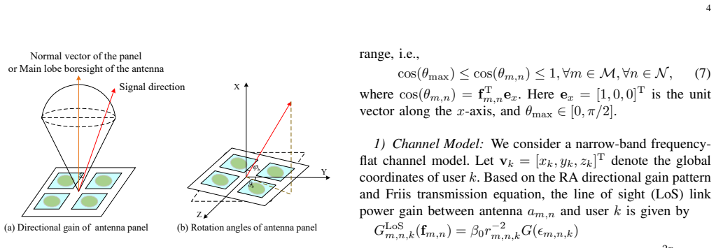
The central premise is that the antenna gain really is G(ε)=G0 cos^{2p}(ε) for ε≤π/2 and zero otherwise, and that the dual-axis gimbal in Fig. 1 realizes exactly the product rotation R(α_m,β_n)=R_{α_m}R_{β_n}; since no prototype or measured pattern is reported, all 128%/25%/84% gains rest on this model.
What would settle it
Build an 8×8 CL-RA prototype with the proposed dual-axis gimbal, measure the directional gain pattern and single-user SNR against the cos^{2p} prediction of Eq. (38), and compare multi-user sum rates with the simulated 128%/25% gains; if the measured pattern differs or the gimbal couples the row and column axes, the equivalence in Proposition 2 and the simulated gains are not realized.
If this is right
- Motor count falls from 2MN to M+N for an M×N element-level array, and further to (M+N)/√Q_b when antennas are grouped into rotatable panels.
- For a single-user 1×N uniform linear array, the CL-RA design is exactly as good as fully flexible orientation, with closed-form row and column angles that align every antenna with the user.
- In the multi-user simulation setup, element-level CL rotation beats panel-level CL rotation by 25% and fixed-direction antennas by 128%; a row-column partition of 2×32 nearly matches the flexible-orientation baseline.
- Panel-level rotation has a smaller feasible angle set due to mutual-reflection and CPU-blockage constraints; a 2×1 panel partition still beats array-wise rotation by 17%, while finer partitions such as 2×2 can be worse.
- With discrete angle sets of 15 levels per axis, a genetic algorithm recovers an 84% gain over fixed orientation, beating naive nearest-projection rounding by 15%.
Where Pith is reading between the lines
- The exact ULA result suggests a general design heuristic the paper does not state: coupling is harmless when each row contains a single element, so the best CL partition is one that keeps row width small while preserving enough column diversity; this could be tested by sweeping 2×32, 4×16, and 8×8 partitions.
- The performance numbers assume an ideal gimbal. A natural robustness check is to add small random coupling between α_m and β_n and re-run the alternating-optimization algorithm; if the 128% gain persists, the architecture is mechanically forgiving.
- Since the paper invokes uplink-downlink duality, its MMSE/feasible-direction machinery should transfer to downlink sum-rate maximization with power allocation; that extension is not simulated in the paper.
- The panel feasible-range analysis implies a partition-design rule: for a given array footprint there is an optimal panel count that balances rotational degrees of freedom against physical constraints; a quantitative version could be formulated as an outer optimization over partition geometry.
Editorial analysis
A structured set of objections, weighed in public.
Referee Report
Summary. The paper proposes a cross-linked rotatable antenna (CL-RA) array in which M horizontal and N vertical tracks drive row- and column-level rotations, reducing the number of motors from 2MN to M+N (or to (M+N)/sqrt(Q) for panel grouping). It models an uplink multiuser system with distance- and orientation-dependent LoS/NLoS channels, formulates a sum-rate maximization over receive beamforming and coupled rotation angles, derives an exact single-user ULA equivalence (Prop. 2), and proposes alternating optimization with MMSE beamforming and a feasible-direction rotation update, plus a genetic algorithm for discrete rotations. Simulations claim that the CL-RA element-level scheme nearly matches the flexible orientation benchmark, exceeds panel-level rotation by 25%, and outperforms fixed orientation by 128%.
Significance. The architecture is a sensible and timely cost-reduction concept for rotatable-antenna systems. Proposition 2 and its proof in Appendix B are clean, first-principles results and constitute a genuine strength: for a 1xN ULA, the cross-linked structure can exactly match fully flexible orientation with N+1 motors. The paper contains no fitted parameters; the reported percentages are direct outputs of the stated channel and antenna-gain model. If the multiuser rotation update is corrected and the simulation regime is expanded to cases where per-antenna orientation diversity actually matters, the paper would provide a useful performance/complexity characterization of a new RA architecture. At present, however, the central 'quite close to flexible' claim rests on an approximation error in the algorithm derivation and on a simulation geometry that does not stress the row/column coupling.
major comments (3)
- [§IV-A2, Eq. (51)] The update identity R(u^{(t)}_{m,n}) = R(u^{(t-1)}_{m,n}) R(Δu_{m,n}) is not correct for the parameterization R(u)=R_α R_β. In fact R_{α+Δα} R_{β+Δβ} = R_α R_{Δα} R_β R_{Δβ}, whereas R_α R_β R_{Δα} R_{Δβ} is different; equality would require [R_{Δα}, R_β]=0, which is false for rotations about distinct axes. Consequently, the small-angle linearization in Eq. (53) is not the first-order variation of f_{m,n} with respect to (α_m, β_n), and the linear program (56) and constraint (54) are not valid tangent-plane approximations. The monotonicity/convergence argument in §IV-C therefore does not follow. Please replace this with an exact parameter-space gradient (e.g., finite differences of the true R(α+δα, β+δβ)) or prove that the approximation preserves feasibility and ascent up to a controlled error.
- [§VI, Table I and Figs. 6–7] The central claim that CL-RA is 'quite close' to flexible orientation is tested only in a quasi-far-field geometry. With an 8×8 array at Δ=λ/2 (aperture ≈0.34 m) and users at 50–70 m, the direction from different array elements to a user varies by at most ≈0.4°. For the cos^{2p} pattern with p=2 this yields negligible per-element orientation loss, so an array-wise orientation is nearly optimal and the comparison cannot discriminate between M+N and 2MN orientation DoFs. Proposition 2 is only for a ULA; no analytical bound or near-field/large-aperture simulation is provided for UPA. Please add a test where per-antenna orientation diversity matters (near-field, larger aperture, or strongly angle-dependent channel) or derive a scaling law for the loss caused by the row/column coupling. Otherwise the abstract's 'quite close to flexible' is an overgeneralization of a regime-specific observatio
- [§VI-C, Fig. 7] The partition comparison in Fig. 7 does not hold the number of motors fixed: the 2×32 partition uses M+N=34 motors, the 4×16 partition uses 20, and the 8×8 partition uses 16. The observation that 2×32 performs best may simply reflect its larger number of orientation DoFs rather than any property of row-column coupling. To support the conclusion about 'carefully designing the row-column partition,' the comparison should be normalized by motor count or accompanied by a complexity-penalized metric. This issue is secondary to the main claim but should be addressed in a revision.
minor comments (6)
- [Section V heading] The heading reads 'DISCRETE ROTATION ANGELS' — should be 'ANGLES'.
- [Throughout] Several typos: 'Armio' should be 'Armijo' (Algorithm 1), 'folowing' (Section II-B), 'th number' (Section II-C), and 'scatters' in Table I should be 'scatterers'.
- [Fig. 5] The abbreviation 'wo' is used in the legend but not defined in the caption; clarify that it means 'without' physical constraints.
- [Eq. (6)] The directional gain is defined for ε∈(0, π/2), but the boresight value at ε=0 is needed for the aligned case. Use [0,π/2) or explicitly define G(0)=G0.
- [Section II-A] Reference [43] (cross-linked movable antenna array) is closely related to the proposed architecture and should be discussed in the architecture section to clearly delineate novelty relative to that prior work.
- [Section V] The genetic algorithm is heuristic; this is acceptable, but the lack of any optimality or convergence guarantee for the discrete problem should be stated explicitly rather than implied by the continuous-algorithm convergence discussion.
Circularity Check
No significant circularity: the ULA equivalence is a constructive derivation and the simulation gains are model outputs, not fitted quantities.
full rationale
The paper's claimed derivation chain is self-contained rather than circular. Proposition 2, the only analytical equivalence result, is a constructive geometric proof: for the 1×N ULA case it exhibits explicit row and column angles (Eqs. 41–42) from the pointing condition f(u_m,n)=u_0 (Eq. 70), showing that the shared row angle α_1 plus per-column angles β_n can point every antenna at the user. This is a genuine first-principles derivation, not an assumption equivalent to the conclusion. The multi-user sum-rate results (25%, 128%, 84%, etc.) are outputs of the stated optimization problems under the stated channel and gain models; no parameter is fitted to reproduce these percentages, and the flexible baseline is the same model with fewer constraints. The only self-referential element is adoption of the directional gain model G(ε)=G0 cos^{2p}(ε) from prior rotatable-antenna work, some co-authored by the present authors, but that is an explicit modeling assumption used as an input, not a load-bearing 'prediction' or a uniqueness argument forced by self-citation. Any concern about validity in far-field-like simulation geometry is a correctness/generalization issue, not circularity.
Axiom & Free-Parameter Ledger
free parameters (3)
- Directivity factor p =
2 (Table I; varied in Fig. 8)
- Maximum zenith rotation angle θ_max =
π/6 default; π/12 used for the 128% headline
- Row-column partition of the array =
4×16 or 2×32 recommended in Fig. 7
axioms (5)
- domain assumption Directional gain pattern G(ε)=G0 cos^{2p}(ε) for ε∈(0,π/2), 0 otherwise, with G0=2(2p+1) (Eq. 6)
- domain assumption LoS channel gain follows Friis β0 r^{-2} times directional gain, with phase e^{-j2π r/λ} (Eqs. 8-9)
- domain assumption Bi-static scattering model with D clusters, RCS σ_d, and random phase χ_d (Eq. 11)
- ad hoc to paper Mechanical constraints (20c) and panel inequality constraints (32c),(32d) fully characterize physical feasibility and mutual-coupling avoidance
- ad hoc to paper Rotation matrices compose as R(u_{m,n})=R_{α_m}R_{β_n} and the cross-linked track/gimbal mechanism realizes independent α_m, β_n without mechanical coupling or backlash (Eq. 3, Fig. 1)
invented entities (1)
-
Cross-linked rotatable antenna (CL-RA) array with dual-axis gimbal and cardan shaft
no independent evidence
Cite this review
Pith. "Pith review of Wireless Communication with Cross-Linked Rotatable Antenna Array: Architecture Design and Rotation Optimization." pith.science (2026). https://pith.science/paper/H46RUE4X
@misc{pith2026260104862,
  author       = {Pith},
  title        = {Pith review of: Wireless Communication with Cross-Linked Rotatable Antenna Array: Architecture Design and Rotation Optimization},
  year         = {2026},
  howpublished = {\url{https://pith.science/paper/H46RUE4X}},
  note         = {Machine review of arXiv:2601.04862}
}
read the original abstract
Rotatable antenna (RA) technology can harness additional spatial degrees of freedom by enabling the dynamic three-dimensional orientation control of each antenna. Unfortunately, the hardware cost and control complexity of traditional RA systems is proportional to the number of RAs. To address the issue, we consider a cross-linked (CL) RA structure, which enables the coordinated rotation of multiple antennas, thereby offering a cost-effective solution. To evaluate the performance of the CL-RA array, we investigate a CL-RA-aided uplink system. Specifically, we first establish system models for both antenna element-level and antenna panel-level rotation. Then, we formulate a sum rate maximization problem by jointly optimizing the receive beamforming at the base station and the rotation angles. For the antenna element-level rotation, we derive the optimal solution of the CL-RA array under the single-user case. Subsequently, for two rotation schemes, we propose an alternating optimization algorithm to solve the formulated problem in the multi-user case, where the receive beamforming and the antenna rotation angles are obtained by applying the minimum mean square error method and feasible direction method, respectively. In addition, considering the hardware limitations, we apply the genetic algorithm to address the discrete rotation angles selection problem. Simulation results show that by carefully designing the row-column partition scheme, the performance of the CL-RA architecture is quite close to that of the flexible antenna orientation scheme. Moreover, the CL antenna element-level scheme surpasses the CL antenna panel-level scheme by 25% and delivers a 128% performance improvement over conventional fixed-direction antennas.
Figures




Forward citations
Cited by 5 Pith papers
-
Joint Transmit and Receive Antenna Orientation Design for Secure MIMO Communications
Jointly optimizing rotatable-antenna orientations with transmit beamforming and artificial-noise covariance in MIMO systems yields higher secrecy rates than fixed-orientation baselines.
-
Two-Timescale Design for Rotatable-Antenna Systems With Imperfect CSI: Rate Analysis and Orientation Optimization
Two-timescale rotatable-antenna design derives closed-form rates for MRC and wZF under imperfect CSI and optimizes orientations via projected gradient, showing different preferred rotations for estimation error versus rate.
-
Joint Transceiver Orientation Optimization for Rotatable-Antenna MIMO Capacity Maximization
Jointly optimizing rotatable antenna orientations and transmit covariance under spherical constraints significantly increases MIMO channel capacity over fixed-orientation baselines.
-
Joint Transceiver Orientation Optimization for Rotatable-Antenna MIMO Capacity Maximization
Jointly optimizing transmit covariance and per-antenna boresight directions under a zenith-angle cap gives substantial simulated capacity gains for rotatable-antenna MIMO.
-
Joint Transmit and Receive Antenna Orientation Design for Secure MIMO Communications
Jointly optimizing transmit/receive rotatable-antenna orientations with beamforming and artificial noise improves secrecy rate in MIMO wiretap channels, extending RA-secure designs to MIMO and multicast.
Reference graph
Works this paper leans on
-
[1]
On the road to 6G: Visions, requirements, key technologies, and testbeds,
C.-X. Wanget al., “On the road to 6G: Visions, requirements, key technologies, and testbeds,”IEEE Commun. Surveys Tut., vol. 25, no. 2, pp. 905–974, Feb. 2023
2023
-
[2]
Massive MIMO and mmWave for 5G wireless HetNet: Potential benefits and challenges,
T. E. Bogale and L. B. Le, “Massive MIMO and mmWave for 5G wireless HetNet: Potential benefits and challenges,”IEEE V eh. Tech. Mag., vol. 11, no. 1, pp. 64–75, Feb. 2016
2016
-
[3]
Scaling up MIMO: Opportunities and challenges with very large arrays,
F. Ruseket al., “Scaling up MIMO: Opportunities and challenges with very large arrays,”IEEE Signal Process. Mag., vol. 30, no. 1, pp. 40–60, Dec. 2012
2012
-
[4]
Movable antennas for wireless commu- nication: Opportunities and challenges,
L. Zhu, W. Ma, and R. Zhang, “Movable antennas for wireless commu- nication: Opportunities and challenges,”IEEE Commun. Mag., vol. 62, no. 6, pp. 114–120, Oct. 2023
2023
-
[5]
Modeling and performance analysis for movable antenna enabled wireless communications,
——, “Modeling and performance analysis for movable antenna enabled wireless communications,”IEEE Trans. Wireless Commun., vol. 23, no. 6, pp. 6234–6250, Nov. 2023
2023
-
[6]
Fluid antenna systems,
K.-K. Wong, A. Shojaeifard, K.-F. Tong, and Y . Zhang, “Fluid antenna systems,”IEEE Trans. Wireless Commun., vol. 20, no. 3, pp. 1950–1962, Nov. 2020
1950
-
[7]
Two-timescale design for mov- able antenna-enabled multiuser MIMO systems,
Z. Zheng, Q. Wu, W. Chen, and G. Hu, “Two-timescale design for mov- able antenna-enabled multiuser MIMO systems,”IEEE Trans. Commun., vol. 73, no. 11, pp. 10 554–10 571, Jul. 2025
2025
-
[8]
MIMO capacity characterization for movable antenna systems,
W. Ma, L. Zhu, and R. Zhang, “MIMO capacity characterization for movable antenna systems,”IEEE Trans. Wireless Commun., vol. 23, no. 4, pp. 3392–3407, Sept. 2023
2023
-
[9]
An information-theoretic characterization of MIMO-FAS: Optimization, diversity-multiplexing tradeoff and q-outage capacity,
W. K. New, K.-K. Wong, H. Xu, K.-F. Tong, and C.-B. Chae, “An information-theoretic characterization of MIMO-FAS: Optimization, diversity-multiplexing tradeoff and q-outage capacity,”IEEE Trans. Wireless Commun., vol. 23, no. 6, pp. 5541–5556, Oct. 2023
2023
-
[10]
Movable antenna enhanced networked integrated sensing and communication system,
Y . Guo, W. Chen, Q. Wu, Y . Liu, Q. Wu, K. Wang, J. Li, and L. Xu, “Movable antenna enhanced networked integrated sensing and communication system,”arXiv preprint arXiv: 2411.09426, 2024
arXiv 2024
-
[11]
Joint discrete antenna positioning and beamforming optimization in movable antenna enabled full-duplex ISAC networks,
Z. Li, J. Ba, Z. Su, H. Peng, Y . Wang, W. Chen, and Q. Wu, “Joint discrete antenna positioning and beamforming optimization in movable antenna enabled full-duplex ISAC networks,”IEEE Trans. Wireless Commun., early access, Jul. 2025
2025
-
[12]
H. Wang, Q. Wu, Y . Jiang, Z. Zheng, Z. Zhang, Y . Zhu, Y . Gao, W. Chen, G. Liu, and A. Jamalipour, “Reconfigurable airspace: Synergizing mov- able antenna and intelligent surface for low-altitude ISAC networks,” arXiv preprint arXiv: 2511.10310, 2024
arXiv 2024
-
[13]
Q. Wu, Z. Zheng, Y . Gao, W. Mei, X. Wei, W. Chen, and B. Ning, “Inte- grating movable antennas and intelligent reflecting surfaces (MA-IRS): Fundamentals, practical solutions, and opportunities,”arXiv preprint arXiv: 2506.14636, 2025
arXiv 2025
-
[14]
Movable intelligent surface (MIS) for wireless communications: Architecture, modeling, algorithm, and prototyping,
Z. Zheng, Q. Wu, W. Chen, X. Wu, and W. Zhu, “Movable intelligent surface (MIS) for wireless communications: Architecture, modeling, algorithm, and prototyping,”IEEE Trans. Wireless Commun., early access, Oct. 2025
2025
-
[15]
Integrat- ing movable antennas and intelligent reflecting surfaces for coverage enhancement,
Y . Gao, Q. Wu, W. Mei, G. Chen, W. Chen, and Z. Zheng, “Integrat- ing movable antennas and intelligent reflecting surfaces for coverage enhancement,”arXiv preprint arXiv: 2506.21375, 2025
arXiv 2025
-
[16]
Intelligent reflecting surfaces for wireless networks: Deployment architectures, key solutions, and field trials,
Q. Wu, G. Chen, Q. Peng, W. Chen, Y . Yuan, Z. Cheng, J. Dou, Z. Zhao, and P. Li, “Intelligent reflecting surfaces for wireless networks: Deployment architectures, key solutions, and field trials,”IEEE Wireless Communications, vol. 32, no. 6, pp. 141–148, May 2025
2025
-
[17]
UA V-enabled wireless networks with movable-antenna array: Flexible beamforming and trajectory design,
W. Liu, X. Zhang, H. Xing, J. Ren, Y . Shen, and S. Cui, “UA V-enabled wireless networks with movable-antenna array: Flexible beamforming and trajectory design,”IEEE Wireless Commun. Lett., vol. 14, no. 3, pp. 566–570, Aug. 2025
2025
-
[18]
Joint optimization of UA V height and antenna configuration for UA V-mounted movable antenna,
X.-W. Tang, Y . Shi, Y . Huang, and Q. Wu, “Joint optimization of UA V height and antenna configuration for UA V-mounted movable antenna,” IEEE Wireless Commun. Lett., early access, Oct. 2025
2025
-
[19]
UA V-mounted movable antenna: Joint optimization of UA V placement and antenna configuration,
X. Tang, Y . Shi, Y . Huang, and Q. Wu, “UA V-mounted movable antenna: Joint optimization of UA V placement and antenna configuration,”arXiv preprint arXiv: 2409.02469, 2025
arXiv 2025
-
[20]
Movable antenna aided NOMA: Joint antenna position- ing, precoding, and decoding design,
Z. Xiaoet al., “Movable antenna aided NOMA: Joint antenna position- ing, precoding, and decoding design,”arXiv preprint arXiv: 2412.12531, 2025
Pith/arXiv arXiv 2025
-
[21]
Movable antennas enabled wireless- powered NOMA: Continuous and discrete positioning designs,
Y . Gao, Q. Wu, and W. Chen, “Movable antennas enabled wireless- powered NOMA: Continuous and discrete positioning designs,”IEEE Trans. Wireless Commun., early access, Nov. 2025
2025
-
[22]
Movable antenna empowered downlink NOMA systems: Power allocation and antenna position optimization,
Y . Zhou, W. Chen, Q. Wu, X. Zhu, and N. Cheng, “Movable antenna empowered downlink NOMA systems: Power allocation and antenna position optimization,”IEEE Wireless Commun. Lett., vol. 13, no. 10, pp. 2772–2776, Aug. 2024
2024
-
[23]
6DMA enhanced wireless network with flexible antenna position and rotation: Opportunities and challenges,
X. Shao and R. Zhang, “6DMA enhanced wireless network with flexible antenna position and rotation: Opportunities and challenges,”IEEE Commun. Mag., vol. 63, no. 4, pp. 121–128, Mar. 2025
2025
-
[24]
6D movable antenna based on user distribution: Modeling and optimization,
X. Shao, Q. Jiang, and R. Zhang, “6D movable antenna based on user distribution: Modeling and optimization,”IEEE Trans. Wireless Commun., vol. 24, no. 1, pp. 355–370, Nov. 2024
2024
-
[25]
6D movable antenna enhanced wireless network via discrete position and rotation optimiza- tion,
X. Shao, R. Zhang, Q. Jiang, and R. Schober, “6D movable antenna enhanced wireless network via discrete position and rotation optimiza- tion,”IEEE J. Sel. Areas Commun., vol. 43, no. 3, pp. 674–687, Jan. 2025
2025
-
[26]
6-D movable antenna enhanced interference mitigation for cellular-connected UA V communications,
T. Ren, X. Zhang, L. Zhu, W. Ma, X. Gao, and R. Zhang, “6-D movable antenna enhanced interference mitigation for cellular-connected UA V communications,”IEEE Wireless Commun. Lett., vol. 14, no. 6, pp. 1618–1622, Mar. 2025
2025
-
[27]
Modeling and optimization for rotatable antenna enabled wireless communication,
Q. Wu, B. Zheng, T. Ma, and R. Zhang, “Modeling and optimization for rotatable antenna enabled wireless communication,” inProc. IEEE ICC, Montreal, QC, Canada, 2025, pp. 1055–1060
2025
-
[29]
Rotatable antenna enabled wireless communication: Modeling and optimization,
B. Zheng, Q. Wu, T. Ma, and R. Zhang, “Rotatable antenna enabled wireless communication: Modeling and optimization,”arXiv preprint arXiv: 2501.02595, 2025
arXiv 2025
-
[30]
Rotatable antenna enabled spectrum sharing: Joint antenna orientation and beam- forming design,
X. Peng, Q. Wu, Z. Zheng, W. Chen, Y . Zhu, and Y . Gao, “Rotatable antenna enabled spectrum sharing: Joint antenna orientation and beam- forming design,”arXiv preprint arXiv: 2509.19912, 2025
arXiv 2025
-
[31]
Rotatable antenna-enhanced cell-free communication,
K. Pan, B. Zheng, Y . Tan, E. Björnson, R. Schober, and R. Zhang, “Rotatable antenna-enhanced cell-free communication,”arXiv preprint arXiv: 2512.04742, 2025
Pith/arXiv arXiv 2025
-
[32]
Rotatable antenna array enabled UA V mmWave massive MIMO communication,
X. Zhanget al., “Rotatable antenna array enabled UA V mmWave massive MIMO communication,”IEEE Trans. Commun., early access, Oct. 2025
2025
-
[33]
Rotatable antenna-enabled secure wireless communication,
L. Dai, B. Zheng, Q. Wu, C. You, R. Schober, and R. Zhang, “Rotatable antenna-enabled secure wireless communication,”arXiv preprint arXiv: 2504.10473, 2025
Pith/arXiv arXiv 2025
-
[34]
Rotatable antennas for integrated sensing and communications,
C. Zhou, C. You, B. Zheng, X. Shao, and R. Zhang, “Rotatable antennas for integrated sensing and communications,”IEEE Wireless Commun. Lett., vol. 14, no. 9, pp. 2838–2842, Jun. 2025
2025
-
[35]
Low-altitude ISAC with rotatable active and passive arrays,
Z. Zheng, Q. Wu, Y . Zhu, H. Wang, Y . Gao, W. Chen, and J. Xiong, “Low-altitude ISAC with rotatable active and passive arrays,”arXiv preprint arXiv: 2512.20987, 2025
arXiv 2025
-
[36]
L. Dai, B. Zheng, Y . Tan, L. Zhu, F. Chen, and R. Zhang, “Rotatable antenna enabled wireless communication system with visual recognition: A prototype implementation,”arXiv preprint arXiv: 2502.17097, 2025
Pith/arXiv arXiv 2025
-
[37]
A demo of radar sensing aided rotatable antenna for wireless communication,
Q. Dai, B. Zheng, Q. Wang, X. Xiong, J. Tang, X. Shao, L. Zhu, and R. Zhang, “A demo of radar sensing aided rotatable antenna for wireless communication,” inProc. IEEE ECIE, Guangzhou, China, 2025, pp. 205–208
2025
-
[38]
A v-band micromachined 2-D beam-steering antenna driven by magnetic force with polymer-based hinges,
B. Chang-Wooket al., “A v-band micromachined 2-D beam-steering antenna driven by magnetic force with polymer-based hinges,”IEEE Trans. Microw. Theory Tech., vol. 51, no. 1, pp. 325–331, Jan. 2003
2003
-
[39]
Electronically steered metasurface antenna,
B. Michael, S. Timothy, F. I. Mohammadreza, and N. G. . D. R. S. Jonah, “Electronically steered metasurface antenna,”Sci Rep, vol. 11, no. 4693, Feb. 2021
2021
-
[40]
Rotatable antenna enabled wireless communication and sensing: Opportunities and challenges,
B. Zheng, T. Ma, C. You, J. Tang, R. Schober, and R. Zhang, “Rotatable antenna enabled wireless communication and sensing: Opportunities and challenges,”arXiv preprint arXiv: 2505.16828, 2025
Pith/arXiv arXiv 2025
-
[41]
Ro- tatable antenna-enabled spectrum sharing in cognitive radio systems,
Y . Tan, B. Zheng, Y . Fang, W. K. N. Derrick, J. Xu, and R. Zhang, “Ro- tatable antenna-enabled spectrum sharing in cognitive radio systems,” arXiv preprint arXiv: 2509.25656, 2025
arXiv 2025
-
[42]
Aerial 6D movable antenna-enabled cell-free networks,
W. Wang, Y . Huang, X. Shao, and C. Zhang, “Aerial 6D movable antenna-enabled cell-free networks,”IEEE Trans. V eh. Tech., early access, Sept. 2025
2025
-
[43]
L. Zhu, H. Sun, W. Ma, Z. Xiao, and R. Zhang, “Multiuser communi- cations aided by cross-linked movable antenna array: Architecture and optimization,”arXiv preprint arXiv: 2505.03175, 2025. 14
Pith/arXiv arXiv 2025
-
[44]
A matlab tool for solving linear goal programming problems,
T. Rocha, A. Borges, S. Paredes, and A. Pinho, “A matlab tool for solving linear goal programming problems,” inProc. 5th Exp. Int. Conf., Funchal, Portugal, Oct. 2019, pp. 337–342
2019
This paper was first reviewed by deepseek-v4-flash on August 3, 2026.
discussion (0)
Sign in with ORCID, Apple, or X to comment. Anyone can read and Pith papers without signing in.