Explicit Turn Resolution with Anisotropic Homogenisation for Efficient 3D Magneto-Thermal Finite-Element Simulation of Large-Scale No-Insulation HTS Magnets
Pith reviewed 2026-06-28 20:16 UTC · model grok-4.3
The pith
The EXTRA method mixes explicit turns near leads and defects with anisotropic homogenization to enable accurate 3D magneto-thermal simulations of large no-insulation HTS magnets.
A machine-rendered reading of the paper's core claim, the machinery that carries it, and where it could break.
Core claim
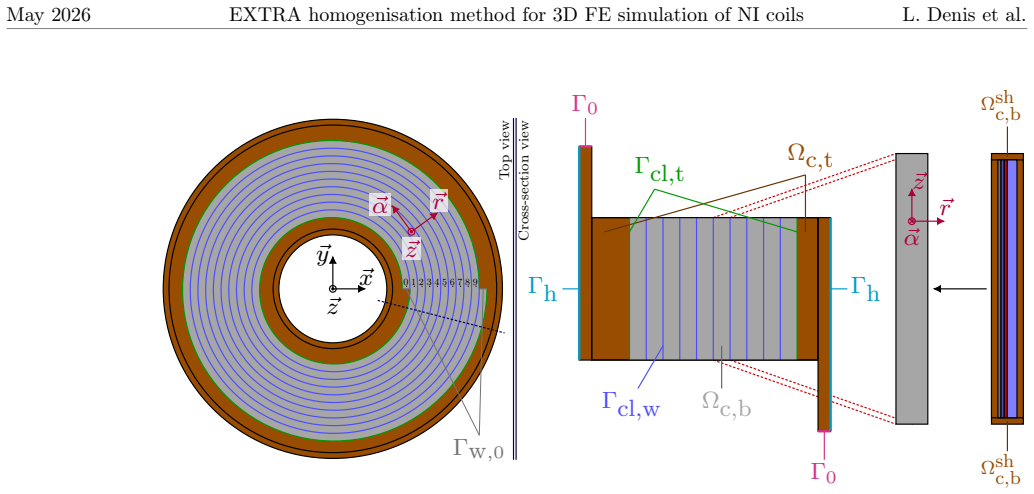
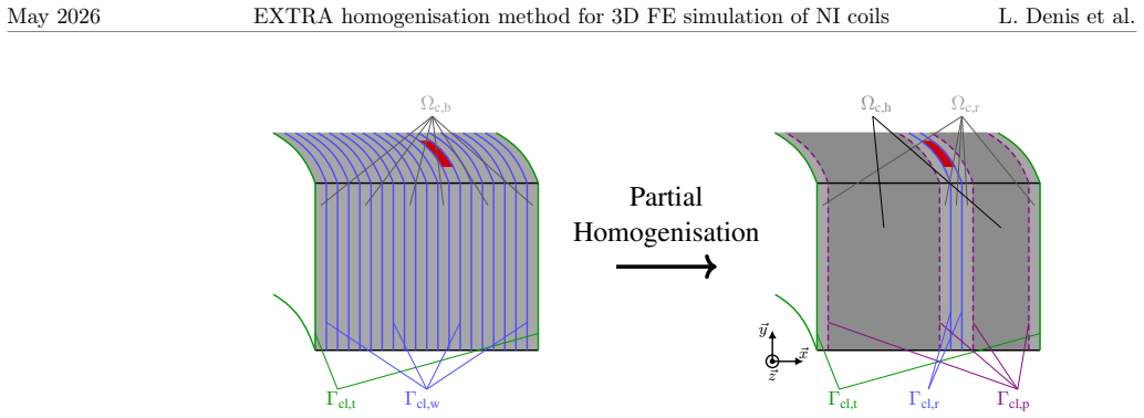
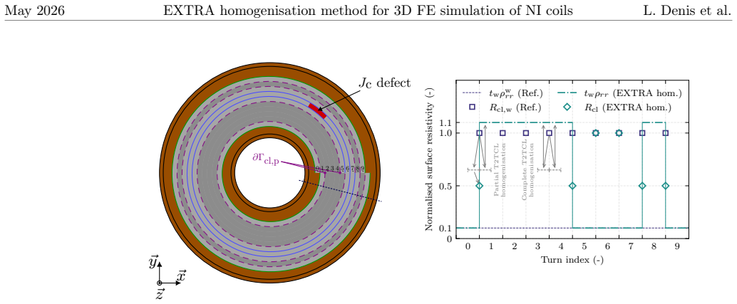
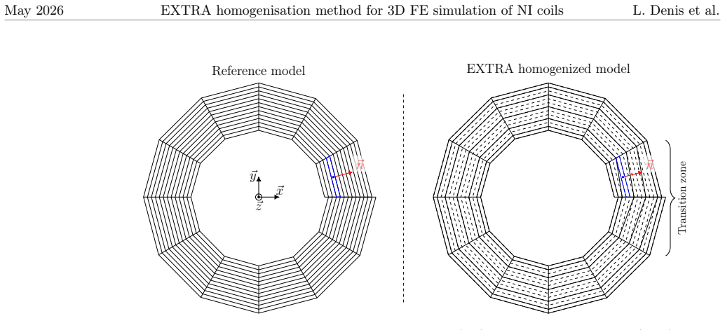
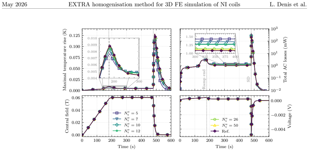
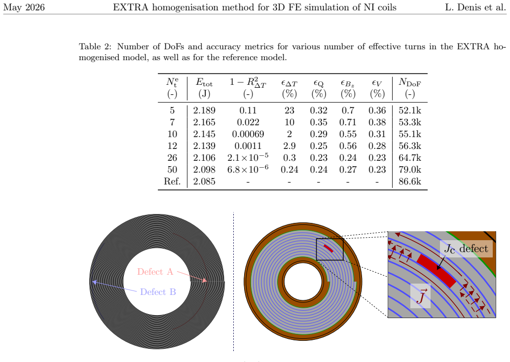
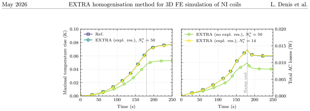
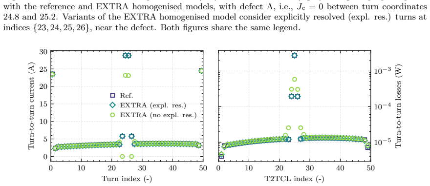
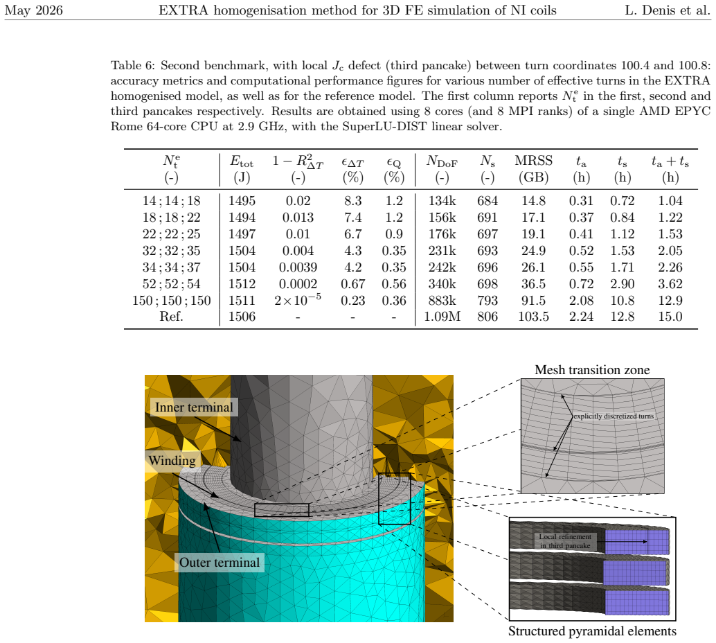
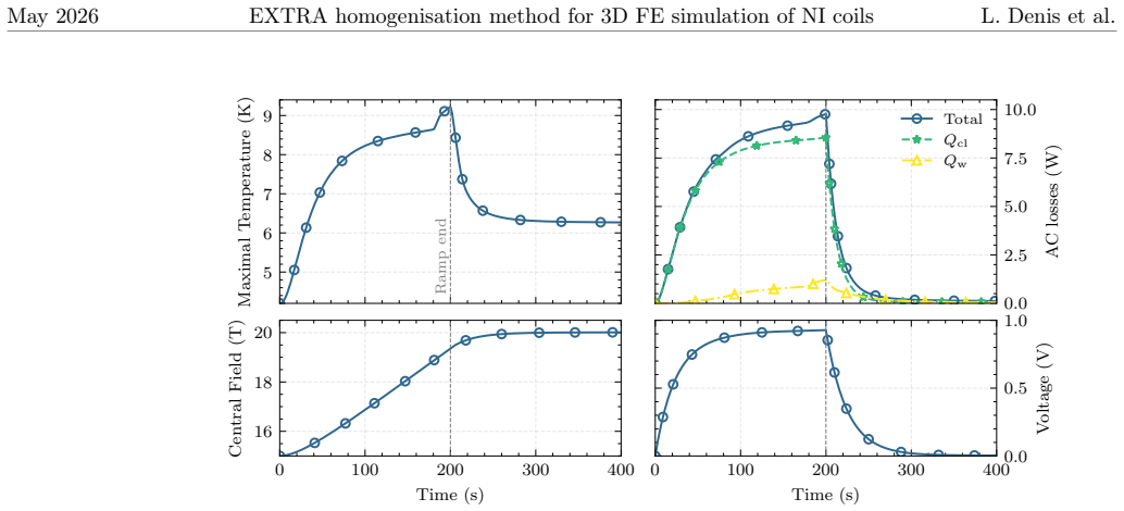
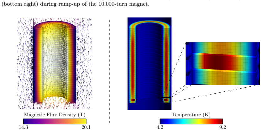
The EXTRA method enables 3D magneto-thermal finite-element simulations of large-scale no-insulation HTS magnets by explicitly resolving the inner- and outermost winding turns and adjacent contact layers, along with those next to defects, while applying anisotropic homogenization to all other turns and turn-to-turn contact layers. Resolved contact layers use the surface contact approximation. On a 50-turn single pancake the method reproduces AC losses and temperature distributions from a turn-resolved reference model. For a stack of three 150-turn pancakes computation time falls by a factor of up to 13. Results are shown for an insert magnet containing 10,000 turns.
What carries the argument
The EXTRA method, which selectively resolves specific turn-to-turn contact layers explicitly while applying anisotropic homogenization to the bulk of the winding and layers.
If this is right
- Current distribution near current leads is captured accurately enough for defect studies in large magnets.
- Thermal runaway behavior can be modeled in 3D for stacks of pancake coils at practical cost.
- Magnets with 10,000 turns become accessible to full 3D magneto-thermal analysis.
- Computation time reductions of roughly an order of magnitude are achieved relative to fully resolved models.
- The surface contact approximation for resolved layers preserves accuracy while lowering mesh size.
Where Pith is reading between the lines
- The selective explicit resolution pattern may extend to other layered conductors where only boundary or defect regions dominate the global response.
- The same homogenization-plus-explicit strategy could be tested on metal-insulation windings that exhibit comparable contact resistance ranges.
- Coupling the method to time-stepping optimization routines might allow rapid evaluation of defect placement during magnet design.
- Open availability of the input files suggests the approach can serve as a baseline for comparing alternative homogenization schemes.
Load-bearing premise
That explicitly resolving only the inner- and outermost turns and those next to defects is enough to capture the essential current distribution near leads and defects while the anisotropic homogenization of the rest remains accurate.
What would settle it
A direct comparison on a 150-turn pancake stack in which a fully turn-resolved 3D model produces current paths or local temperature rise near a defect that differ markedly from the EXTRA predictions.
Figures
read the original abstract
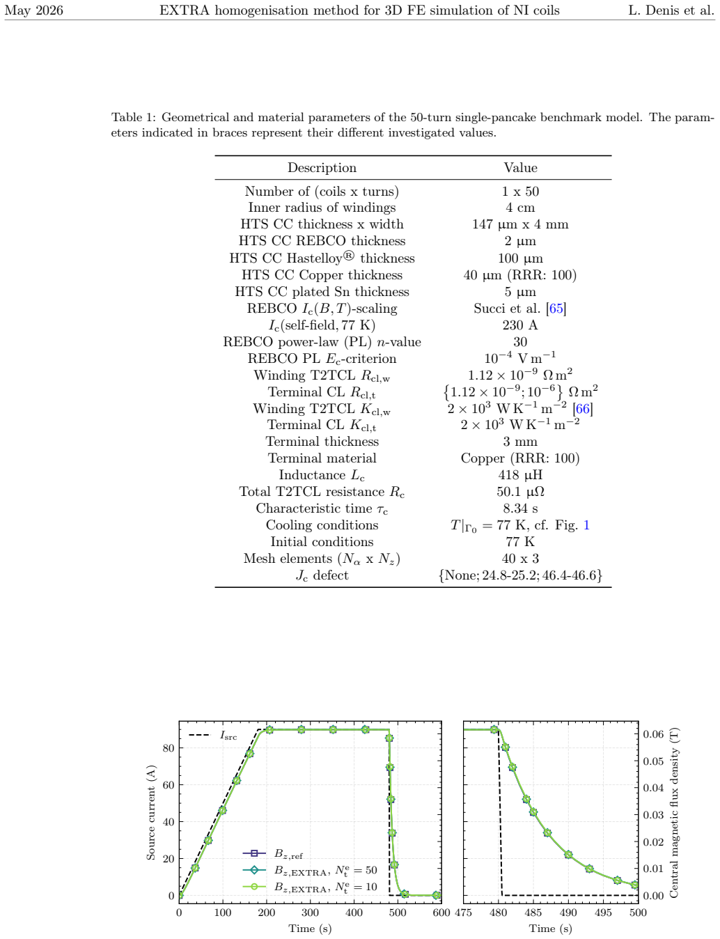
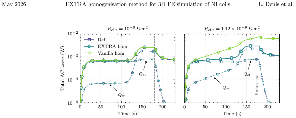
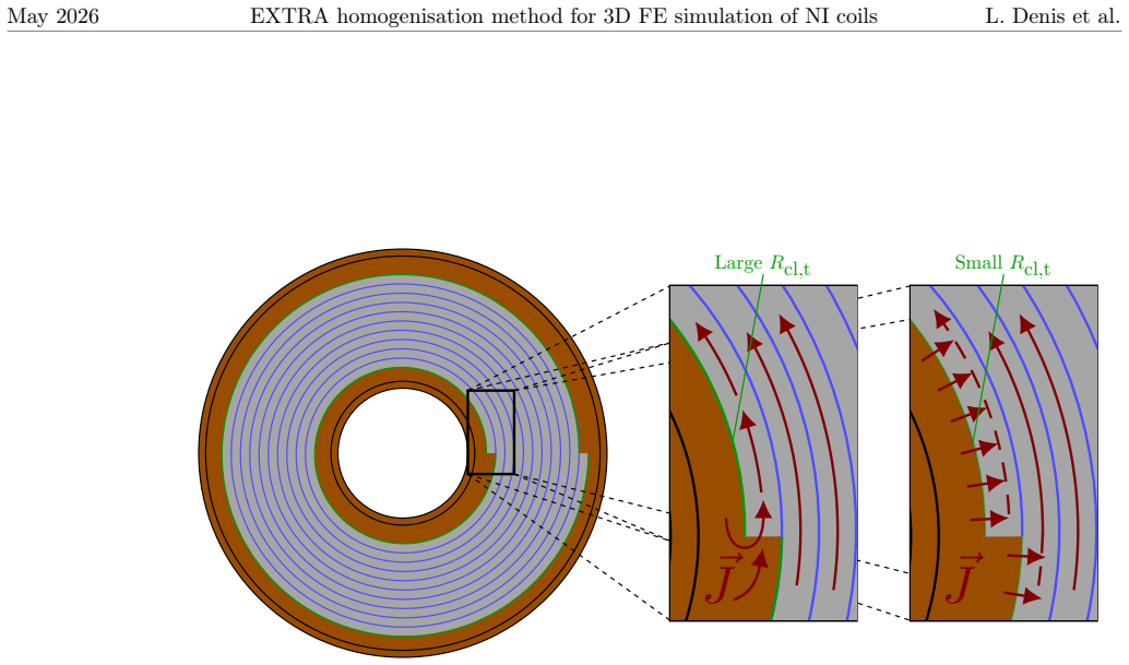
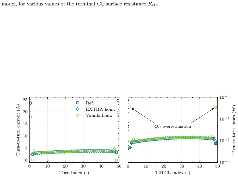
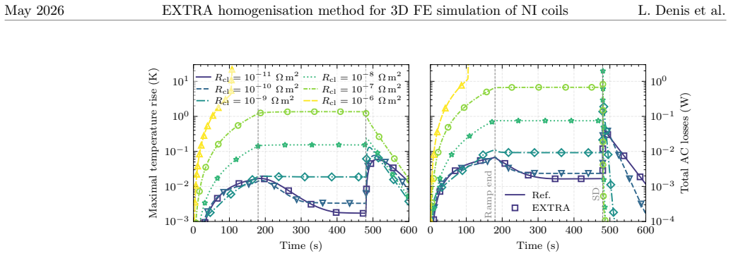
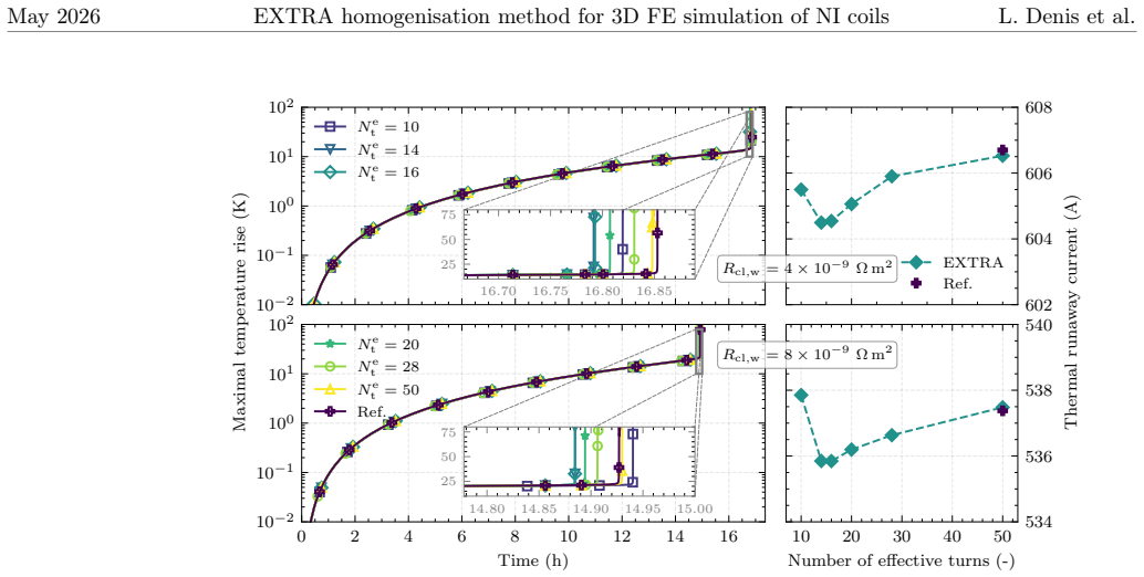
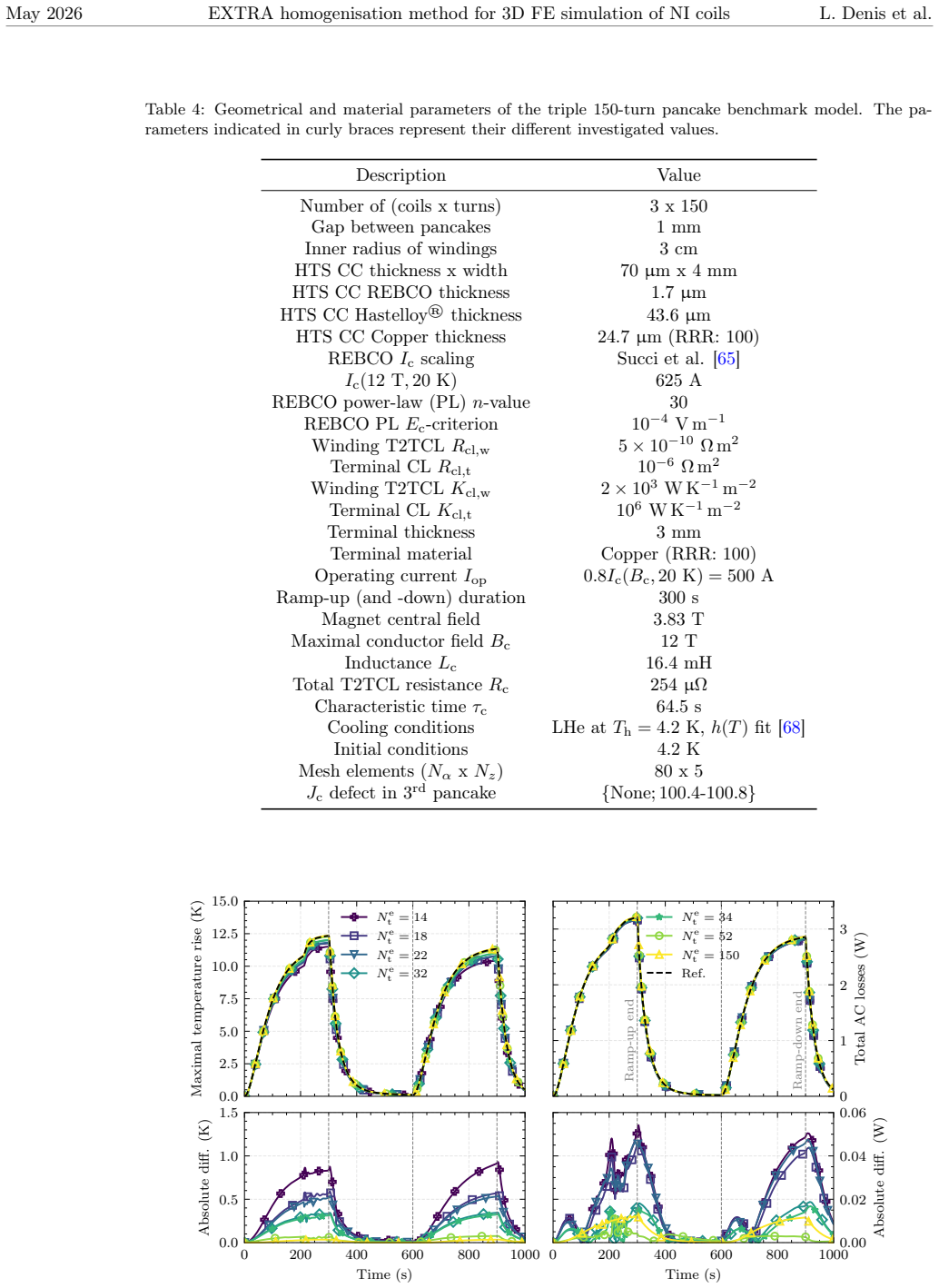
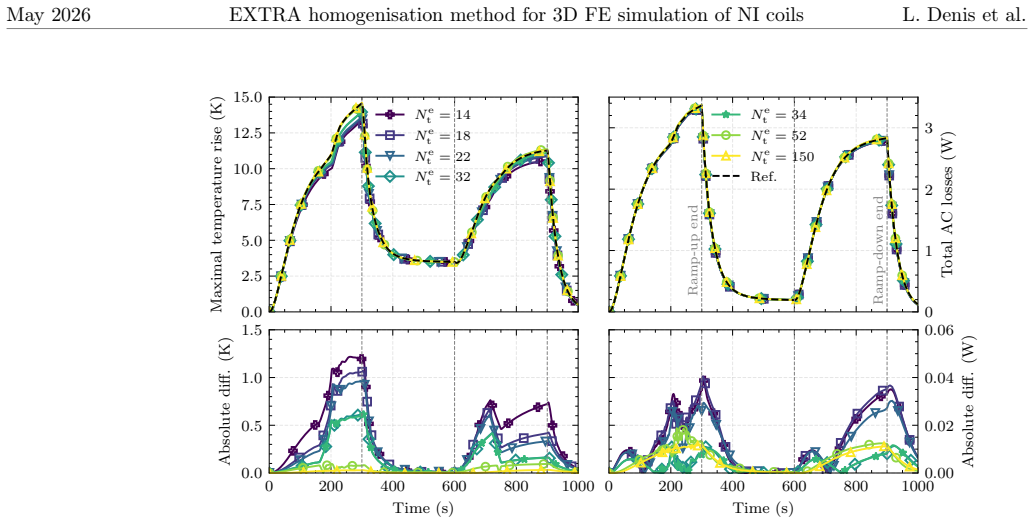
No-insulation (NI) and metal-insulation (MI) high-temperature superconducting (HTS) magnets require three-dimensional (3D) models to describe the current distribution around critical current defects. In this work, we design and validate the EXTRA homogenisation method, standing for explicit turn resolution with anisotropic homogenisation method. It allows 3D magneto-thermal finite-element (FE) simulations of large-scale magnets to be performed with high accuracy at a reasonable computational cost. The method combines the anisotropic homogenisation of turn-to-turn contact layers (T2TCLs) and their neighbouring winding turns with the explicit resolution of specific T2TCLs. In particular, the inner- and outermost winding turns and adjacent contact layers are explicitly resolved to properly describe the current distribution near current leads. In addition, the method is able to simulate local $J_{\textrm{c}}$ defects for a broad range of turn-to-turn contact resistances, provided the winding turns and T2TCLs next to the defect are explicitly resolved. For efficiency, the resolved T2TCLs are modelled using the surface contact approximation. The consistency of the proposed method is first verified on a 50-turn single pancake benchmark. It is shown to reproduce AC losses and temperature distributions obtained with a turn-resolved FE reference model, for both nominal operation and during thermal runaway. The computational efficiency of the EXTRA method is demonstrated with the simulation of a stack of three 150-turn pancake coils, for which computation time is reduced by a factor of up to 13 with respect to a turn-resolved FE reference model. Finally, the results of a large-scale 3D FE simulation, currently out of reach of turn-resolved models, are provided for an insert HTS magnet with 10,000 turns. The EXTRA method is open-source and input files to reproduce all results are made available.
Editorial analysis
A structured set of objections, weighed in public.
Referee Report
Summary. The paper introduces the EXTRA method, which combines anisotropic homogenization of interior turn-to-turn contact layers (T2TCLs) and winding turns with explicit resolution of inner/outermost turns, adjacent layers, and defect-adjacent regions (using surface-contact approximation for resolved T2TCLs). It claims this enables accurate 3D magneto-thermal FE simulations of large NI HTS magnets at reduced cost. Validation on a 50-turn pancake reproduces AC losses and temperature distributions from a turn-resolved reference for nominal operation and thermal runaway. Efficiency is shown on a 450-turn stack (up to 13x speedup), with a demonstration on a 10,000-turn insert magnet.
Significance. If the accuracy of the homogenization holds when scaling beyond the validated regime, the method would enable 3D simulations of defect behavior and thermal runaway in magnets with thousands of turns that are currently intractable with turn-resolved models. The open-source release and provision of input files for all results are positive for reproducibility.
major comments (2)
- [large-scale demonstration / 10,000-turn insert magnet] The central accuracy claim for the 10,000-turn demonstration rests on unverified extrapolation: the 50-turn benchmark provides a reference solution, but the 10k-turn case has none, so any growth of homogenization error with stack height, coupling to thermal runaway, or effects on lead-current paths cannot be quantified (see abstract description of the large-scale simulation).
- [method description / resolved T2TCLs] The surface-contact approximation for explicitly resolved T2TCLs is presented as an efficiency choice, but its modeling error is only assessed within the 50-turn benchmark; no separate convergence or sensitivity test is reported for the 450-turn or 10k-turn cases where it could affect overall current distribution.
Simulated Author's Rebuttal
We thank the referee for the constructive review and detailed comments. We address each major comment point by point below, with proposed revisions where the manuscript can be strengthened.
read point-by-point responses
-
Referee: [large-scale demonstration / 10,000-turn insert magnet] The central accuracy claim for the 10,000-turn demonstration rests on unverified extrapolation: the 50-turn benchmark provides a reference solution, but the 10k-turn case has none, so any growth of homogenization error with stack height, coupling to thermal runaway, or effects on lead-current paths cannot be quantified (see abstract description of the large-scale simulation).
Authors: We agree that no turn-resolved reference exists for the 10,000-turn case, as such a simulation remains computationally intractable. The EXTRA method explicitly resolves all regions governing lead currents and defect bypass (inner/outermost turns, adjacent T2TCLs, and defect neighborhoods), while homogenization is restricted to interior volumes whose local error was bounded in the 50-turn benchmark. The 450-turn stack provides an intermediate check that global quantities remain consistent. We will revise the abstract and conclusion to state that the 10,000-turn result demonstrates computational reach and qualitative behavior rather than claiming quantified accuracy beyond the validated regime. revision: yes
-
Referee: [method description / resolved T2TCLs] The surface-contact approximation for explicitly resolved T2TCLs is presented as an efficiency choice, but its modeling error is only assessed within the 50-turn benchmark; no separate convergence or sensitivity test is reported for the 450-turn or 10k-turn cases where it could affect overall current distribution.
Authors: The surface-contact approximation error was quantified only against the 50-turn reference. Because the number of explicitly resolved T2TCLs stays small and localized (near leads and defects) even at larger scales, the local modeling discrepancy is not expected to propagate differently. Nevertheless, we accept that an explicit sensitivity study on the larger geometries would be valuable. We will add a short paragraph in the methods or results section discussing the expected invariance of the approximation error with stack size, supported by the existing benchmark data. revision: partial
- A direct turn-resolved reference solution for the 10,000-turn magnet cannot be generated with present computational resources, so the magnitude of any scale-dependent homogenization error cannot be measured.
Circularity Check
No circularity: method validated against independent turn-resolved references
full rationale
The EXTRA method is a numerical homogenization technique whose accuracy is checked by direct comparison to separate turn-resolved FE models on the 50-turn benchmark (reproducing AC losses and temperature distributions). The 10k-turn demonstration is presented as an application without any fitted parameter or self-citation chain that reduces the claimed accuracy back to the target data by construction. All load-bearing steps rely on external reference solutions rather than internal redefinition or renaming.
Axiom & Free-Parameter Ledger
axioms (2)
- standard math Finite-element discretization and coupling of magneto-thermal equations are valid for this geometry
- domain assumption Anisotropic homogenization of turn-to-turn contact layers and neighboring turns accurately represents averaged behavior away from leads and defects
Reference graph
Works this paper leans on
-
[1]
High-temperature superconductors and their large-scale applications,
T. A. Coombs et al., “High-temperature superconductors and their large-scale applications,” Nat. Rev. Electr. Eng., vol. 1, no. 12, pp. 788–801, Dec. 2024.doi: 10.1038/s44287-024-00112-y
-
[2]
Reel-to-reel critical current measurement of coated conductors,
S. Furtner, R. Nemetschek, R. Semerad, G. Sigl, and W. Prusseit, “Reel-to-reel critical current measurement of coated conductors,”Supercond. Sci. Technol., vol. 17, no. 5, S281, Mar. 2004.doi:10.1088/0953-2048/17/5/037
-
[3]
Stability of DC transport in HTS conductor with local critical current reduction,
F. Gömöry and J. Šouc, “Stability of DC transport in HTS conductor with local critical current reduction,”Supercond. Sci. Technol., vol. 34, no. 2, p. 025005, Jan. 2021.doi: 10.1088/1361-6668/abc73e
-
[4]
F. Gömöry and J. Šouc, “Analysis of current and heat transfer in locations with reduced critical current in coated conductor tape,”Supercond. Sci. Technol., vol. 37, no. 9, p. 095017, Aug. 2024.doi:10.1088/1361-6668/ad6484
-
[5]
M. Wozniak et al., “Influence of Critical Current Defect on Operation, Quench Detection and Protection of a Conduction-Cooled Pancake REBCO Coil,”IEEE Trans. Appl. Supercond., vol. 35, no. 5, pp. 1–6, Aug. 2025.doi:10.1109/TASC.2025.3532246
-
[6]
Quench Detection and Protection for High-Temperature Superconductor Accelerator Magnets,
M. Marchevsky, “Quench Detection and Protection for High-Temperature Superconductor Accelerator Magnets,”Instruments, vol. 5, no. 3, p. 27, Sep. 2021.doi: 10.3390/instruments5030027
-
[7]
HTS Pancake Coils Without Turn-to-Turn Insulation,
S. Hahn, D. K. Park, J. Bascunan, and Y. Iwasa, “HTS Pancake Coils Without Turn-to-Turn Insulation,”IEEE Trans. Appl. Supercond., vol. 21, no. 3, pp. 1592–1595, Jun. 2011.doi: 10.1109/TASC.2010.2093492
-
[8]
Current Status of and Challenges for No-Insulation HTS Winding Technique,
S. Hahn, “Current Status of and Challenges for No-Insulation HTS Winding Technique,” TEION KOGAKU, vol. 53, no. 1, pp. 2–9, Mar. 2018.doi:10.2221/jcsj.53.2
-
[9]
Basic mechanism of self-healing from thermal runaway for uninsulated REBCO pancake coils,
Y. Yanagisawa et al., “Basic mechanism of self-healing from thermal runaway for uninsulated REBCO pancake coils,”Physica C: Superconductivity, vol. 499, pp. 40–44, Apr. 2014.doi: 10.1016/j.physc.2014.02.002
-
[10]
A (RE)BCO Pancake Winding With Metal-as-Insulation,
T. Lécrevisse and Y. Iwasa, “A (RE)BCO Pancake Winding With Metal-as-Insulation,”IEEE Trans. Appl. Supercond., vol. 26, no. 3, pp. 1–5, Apr. 2016.doi: 10.1109/TASC.2016.2522638
-
[11]
Filled Thermoplastic Based Coating for Tailored Contact Resistance in HTS Coils,
M. Crescenti et al., “Filled Thermoplastic Based Coating for Tailored Contact Resistance in HTS Coils,”IEEE Trans. Appl. Supercond., vol. 36, no. 5, pp. 1–5, Aug. 2026.doi: 10.1109/TASC.2026.3656161
-
[12]
The normal-zone propagation properties of the non-insulated HTS coil in cryocooled operation,
S. Kim, A. Saitou, J. Joo, and T. Kadota, “The normal-zone propagation properties of the non-insulated HTS coil in cryocooled operation,”Physica C: Superconductivity and its Applications, vol. 471, no. 21-22, pp. 1428–1431, Nov. 2011.doi: 10.1016/j.physc.2011.05.209
-
[13]
Y. Wang, H. Song, W. Yuan, Z. Jin, and Z. Hong, “Ramping turn-to-turn loss and magnetization loss of a No-Insulation (RE)Ba2Cu3Ox high temperature superconductor pancake coil,”J. Appl. Phys., vol. 121, no. 11, p. 113903, Mar. 2017.doi: 10.1063/1.4978593
-
[14]
45.5-Tesla direct-current magnetic field generated with a high-temperature superconducting magnet,
S. Hahn et al., “45.5-tesla direct-current magnetic field generated with a high-temperature superconducting magnet,”Nature, vol. 570, no. 7762, pp. 496–499, Jun. 2019.doi: 10.1038/s41586-019-1293-1
-
[15]
Quench and self-protecting behaviour of an intra-layer no-insulation (LNI) REBCO coil at 31.4 T,
Y. Suetomi et al., “Quench and self-protecting behaviour of an intra-layer no-insulation (LNI) REBCO coil at 31.4 T,”Supercond. Sci. Technol., vol. 34, no. 6, p. 064003, Apr. 2021.doi: 10.1088/1361-6668/abf54e
-
[16]
Degradation Characteristics of a 20 T REBCO Insert Magnet After a 4.2 K Standalone Test,
L. Shao et al., “Degradation Characteristics of a 20 T REBCO Insert Magnet After a 4.2 K Standalone Test,”IEEE Trans. Appl. Supercond., vol. 33, no. 5, pp. 1–6, Aug. 2023.doi: 10.1109/TASC.2023.3254483
-
[17]
X. Wang et al., “Turn-to-turn contact characteristics for an equivalent circuit model of no-insulation ReBCO pancake coil,”Supercond. Sci. Technol., vol. 26, no. 3, p. 035012, Jan. 2013.doi:10.1088/0953-2048/26/3/035012
-
[18]
An equivalent circuit grid model for no-insulation HTS pancake coils,
Y. Wang, H. Song, D. Xu, Z. Y. Li, Z. Jin, and Z. Hong, “An equivalent circuit grid model for no-insulation HTS pancake coils,”Supercond. Sci. Technol., vol. 28, no. 4, p. 045017, Mar. 2015.doi:10.1088/0953-2048/28/4/045017 27 May 2026 EXTRA homogenisation method for 3D FE simulation of NI coils L. Denis et al
-
[19]
T. Wang et al., “Analyses of Transient Behaviors of No-Insulation REBCO Pancake Coils During Sudden Discharging and Overcurrent,”IEEE Trans. Appl. Supercond., vol. 25, no. 3, pp. 1–9, Jun. 2015.doi:10.1109/TASC.2015.2393058
-
[20]
Finite-element modelling of no-insulation HTS coils using rotated anisotropic resistivity,
R. C. Mataira, M. D. Ainslie, R. A. Badcock, and C. W. Bumby, “Finite-element modelling of no-insulation HTS coils using rotated anisotropic resistivity,”Supercond. Sci. Technol., vol. 33, no. 8, 08LT01, Jun. 2020.doi:10.1088/1361-6668/ab9688
-
[21]
From Modelling to Application: Exploring Quench Tolerance in High-Field HTS Magnets,
E.-K. C. Brewerton et al., “From Modelling to Application: Exploring Quench Tolerance in High-Field HTS Magnets,”IEEE Trans. Appl. Supercond., vol. 36, no. 3, pp. 1–6, May 2026. doi:10.1109/TASC.2025.3635639
-
[22]
Fast and accurate electromagnetic modeling of non-insulated and metal-insulated REBCO magnets,
E. Pardo and P. Fazilleau, “Fast and accurate electromagnetic modeling of non-insulated and metal-insulated REBCO magnets,”Supercond. Sci. Technol., vol. 37, no. 3, p. 035016, Feb. 2024.doi:10.1088/1361-6668/ad1c6f
-
[23]
Screening currents increase thermal quench propagation speed in ultra-high-field REBCO magnets,
E. Pardo, A. Dadhich, N. Jerance, and P. Fazilleau, “Screening currents increase thermal quench propagation speed in ultra-high-field REBCO magnets,”Results in Engineering, vol. 29, p. 108933, Mar. 2026.doi:10.1016/j.rineng.2025.108933
-
[24]
Magnetization loss of no-insulation coil for an electrodynamic suspension system,
X. Wang et al., “Magnetization loss of no-insulation coil for an electrodynamic suspension system,”Supercond. Sci. Technol., vol. 34, no. 6, p. 065007, May 2021.doi: 10.1088/1361-6668/abe18c
-
[25]
W. Zhao, Y. Lu, D. Zhou, C. Bai, Q. Li, and C. Cai, “Numerical Study on Thermal Stability of No-Insulation Coils Using a Three-Dimensional Finite-Element Model,”IEEE Trans. Appl. Supercond., vol. 32, no. 5, pp. 1–10, Aug. 2022.doi:10.1109/TASC.2022.3175749
-
[26]
Electromag- netic simulation of no-insulation coils using h-ϕthin shell approxima- tion,
E. Schnaubelt, M. Wozniak, S. Schöps, and A. Verweij, “Electromagnetic Simulation of No-Insulation Coils Using H – Phi Thin Shell Approximation,”IEEE Trans. Appl. Supercond., vol. 33, no. 5, pp. 1–6, Aug. 2023.doi:10.1109/TASC.2023.3258905
-
[27]
Thermal thin shell approx- imation towards finite element quench simulation,
E. Schnaubelt, M. Wozniak, and S. Schöps, “Thermal thin shell approximation towards finite element quench simulation,”Supercond. Sci. Technol., vol. 36, no. 4, p. 044004, Mar. 2023. doi:10.1088/1361-6668/acbeea
-
[28]
Magneto-thermal thin shell approximation for 3D finite element analysis of no-insulation coils,
E. Schnaubelt et al., “Magneto-Thermal Thin Shell Approximation for 3D Finite Element Analysis of No-Insulation Coils,”IEEE Trans. Appl. Supercond., vol. 34, no. 3, pp. 1–6, May 2024.doi:10.1109/TASC.2023.3340648
-
[29]
S. Wang, H. Yong, and Y. Zhou, “Modeling of contact resistivity and simplification of 3D homogenization strategy for the H formulation,”Supercond. Sci. Technol., vol. 37, no. 7, p. 075019, Jun. 2024.doi:10.1088/1361-6668/ad541f
-
[30]
Z. Zhong, W. Wu, G. Ma, and Z. Jin, “Study of the demagnetization behavior of no-insulation persistent-current mode HTS coils under external AC fields by 3D FEM simulation,”Supercond. Sci. Technol., vol. 37, no. 4, p. 045011, Mar. 2024.doi: 10.1088/1361-6668/ad2300
-
[31]
Z. Zhong, W. Wu, and Z. Jin, “Fast and accurate 3D FEM model for electromagnetic simulations of no-insulation HTS coils based on polygon-anisotropic-resistivity,”Supercond. Sci. Technol., vol. 37, no. 9, 09LT01, Aug. 2024.doi:10.1088/1361-6668/ad68d6
-
[32]
B. G. Koshy et al., “Magnetisation loss behaviour in insulated and non-insulated HTS REBCO double-pancake and racetrack coils at 77 K,”Supercond. Sci. Technol., vol. 38, no. 4, p. 045004, Mar. 2025.doi:10.1088/1361-6668/adbce2
-
[33]
Electromagnetic modeling of no-insulation REBCO coils based on T–A formulation: From 2D to 3D,
Y. Chen et al., “Electromagnetic modeling of no-insulation REBCO coils based on T–A formulation: From 2D to 3D,”Supercond. Sci. Technol., vol. 39, no. 2, p. 025005, Feb. 2026. doi:10.1088/1361-6668/ae3a1e
-
[34]
Enhanced Model for Non-Insulated HTS Coils,
S. Sorti, L. Balconi, G. Crespi, L. Rossi, C. Santini, and M. Statera, “Enhanced Model for Non-Insulated HTS Coils,”IEEE Trans. Appl. Supercond., vol. 35, no. 5, pp. 1–5, Aug. 2025. doi:10.1109/TASC.2025.3546873
-
[35]
T. Mulder et al., “Thermo-Electromagnetic Design, Operation, and Protection Simulations of a 40 T HTS NI Final Cooling Solenoid for a Muon Collider,”IEEE Trans. Appl. Supercond., vol. 35, no. 5, pp. 1–5, Aug. 2025.doi:10.1109/TASC.2025.3530379
-
[36]
V. M. R. Zermeno, A. B. Abrahamsen, N. Mijatovic, B. B. Jensen, and M. P. Sørensen, “Calculation of alternating current losses in stacks and coils made of second generation high temperature superconducting tapes for large scale applications,”Journal of Applied Physics, vol. 114, no. 17, p. 173901, Nov. 2013.doi:10.1063/1.4827375 28 May 2026 EXTRA homogeni...
-
[37]
3D modeling and simulation of 2G HTS stacks and coils,
V. M. R. Zermeño and F. Grilli, “3D modeling and simulation of 2G HTS stacks and coils,” Supercond. Sci. Technol., vol. 27, no. 4, p. 044025, Mar. 2014.doi: 10.1088/0953-2048/27/4/044025
-
[38]
Numerical models for ac loss calculation in large-scale applications of HTS coated conductors,
L. Quéval, V. M. R. Zermeño, and F. Grilli, “Numerical models for ac loss calculation in large-scale applications of HTS coated conductors,”Supercond. Sci. Technol., vol. 29, no. 2, p. 024007, Feb. 2016.doi:10.1088/0953-2048/29/2/024007
-
[39]
E. Berrospe-Juarez, F. Trillaud, V. M. R. Zermeño, and F. Grilli, “Advanced electromagnetic modeling of large-scale high-temperature superconductor systems based on H and T-A formulations,”Supercond. Sci. Technol., vol. 34, no. 4, p. 044002, Feb. 2021.doi: 10.1088/1361-6668/abde87
-
[40]
3D homogenization of the T-A formulation for the analysis of coils with complex geometries,
C. R. Vargas-Llanos, F. Huber, N. Riva, M. Zhang, and F. Grilli, “3D homogenization of the T-A formulation for the analysis of coils with complex geometries,”Supercond. Sci. Technol., vol. 35, no. 12, p. 124001, Oct. 2022.doi:10.1088/1361-6668/ac9932
-
[41]
Use of the J-A Approach to Model Homogenized 2G Tape Stacks and HTS Bulks,
B. M. O. Santos, G. dos Santos, F. G. d. R. Martins, F. Sass, G. G. Sotelo, and R. de Andrade, “Use of the J-A Approach to Model Homogenized 2G Tape Stacks and HTS Bulks,” IEEE Trans. Appl. Supercond., vol. 34, no. 3, pp. 1–5, May 2024.doi: 10.1109/TASC.2024.3356495
-
[42]
Foil Conductor Model for Efficient Simulation of HTS Coils in Large Scale Applications,
E. Paakkunainen, L. Denis, C. Geuzaine, P. Rasilo, and S. Schöps, “Foil Conductor Model for Efficient Simulation of HTS Coils in Large Scale Applications,”IEEE Trans. Appl. Supercond., vol. 35, no. 5, pp. 1–5, Aug. 2025.doi:10.1109/TASC.2024.3517573
-
[43]
Magnetic Field Conforming Formulations for Foil Windings,
L. Denis, E. Paakkunainen, P. Rasilo, S. Schöps, B. Vanderheyden, and C. Geuzaine, “Magnetic Field Conforming Formulations for Foil Windings,”IEEE Trans. Magn., vol. 61, no. 8, pp. 1–7, Aug. 2025.doi:10.1109/TMAG.2025.3584111
-
[44]
E. Paakkunainen, L. Denis, B. Vanderheyden, C. Geuzaine, P. Rasilo, and S. Schöps, Homogenization of HTS coils with the h, h-phi, and t-omega foil conductor model, Mar. 2026. doi:10.48550/arXiv.2604.00154arXiv:2604.00154 [cs]
work page doi:10.48550/arxiv.2604.00154arxiv:2604.00154 2026
-
[45]
L. Wang and J. Zheng, “3D general simultaneous multi-scale homogeneous T-A model for electromagnetic simulations of large-scale REBCO coils with complex geometries,”Supercond. Sci. Technol., vol. 38, no. 8, p. 085005, Aug. 2025.doi:10.1088/1361-6668/adef88
-
[46]
L. Denis, B. Vanderheyden, and C. Geuzaine, “Simultaneous Multi-Scale Homogeneous H-Phi Thin-Shell Model for Efficient Simulations of Stacked HTS Coils,”IEEE Trans. Appl. Supercond., vol. 36, no. 5, pp. 1–7, Aug. 2026.doi:10.1109/TASC.2026.3652981
-
[47]
Surface Contact Approximation for Magneto-Thermal Finite Element Analysis of No-Insulation HTS Coils
E. Schnaubelt, L. Denis, M. Wozniak, J. Dular, and A. Verweij,Surface Contact Approximation for Magneto-Thermal Finite Element Analysis of No-Insulation HTS Coils, 2026.doi:10.48550/arXiv.2605.28574arXiv:2605.28574
work page internal anchor Pith review Pith/arXiv arXiv doi:10.48550/arxiv.2605.28574arxiv:2605.28574 2026
-
[48]
E. Schnaubelt, “Models and Methods for Transient Magneto-Thermal Finite Element Simulation of Superconducting Magnets,” Ph.D. dissertation, TU Darmstadt, May 2025.doi: 10.26083/tuprints-00031402
-
[49]
Homology and cohomology computation in finite element modeling,
M. Pellikka, S. Suuriniemi, L. Kettunen, and C. Geuzaine, “Homology and Cohomology Computation in Finite Element Modeling,”SIAM J. Sci. Comput., Oct. 2013.doi: 10.1137/130906556
-
[50]
Critical Persistent Currents in Hard Superconductors,
Y. B. Kim, C. F. Hempstead, and A. R. Strnad, “Critical Persistent Currents in Hard Superconductors,”Phys. Rev. Lett., vol. 9, no. 7, pp. 306–309, Oct. 1962.doi: 10.1103/PhysRevLett.9.306
-
[51]
Theory of Flux Creep in Hard Superconductors,
P. W. Anderson, “Theory of Flux Creep in Hard Superconductors,”Phys. Rev. Lett., vol. 9, no. 7, pp. 309–311, Oct. 1962.doi:10.1103/PhysRevLett.9.309
-
[52]
L. Bortot et al., “A Coupled A–H Formulation for Magneto-Thermal Transients in High-Temperature Superconducting Magnets,”IEEE Trans. Appl. Supercond., vol. 30, no. 5, pp. 1–11, Aug. 2020.doi:10.1109/TASC.2020.2969476
-
[53]
An Open-Source Finite Element Quench Simulation Tool for Superconducting Magnets,
A. Vitrano, M. Wozniak, E. Schnaubelt, T. Mulder, E. Ravaioli, and A. Verweij, “An Open-Source Finite Element Quench Simulation Tool for Superconducting Magnets,”IEEE Trans. Appl. Supercond., vol. 33, no. 5, pp. 1–6, Aug. 2023.doi: 10.1109/TASC.2023.3259332
-
[54]
An open-source 3D FE quench simulation tool for no-insulation HTS pancake coils,
S. Atalay et al., “An open-source 3D FE quench simulation tool for no-insulation HTS pancake coils,”Supercond. Sci. Technol., vol. 37, no. 6, p. 065005, May 2024.doi: 10.1088/1361-6668/ad3f83 29 May 2026 EXTRA homogenisation method for 3D FE simulation of NI coils L. Denis et al
-
[55]
C. Geuzaine and J.-F. Remacle, “Gmsh: A 3-D finite element mesh generator with built-in pre- and post-processing facilities,”Int. J. Numer. Methods Eng., vol. 79, no. 11, pp. 1309–1331, May 2009.doi:10.1002/nme.2579
-
[56]
Schnaubelt and L
E. Schnaubelt and L. Denis,CERNGetDP 2026.4.4, https://gitlab.cern.ch/steam/cerngetdp/-/releases/2026.4.4, Apr. 2026
2026
-
[57]
P. Dular, C. Geuzaine, F. Henrotte, and W. Legros, “A general environment for the treatment of discrete problems and its application to the finite element method,”IEEE Trans. Magn., vol. 34, no. 5, pp. 3395–3398, Sep. 1998.doi:10.1109/20.717799
-
[58]
Denis and E
L. Denis and E. Schnaubelt,STEAM SDK Analysis for ’Explicit Turn Resolution with Anisotropic Homogenisation for Efficient 3D Magneto-Thermal Finite-Element Simulation of Large-Scale No-Insulation HTS Magnets’, https://gitlab.cern.ch/steam/analyses/anisotropic- homogenization-of-ni-hts-magnets/-/tags/initial_arxiv_submission, May 2026
2026
-
[59]
MUMPS: A General Purpose Distributed Memory Sparse Solver,
P. R. Amestoy, I. S. Duff, J.-Y. L’Excellent, and J. Koster, “MUMPS: A General Purpose Distributed Memory Sparse Solver,” inApplied Parallel Computing. New Paradigms for HPC in Industry and Academia, T. Sørevik, F. Manne, A. H. Gebremedhin, and R. Moe, Eds., Berlin, Heidelberg: Springer, 2001, pp. 121–130.doi:10.1007/3-540-70734-4_16
-
[60]
SuperLU_DIST: A scalable distributed-memory sparse direct solver for unsymmetric linear systems,
X. S. Li and J. W. Demmel, “SuperLU_DIST: A scalable distributed-memory sparse direct solver for unsymmetric linear systems,”ACM Trans. Math. Softw., vol. 29, no. 2, pp. 110–140, Jun. 2003.doi:10.1145/779359.779361
-
[61]
Newly Released Capabilities in the Distributed-Memory SuperLU Sparse Direct Solver,
X. S. Li, P. Lin, Y. Liu, and P. Sao, “Newly Released Capabilities in the Distributed-Memory SuperLU Sparse Direct Solver,”ACM Trans. Math. Softw., vol. 49, no. 1, 10:1–10:20, Mar. 2023.doi:10.1145/3577197
-
[62]
Efficient Management of Parallelism in Object-Oriented Numerical Software Libraries,
S. Balay, W. D. Gropp, L. C. McInnes, and B. F. Smith, “Efficient Management of Parallelism in Object-Oriented Numerical Software Libraries,” inModern Software Tools for Scientific Computing, E. Arge, A. M. Bruaset, and H. P. Langtangen, Eds., Boston, MA: Birkhäuser, 1997, pp. 163–202.doi:10.1007/978-1-4612-1986-6_8
-
[63]
Investigation on the electrical contact resistance of soldered metal insulation REBCO coil,
J. Lee, J. Mun, J. Kim, and S. Kim, “Investigation on the Electrical Contact Resistance of Soldered Metal Insulation REBCO Coil,”IEEE Trans. Appl. Supercond., vol. 31, no. 5, pp. 1–5, Aug. 2021.doi:10.1109/TASC.2021.3063653
-
[64]
No-Insulation Coil Under Time-Varying Condition: Magnetic Coupling With External Coil,
S. Hahn et al., “No-Insulation Coil Under Time-Varying Condition: Magnetic Coupling With External Coil,”IEEE Trans. Appl. Supercond., vol. 23, no. 3, pp. 4601705–4601705, Jun. 2013.doi:10.1109/TASC.2013.2240756
-
[65]
Mag- netic field and temperature scaling of the critical current of REBCO tapes,
G. Succi, A. Ballarino, S. C. Hopkins, C. Barth, and Y. Yang, “Magnetic Field and Temperature Scaling of the Critical Current of REBCO Tapes,”IEEE Trans. Appl. Supercond., vol. 34, no. 3, pp. 1–7, May 2024.doi:10.1109/TASC.2024.3370137
-
[66]
Overall thermal conductance and thermal contact resistance in no-insulation REBCO magnet,
J. Seok, D. Kim, and S. Kim, “Overall Thermal Conductance and Thermal Contact Resistance in No-Insulation REBCO Magnet,”IEEE Trans. Appl. Supercond., vol. 28, no. 3, pp. 1–5, Apr. 2018.doi:10.1109/TASC.2017.2785825
-
[67]
T. H. Nes et al., “Effective Time Constants at 4.2 to 70 K in ReBCO Pancake Coils With Different Inter-Turn Resistances,”IEEE Trans. Appl. Supercond., vol. 32, no. 4, pp. 1–6, Jun. 2022.doi:10.1109/TASC.2022.3148968
-
[68]
A. P. Verweij, “CUDI: A model for calculation of electrodynamic and thermal behaviour of superconducting Rutherford cables,”Cryogenics, This Issue Contains Papers from CHATS-2005: Workshop on Computation of Thermohydraulic Transients in Superconductors, vol. 46, no. 7, pp. 619–626, Jul. 2006.doi:10.1016/j.cryogenics.2006.01.009
-
[69]
M. Bonura, C. Barth, A. Joudrier, J. F. Troitino, A. Fête, and C. Senatore, “Systematic Study of the Contact Resistance Between REBCO Tapes: Pressure Dependence in the Case of No-Insulation, Metal Co-Winding and Metal-Insulation,”IEEE Trans. Appl. Supercond., vol. 29, no. 5, pp. 1–5, Aug. 2019.doi:10.1109/TASC.2019.2893564 30
discussion (0)
Sign in with ORCID, Apple, or X to comment. Anyone can read and Pith papers without signing in.