REVIEW 3 major objections 6 minor 64 references
Monocular Vision-Based Swarm Robot Localization Using Equilateral Triangular Formations
T0 review · 3 major / 6 minor · reviewed 2026-08-15 · deepseek-v4-flash
Pith's one-line read Four robots arranged in equilateral triangles can localize from lateral pixel distances alone, with error per step rather than per minute, beating dead-reckoning on long missions.
desk verdict A sound geometric trick and a clean one-step experiment, but the head-to-head with dead-reckoning leans on an uncalibrated 16% wheel-scale bias that would normally be removed. read the letter →
The pith
A machine-rendered reading of the paper's core claim, the machinery that carries it, and where it could break.
The reading
What carries the argument
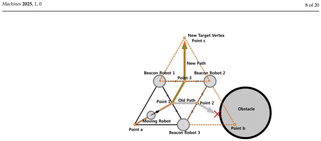
The load-bearing mechanism is the four-robot equilateral triangular formation with an anchor beacon. The beacon at the opposite vertex of the triangle serves as the anchor in the moving robot's rear-view image; the robot only needs to equalize the two lateral pixel gaps $d_{m1}$ and $d_{m2}$ between that anchor and the two base beacons, and to match those gaps to the target value $d_t$. In an equilateral triangle, satisfying $d_{m1}=d_{m2}=d_t$ in the image places the camera at the correct planar vertex, so the geometry itself performs the two-dimensional localization. This reduces the problem to reliable one-dimensional pixel counting and avoids the costly, noisy depth estimation that normally makes monocular localization hard.
What would settle it
Run a field experiment with ground truth over at least 20 consecutive triangle formations at two wheel speeds, one double the other, and compare final vertex errors: if the slower run shows a clearly larger error, if per-step errors grow as the formation advances, or if repeated steps show correlated drift, the central claim fails; the paper predicts the two speeds give nearly equal endpoint error.
Extended reading notes
Core claim
On its own terms, the central claim is that a one-dimensional measurement—the lateral pixel distance between beacon robots in a monocular image—is enough to determine a two-dimensional robot position when the formation is an equilateral triangle. Three robots hold the triangle while a fourth, the moving robot, enters through it and then uses a rear-view camera to measure $d_{m1}$ and $d_{m2}$, the lateral distances from the opposite-vertex beacon to the two near beacons. By steering so that $d_{m1}=d_{m2}=d_t$, where $d_t$ is a pre-set target disparity tied to the triangle side length, the moving robot arrives at the exact vertex of the next equilateral triangle; the paper deliberately avoids depth estimation. The paper reports single-step placement errors with means of 36 mm lateral and 13 mm longitudinal, with standard deviations of 21 mm and 9 mm, from 60 trials, and simulations based on those errors show total error scaling with the number of triangles rather than elapsed time. In the many-turn trajectory with wheel speed halved, the proposed method ends at 0.51 m error while the modeled dead-reckoning system ends at 1.43 m.
Load-bearing premise
The method assumes the initial formation is accurately set up and that the per-step placement error measured in 60 controlled single-triangle trials stays independent, uncorrelated, and unchanged over many real-world steps; if initial alignment is off or errors compound with distance, direction, or speed, the claimed edge over dead-reckoning does not transfer.
Editorial extensions
If this is right
- In open, featureless environments, a robot swarm can maintain a position estimate using only cameras and visual markers; no GPS, maps, lidar, or ranging infrastructure is needed.
- Localization error is tied to the number of triangle-formation steps, not elapsed time; a robot that slows down to save power or avoid obstacles does not pay a position-accuracy penalty.
- The four-robot scheme extends to N robots with roughly unchanged endpoint error, because the number of triangles required to reach a distant goal stays nearly the same as the swarm grows.
- Image processing stays cheap enough for a single-board computer, and robots only share path-planning information, never images, so communication bandwidth remains low.
Reading between the lines
- Inference: If the per-step errors are independent, endpoint error should grow roughly with the square root of the number of triangles, not linearly with time; this predicts that a long fast run and a short slow run covering the same number of steps should end with similar error, which can be tested directly.
- Inference: The same lateral-only trick would generalize to other regular polygons, but the equilateral triangle is the minimal shape where equalizing two projected side gaps at an anchor fixes the next vertex; testing other polygons would show how far the geometric principle extends.
- Inference: The method's practical ceiling is marker visibility and line of sight; in cluttered or occluded environments the formation would break down, so the paper's open-space advantage is also its operating boundary, and fusing with short-range obstacle sensors is a natural companion layer.
- Inference: The simulation results stand or fall on whether the 60-trial lab error model transfers to field conditions; a long outdoor run with independent ground truth would be the decisive check.
Signed reviews
Editorial analysis
A structured set of objections, weighed in public.
Referee Report
Summary. The paper proposes a cooperative localization method for a four-robot swarm operating in open, infrastructure-free environments. Three beacon robots form an equilateral triangle while a fourth 'moving' robot advances to the next vertex using only lateral pixel distances between visual markers observed with monocular cameras (Algorithm I, Section 2). The method deliberately avoids depth estimation and odometry, so the authors claim that positioning errors accumulate per formation step rather than per unit time. A 60-trial laboratory experiment with Vicon ground truth yields lateral and longitudinal per-step error statistics (means 36 mm and 13 mm; standard deviations 21 mm and 9 mm, Section 4.2), and these statistics are used in simulations of longer trajectories with many turns and a patrol path (Section 5). The proposed method is compared with a conventional dead-reckoning model based on a Gauss-Markov heading error and a wheel-speed sensor model (Eq. 3); Table 1 reports endpoint errors showing the proposed method outperforming dead-reckoning, with the advantage growing when the intended wheel speed is reduced.
Significance. If the quantitative claims hold, the paper offers an attractive low-cost, infrastructure-free localization alternative for swarm robots in open spaces, with potential applications in search and rescue. The core geometric idea--reconstructing the two-dimensional vertex of an equilateral triangle from one-dimensional lateral disparity measurements--is elegant and potentially generalizable to other multi-robot formations. The paper includes a clean single-step experimental evaluation with motion-capture ground truth, an external comparison against a dead-reckoning model, a scalability analysis for N-robot systems, and a collision-avoidance path planner. The main risk is not circularity but rather the fairness of the dead-reckoning baseline and the transferability of the fitted per-step error model to long trajectories; both issues directly affect the strength of the central claim in the abstract.
major comments (3)
- [Section 4.2, Eq. (3), and Table 1] The dead-reckoning baseline uses a wheel-speed scale factor of SF_WSS=0.16, described as experimentally estimated for the authors' Stella platform. A 16% constant scale error is a large systematic error that is normally compensated during wheel-radius calibration even in low-cost systems; a typical residual after calibration is on the order of 1-2%. Because the scale factor integrates linearly with distance traveled, it contributes a dominant, distance-proportional error to the dead-reckoning trajectories in Fig. 12 and Fig. 13 (e.g., 0.81 m at Ω=5.8 in Table 1). The paper does not show that 0.16 is a representative residual for a conventional low-cost dead-reckoning system. The central claim that the proposed method's error becomes 'significantly smaller' as travel time increases is therefore not yet established against a fair baseline. Please re-run the comparison with a calibrated scale factor (e.g., 0.01-0.02) and report a sensitivity analysis over SF_WSS.
- [Section 4.2 and Section 5] The long-trajectory simulation of the proposed method samples per-step lateral and longitudinal errors from the same Gaussian statistics fitted from 60 single-step trials in a Vicon-instrumented lab. This is a legitimate modeling loop, but the transfer to 'wide open spaces' assumes the per-step errors are independent and identically distributed across steps, directions, approach angles, distances, and camera conditions. The paper itself acknowledges in Section 4.3 that camera distortion can affect marker detection, and the experiments used a controlled initial formation. No experimental evidence or sensitivity analysis is given for correlated, distance-dependent, or direction-dependent errors. Without such evidence, the quantitative advantage in Table 1 may not hold in real long-duration deployments. Please add a sensitivity analysis (e.g., over error magnitude and correlation) or a long-path experimental validation.
- [Section 5 and Table 1] The simulation currently provides no explicit accumulation model for the proposed method. If the per-step errors are independent, the endpoint error should scale approximately as the square root of the number of steps times the per-step standard deviation (with means including any bias), and N, the number of triangular steps, should be reported for each trajectory. The reported values (0.56 m, 0.51 m, 0.15 m, 0.12 m) are averages over 100 runs without error bars or confidence intervals. Please provide the step count, the predicted accumulation law, and standard deviations over the 100 runs so the reader can verify that the error is indeed per-triangle rather than per-time.
minor comments (6)
- [Equation (2)] The square-root symbol in Eq. (2) is rendered with a malformed typesetting artifact; please double-check the formula.
- [Fig. 11] Add axis labels with units (mm) and specify the number of trials (N=60) directly on the figure.
- [Table 1] Report standard deviations or 95% confidence intervals for the 100 simulation runs, and state the number of triangular steps N for each trajectory.
- [Section 4.2] Clarify how SF_WSS=0.16 was estimated and whether this value represents a residual after calibration or an uncompensated factory-scale value; the sentence 'The parameters of this model for our mobile robot platform... were experimentally estimated' is vague.
- [Section 5] The phrase 'Once a new triangle is formulated' should be 'Once a new triangle is formed'.
- [Figures 12 and 13] Consider using line styles or markers in addition to color to distinguish the three trajectories for accessibility.
Circularity Check
No significant circularity: the geometric localization derivation is self-contained, simulations use fitted per-step errors in a standard extrapolation loop, and the dead-reckoning baseline is external.
full rationale
The paper's central derivation is self-contained. Algorithm I and Fig. 3 convert 1D lateral pixel distances (dm1, dm2, dt) into a 2D vertex placement using the equilateral-triangle geometric constraint; this is a constructive geometric argument, not a quantity fitted to the outcome it predicts. The per-step error statistics (means 36/13 mm, standard deviations 21/9 mm along lateral/longitudinal axes) are measured in 60 Vicon trials, and Section 5's simulation accumulates those same per-step errors along planned triangle sequences. This is a normal model-based extrapolation, not a circular reduction: the simulated endpoint error is a function of the fitted per-step model and the trajectory geometry, and the paper does not fit a parameter to the long-trajectory endpoint and then present that endpoint as an independent prediction. The proposed-method result that error depends on the number of triangles rather than on travel time is a structural consequence of the event-triggered control (Algorithm I is speed-independent), and even if one questioned the fitted model's transfer to long trajectories, that would be an external-validity concern, not circularity. The dead-reckoning comparison is based on literature models [63,64] with parameters estimated from the authors' platform; this is an external benchmark, and any objection to the 16% wheel scale factor is a fairness/calibration concern, not a self-referential reduction. Self-citations [54,61,65] are historical or related-work credit and do not carry the proof. Overall, no claim reduces by definition or by self-citation to its own inputs.
Assumptions & free parameters
free parameters (6)
- Per-step lateral error statistics (mean, SD) =
mean 36 mm, SD 21 mm
- Per-step longitudinal error statistics (mean, SD) =
mean 13 mm, SD 9 mm
- Dead-reckoning wheel speed scale factor SF_WSS =
0.16
- Dead-reckoning WSS noise standard deviation =
0.045 m/s
- Equilateral triangle side length L =
1.5 m
- Desired lateral pixel disparity dt =
280 pixels
assumptions (5)
- standard math Euclidean geometry of equilateral triangles: in an equilateral triangle, matching lateral pixel distances at the target vertex yields the correct 2D vertex position without depth information.
- domain assumption The per-step localization error distribution measured in 60 controlled lab trials (Vicon, stationary beacons) is representative of every step of long open-space trajectories in the simulation.
- domain assumption Initial positions of all robots are known.
- domain assumption The three beacon robots remain stationary while the moving robot executes the approach and building steps.
- domain assumption All three beacon robots remain inside the camera FOV during the maneuver, so pixel distances can be measured. The 280-pixel dt is chosen to satisfy this.
Cite this review
Pith. "Pith review of Monocular Vision-Based Swarm Robot Localization Using Equilateral Triangular Formations." pith.science (2026). https://pith.science/paper/GYN4LPVZ
@misc{pith2026250719100,
  author       = {Pith},
  title        = {Pith review of: Monocular Vision-Based Swarm Robot Localization Using Equilateral Triangular Formations},
  year         = {2026},
  howpublished = {\url{https://pith.science/paper/GYN4LPVZ}},
  note         = {Machine review of arXiv:2507.19100}
}
read the original abstract
Localization of mobile robots is crucial for deploying robots in real-world applications such as search and rescue missions. This work aims to develop an accurate localization system applicable to swarm robots equipped only with low-cost monocular vision sensors and visual markers. The system is designed to operate in fully open spaces, without landmarks or support from positioning infrastructures. To achieve this, we propose a localization method based on equilateral triangular formations. By leveraging the geometric properties of equilateral triangles, the accurate two-dimensional position of each participating robot is estimated using one-dimensional lateral distance information between robots, which can be reliably and accurately obtained with a low-cost monocular vision sensor. Experimental and simulation results demonstrate that, as travel time increases, the positioning error of the proposed method becomes significantly smaller than that of a conventional dead-reckoning system, another low-cost localization approach applicable to open environments.
Figures


Figures from the paper (12 more)



Reference graph
Works this paper leans on
-
[54]
Simulation study on a method to localize four mobile robots based on triangular formation
Kim, J.; Kwon, J.W.; Seo, J. Simulation study on a method to localize four mobile robots based on triangular formation. In Proceedings of the ION Pacific PNT, 2017, pp. 348–361. https://doi.org/10.33012/2017.15034
-
[1]
Localization challenges for the emergence of the smart world
Pahlavan, K.; Krishnamurthy, P .; Geng, Y. Localization challenges for the emergence of the smart world. IEEE Access 2015, 3, 3058–3067. https://doi.org/10.1109/ACCESS.2015.2508648
-
[2]
Robust control of mobility and communications in autonomous robot teams.IEEE Access 2013, 1, 290–309
Fink, J.; Ribeiro, A.; Kumar, V . Robust control of mobility and communications in autonomous robot teams.IEEE Access 2013, 1, 290–309. https://doi.org/10.1109/ACCESS.2013.2262013
-
[3]
Global Positioning System: Signals, Measurements, and Performance ; Ganga-Jamuna Press, 2011
Misra, P .; Enge, P . Global Positioning System: Signals, Measurements, and Performance ; Ganga-Jamuna Press, 2011
work page 2011
-
[4]
Robust fine acquisition algorithm for GPS receiver with limited resources
Tamazin, M.; Noureldin, A.; Korenberg, M.; Massoud, A. Robust fine acquisition algorithm for GPS receiver with limited resources. GPS Solut. 2016, 20, 77–88. https://doi.org/10.1007/s10291-015-0463-3
-
[5]
Single-antenna-based GPS antijamming method exploiting polarization diversity
Park, K.; Seo, J. Single-antenna-based GPS antijamming method exploiting polarization diversity. IEEE T rans. Aerosp. Electron. Syst. 2021, 57, 919–934. https://doi.org/10.1109/TAES.2020.3034025
arXiv 2021
-
[6]
Jia, M.; Lee, H.; Khalife, J.; Kassas, Z.M.; Seo, J. Ground vehicle navigation integrity monitoring for multi-constellation GNSS fused with cellular signals of opportunity. In Proceedings of the IEEE ITSC, 2021, pp. 3978–3983. https://doi.org/10.1109/ITSC4 8978.2021.9564686
-
[7]
Urban road safety prediction: A satellite navigation perspective
Lee, H.; Seo, J.; Kassas, Z. Urban road safety prediction: A satellite navigation perspective. IEEE Intell. T ransp. Syst. Mag. 2022, 14, 94–106. https://doi.org/10.1109/MITS.2022.3181557
arXiv 2022
Show all 64 references
-
[8]
Single antenna based GPS signal reception condition classification using machine learning approaches
Kim, S.; Park, S.; Seo, J. Single antenna based GPS signal reception condition classification using machine learning approaches. J. Position. Navig. Timing 2023, 12, 149–155. https://doi.org/10.11003/JPNT.2023.12.2.149
2023 doi
-
[9]
Seamless accurate positioning in deep urban area based on mode switching between DGNSS and multipath mitigation positioning
Lee, Y.; Hwang, Y.; Ahn, J.Y.; Seo, J.; Park, B. Seamless accurate positioning in deep urban area based on mode switching between DGNSS and multipath mitigation positioning. IEEE T rans. Intell. T ransp. Syst.2023, 24, 5856–5870. https://doi.org/10.1109/TITS. 2023.3256040
2023
-
[10]
Machine-learning-based classification of GPS signal reception conditions using a dual-polarized antenna in urban areas
Kim, S.; Seo, J. Machine-learning-based classification of GPS signal reception conditions using a dual-polarized antenna in urban areas. In Proceedings of the IEEE/ION PLANS, Apr. 2023, pp. 113–118. https://doi.org/10.1109/PLANS53410.2023.10140036
2023
-
[11]
Survey of wireless indoor positioning techniques and systems
Liu, H.; Darabi, H.; Banerjee, P .; Liu, J. Survey of wireless indoor positioning techniques and systems. IEEE T rans. Syst. Man Cybern. Pt. C. Appl. Rev. 2007, 37, 1067–1080. https://doi.org/10.1109/TSMCC.2007.905750
2007
-
[13]
Evaluation of RF fingerprinting-aided RSS-based target localization for emergency response
Lee, H.; Kang, T.; Jeong, S.; Seo, J. Evaluation of RF fingerprinting-aided RSS-based target localization for emergency response. In Proceedings of the IEEE VTC, Jun. 2022, pp. 1–7. https://doi.org/10.1109/VTC2022-Spring54318.2022.9860436
2022
-
[14]
Integrated WiFi/PDR/smartphone using an unscented Kalman filter algorithm for 3D indoor localization
Chen, G.; Meng, X.; Wang, Y.; Zhang, Y.; Tian, P .; Yang, H. Integrated WiFi/PDR/smartphone using an unscented Kalman filter algorithm for 3D indoor localization. Sensors 2015, 15, 24595–24614. https://doi.org/10.3390/s150924595
2015 doi
-
[15]
Human collaborative localization and mapping in indoor environments with non-continuous stereo
Guerra, E.; Munguia, R.; Bolea, Y.; Grau, A. Human collaborative localization and mapping in indoor environments with non-continuous stereo. Sensors 2016, 16, 1–23. https://doi.org/10.3390/s16030275
2016 doi
-
[16]
Practical simplified indoor multiwall path-loss model
Kang, T.; Seo, J. Practical simplified indoor multiwall path-loss model. In Proceedings of the ICCAS, 2020, pp. 774–777. https://doi.org/10.23919/ICCAS50221.2020.9268260
2020
-
[17]
Low-cost GNSS simulators with wireless clock synchronization for indoor positioning
Kim, W.; Seo, J. Low-cost GNSS simulators with wireless clock synchronization for indoor positioning. IEEE Access 2023, 11, 55861–55874. https://doi.org/10.1109/ACCESS.2022.3210932
2023
-
[18]
HELPS for emergency location service: Hyper-enhanced local positioning system
Moon, H.; Park, H.; Seo, J. HELPS for emergency location service: Hyper-enhanced local positioning system. IEEE Wirel. Commun. 2024, 31, 276–282. https://doi.org/10.1109/MWC.011.2300354
2024 doi
-
[19]
Optimal parameter inflation to enhance the availability of single-frequency GBAS for intelligent air transportation
Lee, H.; Pullen, S.; Lee, J.; Park, B.; Yoon, M.; Seo, J. Optimal parameter inflation to enhance the availability of single-frequency GBAS for intelligent air transportation. IEEE T rans. Intell. T ransp. Syst.2022, 23, 17801–17808. https://doi.org/10.1109/TITS.2022 .3157138
2022 doi
-
[20]
Monitoring and mitigation of ionospheric anomalies for GNSS-based safety critical systems
Lee, J.; Morton, Y.; Lee, J.; Moon, H.S.; Seo, J. Monitoring and mitigation of ionospheric anomalies for GNSS-based safety critical systems. IEEE Signal Process. Mag. 2017, 34, 96–110. https://doi.org/10.1109/MSP .2017.2716406. Machines 2025, 1, 0 19 of 20
2017
-
[21]
Performance benefit from dual-frequency GNSS-based aviation applications under Ionospheric Scintillation: A new approach to fading process modeling
Sun, K.; Chang, H.; Lee, J.; Seo, J.; Jade Morton, Y.; Pullen, S. Performance benefit from dual-frequency GNSS-based aviation applications under Ionospheric Scintillation: A new approach to fading process modeling. In Proceedings of the ION ITM, 2020, pp. 889–899. https://doi....
2020
-
[22]
Markov chain-based stochastic modeling of deep signal fading: Availability assessment of dual-frequency GNSS-based aviation under ionospheric scintillation
Sun, A.K.; Chang, H.; Pullen, S.; Kil, H.; Seo, J.; Morton, Y.J.; Lee, J. Markov chain-based stochastic modeling of deep signal fading: Availability assessment of dual-frequency GNSS-based aviation under ionospheric scintillation. Space Weather 2021, 19, 1–19. https://doi.org/...
2021 doi
-
[23]
Statistical evaluation of the multi-frequency GPS ionospheric scintillation observation data
Ahmed, N.; Seo, J. Statistical evaluation of the multi-frequency GPS ionospheric scintillation observation data. In Proceedings of the ICCAS, 2017, pp. 1792–1797. https://doi.org/10.23919/ICCAS.2017.8204261
2017
-
[24]
GPS jamming and the impact on maritime navigation.J
Grant, A.; Williams, P .; Ward, N.; Basker, S. GPS jamming and the impact on maritime navigation.J. Navig. 2009, 62, 173–187. https://doi.org/10.1017/S0373463308005213
2009 doi
-
[25]
Dual-polarized GPS antenna array algorithm to adaptively mitigate a large number of interference signals
Park, K.; Lee, D.; Seo, J. Dual-polarized GPS antenna array algorithm to adaptively mitigate a large number of interference signals. Aerosp. Sci. T echnol. 2018, 78, 387–396. https://doi.org/10.1016/j.ast.2018.04.029
2018 doi
-
[26]
Design and implementation of real-time software radio for anti-interference GPS/WAAS sensors
Chen, Y.H.; Juang, J.C.; Seo, J.; Lo, S.; Akos, D.; De Lorenzo, D.; Enge, P . Design and implementation of real-time software radio for anti-interference GPS/WAAS sensors. Sensors 2012, 12, 13417–13440. https://doi.org/10.3390/s121013417
2012 doi
-
[27]
SFOL DME pulse shaping through digital predistortion for high-accuracy DME
Lee, S.; Kim, E.; Seo, J. SFOL DME pulse shaping through digital predistortion for high-accuracy DME. IEEE T rans. Aerosp. Electron. Syst. 2022, 58, 2616–2620. https://doi.org/10.1109/TAES.2021.3123934
2022
-
[28]
Mitigation of GPS chirp jammer using a transversal FIR filter and LMS algorithm
Kim, S.; Park, K.; Seo, J. Mitigation of GPS chirp jammer using a transversal FIR filter and LMS algorithm. In Proceedings of the ITC-CSCC, 2019, pp. 1–4. https://doi.org/10.1109/ITC-CSCC.2019.8793441
2019
-
[29]
Real-time software receiver for GPS controlled reception pattern antenna array processing
Chen, Y.H.; Juang, J.C.; De Lorenzo, D.; Seo, J.; Lo, S.; Enge, P .; Akos, D. Real-time software receiver for GPS controlled reception pattern antenna array processing. In Proceedings of the ION GNSS, 2010, pp. 1932–1941
2010
-
[30]
Left-handed metamaterial bandpass filter for GPS, Earth exploration-satellite and WiMAX frequency sensing applications
Jubaer Alam, M.; Ahamed, E.; Faruque, M.; Islam, M.; Tamim, A. Left-handed metamaterial bandpass filter for GPS, Earth exploration-satellite and WiMAX frequency sensing applications. PLOS ONE 2019, 14, 1–19. https://doi.org/10.1371/journal. pone.0224478
2019 doi
-
[31]
First demonstration of the Korean eLoran accuracy in a narrow waterway using improved ASF maps
Kim, W.; Son, P .W.; Park, S.G.; Park, S.H.; Seo, J. First demonstration of the Korean eLoran accuracy in a narrow waterway using improved ASF maps. IEEE T rans. Aerosp. Electron. Syst. 2022, 58, 1492–1496. https://doi.org/10.1109/TAES.2021.3114272
2022
-
[32]
A method for dead reckoning parameter correction in pedestrian navigation system
Jirawimut, R.; Ptasinski, P .; Garaj, V .; Cecelja, F.; Balachandran, W. A method for dead reckoning parameter correction in pedestrian navigation system. IEEE T rans. Instrum. Meas. 2003, 52, 209–215. https://doi.org/10.1109/TIM.2002.807986
2003
-
[33]
A dead reckoning localization system for mobile robots using inertial sensors and wheel revolution encoding
Cho, B.S.; Moon, W.; Seo, W.J.; Baek, K.R. A dead reckoning localization system for mobile robots using inertial sensors and wheel revolution encoding. J. Mech. Sci. T echnol. 2011, 25, 2907–2917. https://doi.org/10.1007/s12206-011-0805-1
2011 doi
-
[34]
Walking-speed estimation using a single inertial measurement unit for the older adults
Byun, S.; Lee, H.; Han, J.; Kim, J.; Choi, E.; Kim, K. Walking-speed estimation using a single inertial measurement unit for the older adults. PLOS ONE 2019, 14, 1–16. https://doi.org/10.1371/journal.pone.0227075
2019 doi
-
[35]
Balancing-prioritized anti-slip control of a two-wheeled inverted pendulum robot vehicle on low-frictional surfaces with an acceleration slip indicator
Kim, Y.; Kwon, S. Balancing-prioritized anti-slip control of a two-wheeled inverted pendulum robot vehicle on low-frictional surfaces with an acceleration slip indicator. Machines 2023, 11, 1–19. https://doi.org/10.3390/machines11050553
2023 doi
-
[36]
Map-based navigation in mobile robots: I
Filliat, D.; Meyer, J.A. Map-based navigation in mobile robots: I. A review of localization strategies. Cogn. Sys. Res. 2003, 4, 243–282. https://doi.org/10.1016/S1389-0417(03)00008-1
2003 doi
-
[37]
A solution to the simultaneous localization and map building (SLAM) problem
Gamini Dissanayake, M.; Newman, P .; Clark, S.; Durrant-Whyte, H.; Csorba, M. A solution to the simultaneous localization and map building (SLAM) problem. IEEE T rans. Rob. Autom. 2001, 17, 229–241. https://doi.org/10.1109/70.938381
2001 doi
-
[38]
An adaptive map-matching algorithm based on hierarchical fuzzy system from vehicular GPS data
Tang, J.; Zhang, S.; Zou, Y.; Liu, F. An adaptive map-matching algorithm based on hierarchical fuzzy system from vehicular GPS data. PLOS ONE 2017, 12, 1–11. https://doi.org/10.1371/journal.pone.0188796
2017 doi
-
[39]
Probabilistic robotics
Thrun, S. Probabilistic robotics. Commun. ACM 2002, 45, 52–57. https://doi.org/10.1145/504729.504754
2002
-
[40]
Simultaneous localization and mapping: Part I
Durrant-Whyte, H.; Bailey, T. Simultaneous localization and mapping: Part I. IEEE Rob. Autom. Mag. 2006, 13, 99–108. https://doi.org/10.1109/MRA.2006.1638022
2006 arXiv
-
[41]
Real-time monocular SLAM with low memory requirements.IEEE T rans
Bresson, G.; Feraud, T.; Aufrere, R.; Checchin, P .; Chapuis, R. Real-time monocular SLAM with low memory requirements.IEEE T rans. Intell. T ransp. Syst.2015, 16, 1827–1839. https://doi.org/10.1109/TITS.2014.2376780
2015
-
[42]
Delayed monocular SLAM approach applied to unmanned aerial vehicles
Munguia, R.; Urzua, S.; Grau, A. Delayed monocular SLAM approach applied to unmanned aerial vehicles. PLOS ONE 2016, 11, 1–24. https://doi.org/10.1371/journal.pone.0167197
2016 doi
-
[43]
Virtual and real occlusion processing method of monocular visual assembly scene based on ORB-SLAM3
Xu, H.; Chen, C.; Yin, Q.; Ma, C.; Guo, F. Virtual and real occlusion processing method of monocular visual assembly scene based on ORB-SLAM3. Machines 2025, 13, 1–18. https://doi.org/10.3390/machines13030212
2025 doi
-
[44]
SVO: Semidirect visual odometry for monocular and multicamera systems
Forster, C.; Zhang, Z.; Gassner, M.; Werlberger, M.; Scaramuzza, D. SVO: Semidirect visual odometry for monocular and multicamera systems. IEEE T rans. Rob. 2017, 33, 249–265. https://doi.org/10.1109/TRO.2016.2623335
2017
-
[45]
Research on SLAM algorithm of mobile robot based on the fusion of 2D LiDAR and depth camera
Mu, L.; Yao, P .; Zheng, Y.; Chen, K.; Wang, F.; Qi, N. Research on SLAM algorithm of mobile robot based on the fusion of 2D LiDAR and depth camera. IEEE Access 2020, 8, 157628–157642. https://doi.org/10.1109/ACCESS.2020.3019659
2020
-
[46]
SLAMM: Visual monocular SLAM with continuous mapping using multiple maps
Daoud, H.; Sabri, A.; Loo, C.; Mansoor, A. SLAMM: Visual monocular SLAM with continuous mapping using multiple maps. PLOS ONE 2018, 13, 1–22. https://doi.org/10.1371/journal.pone.0195878. Machines 2025, 1, 0 20 of 20
2018 doi
-
[47]
Learning probabilistic features for robotic navigation using laser sensors
Aznar, F.; Pujol, F.; Pujol, M.; Rizo, R.; Pujol, M.J. Learning probabilistic features for robotic navigation using laser sensors. PLOS ONE 2014, 9, 1–21. https://doi.org/10.1371/journal.pone.0112507
2014 doi
-
[48]
Overview of multi-robot collaborative SLAM from the perspective of data fusion
Chen, W.; Wang, X.; Gao, S.; Shang, G.; Zhou, C.; Li, Z.; Xu, C.; Hu, K. Overview of multi-robot collaborative SLAM from the perspective of data fusion. Machines 2023, 11, 1–74. https://doi.org/10.3390/machines11060653
2023 doi
-
[49]
Advancing simultaneous localization and mapping with multi-sensor fusion and point cloud de-distortion
Shao, H.; Zhao, Q.; Chen, H.; Yang, W.; Chen, B.; Feng, Z.; Zhang, J.; Teng, H. Advancing simultaneous localization and mapping with multi-sensor fusion and point cloud de-distortion. Machines 2023, 11, 1–19. https://doi.org/10.3390/machines11060588
2023 doi
-
[50]
A comparison of loop closing techniques in monocular SLAM
Williams, B.; Cummins, M.; Neira, J.; Newman, P .; Reid, I.; Tardós, J. A comparison of loop closing techniques in monocular SLAM. Rob. Autom. Syst. 2009, 57, 1188–1197. https://doi.org/10.1016/j.robot.2009.06.010
2009 doi
-
[51]
SLAM–Loop closing with visually salient features
Newman, P .; Ho, K. SLAM–Loop closing with visually salient features. In Proceedings of the IEEE ICRA, 2005, pp. 635–642. https://doi.org/10.1109/ROBOT.2005.1570189
2005
-
[52]
LIO-CSI: LiDAR inertial odometry with loop closure combined with semantic information
Wang, G.; Gao, S.; Ding, H.; Zhang, H.; Cai, H. LIO-CSI: LiDAR inertial odometry with loop closure combined with semantic information. PLOS ONE 2021, 16, 1–18. https://doi.org/10.1371/journal.pone.0261053
2021 doi
-
[53]
Cooperative positioning with multiple robots
Kurazume, R.; Nagata, S.; Hirose, S. Cooperative positioning with multiple robots. In Proceedings of the IEEE ICRA, 1994, pp. 1250–1256. https://doi.org/10.1109/ROBOT.1994.351315
1994
-
[55]
Simultaneous localization and map building for mobile robot navigation
Anousaki, G.; Kyriakopoulos, K. Simultaneous localization and map building for mobile robot navigation. IEEE Rob. Autom. Mag. 1999, 6, 42–53. https://doi.org/10.1109/100.793699
1999 doi
-
[56]
Optimization of the simultaneous localization and map-building algorithm for real-time implementation
Guivant, J.; Nebot, E. Optimization of the simultaneous localization and map-building algorithm for real-time implementation. IEEE T rans. Rob. Autom. 2001, 17, 242–257. https://doi.org/10.1109/70.938382
2001 doi
-
[57]
Predicting the performance of cooperative simultaneous localization and mapping (C-SLAM)
Mourikis, A.; Roumeliotis, S. Predicting the performance of cooperative simultaneous localization and mapping (C-SLAM). Int. J. Rob. Res. 2006, 25, 1273–1286. https://doi.org/10.1177/0278364906072515
2006 doi
-
[58]
Hybrid indoor localization using IMU sensors and smartphone camera
Poulose, A.; Han, D. Hybrid indoor localization using IMU sensors and smartphone camera. Sensors 2019, 19, 1–17. https: //doi.org/10.3390/s19235084
2019 doi
-
[59]
Ground reflection elimination algorithms for enhanced distance measurement to the curbs using ultrasonic sensors
Rhee, J.; Seo, J. Ground reflection elimination algorithms for enhanced distance measurement to the curbs using ultrasonic sensors. In Proceedings of the ION ITM, 2018, pp. 224–231. https://doi.org/10.33012/2018.15552
2018
-
[60]
Low-cost curb detection and localization system using multiple ultrasonic sensors
Rhee, J.; Seo, J. Low-cost curb detection and localization system using multiple ultrasonic sensors. Sensors 2019, 19, 1–22. https://doi.org/10.3390/s19061389
2019 doi
-
[61]
Mapping and path planning using communication graph of unlocalized and randomly deployed robotic swarm
Kim, J.; Kwon, J.W.; Seo, J. Mapping and path planning using communication graph of unlocalized and randomly deployed robotic swarm. In Proceedings of the ICCAS, 2016, Vol. 0, pp. 865–868. https://doi.org/10.1109/ICCAS.2016.7832414
2016
-
[62]
AprilTag: A robust and flexible visual fiducial system
Olson, E. AprilTag: A robust and flexible visual fiducial system. In Proceedings of the IEEE Int. Conf. Rob. Autom., 2011, p. 3400 – 3407. https://doi.org/10.1109/ICRA.2011.5979561
2011
-
[63]
Design and performance analysis of a low-cost aided dead reckoning navigator
Gebre-Egziabher, D. Design and performance analysis of a low-cost aided dead reckoning navigator. Ph.D. dissertation, Stanford Univ., Stanford, CA, USA, 2004
2004
-
[64]
Study of future on-board GNSS/INS hybridization architectures
Vezinet, J. Study of future on-board GNSS/INS hybridization architectures. Ph.D. dissertation, Univ. of Toulouse, Toulouse, France, 2014
2014
-
[65]
Multiple leader candidate and competitive position allocation for robust formation against member robot faults
Kwon, J.W.; Kim, J.; Seo, J. Multiple leader candidate and competitive position allocation for robust formation against member robot faults. Sensors 2015, 15, 10771–10790. https://doi.org/10.3390/s150510771. Disclaimer/Publisher’s Note: The statements, opinions and data contai...
2015 doi
Reviewed August 15, 2026 · model on record in the stance chip above.
Discussion (0). Continue with ORCID to comment.