A Novel Model for 3D Motion Planning for a Generalized Dubins Vehicle with Pitch and Yaw Rate Constraints
Pith reviewed 2026-05-21 22:18 UTC · model grok-4.3
The pith
The paper introduces a modeling approach for 3D motion planning of vehicles with pitch and yaw rate constraints by using a rotation minimizing frame and concatenating Dubins paths on spherical, cylindrical, or planar surfaces.
A machine-rendered reading of the paper's core claim, the machinery that carries it, and where it could break.
Core claim
The authors propose representing the vehicle's configuration with a rotation minimizing frame and constructing paths by concatenating optimal Dubins paths on spherical, cylindrical, or planar surfaces. This accounts for the vehicle's full 3D orientation and independent bounded pitch and yaw rates, differing from methods that use fewer orientation angles or a single control input like curvature. Numerical simulations demonstrate that the approach generates feasible paths within 10 seconds on average and yields shorter paths than existing methods in most cases.
What carries the argument
A rotation minimizing frame that describes the vehicle's configuration and its evolution, used to construct paths by concatenating optimal Dubins paths on spherical, cylindrical, or planar surfaces.
If this is right
- The method allows for accurate modeling of vehicle kinematics using two separate control inputs for pitch and yaw rates.
- It enables construction of feasible 3D paths for vehicles with full orientation constraints.
- Paths can be generated in under 10 seconds on average according to simulations.
- The approach produces shorter paths than existing methods in most tested cases.
- Applicable to fixed-wing UAVs navigating with motion constraints.
Where Pith is reading between the lines
- If the surface-concatenation approach works, it may simplify path planning in environments with varying curvature.
- The separation of pitch and yaw controls could lead to more precise trajectory following in real actuators.
- Extensions might include adapting the surfaces to more complex 3D geometries.
Load-bearing premise
That joining optimal Dubins paths from separate spherical, cylindrical, or planar surfaces will produce the globally shortest feasible trajectories for the full 3D vehicle under independent pitch and yaw rate bounds.
What would settle it
Finding a feasible trajectory for given start and end configurations that is shorter than the one generated by the concatenation method while still satisfying the pitch and yaw rate constraints.
Figures






read the original abstract
In this paper, we propose a new modeling approach and a fast algorithm for 3D motion planning, applicable for fixed-wing unmanned aerial vehicles. The goal is to construct the shortest path connecting given initial and final configurations subject to motion constraints. Our work differs from existing literature in two ways. First, we consider full vehicle orientation using a body-attached frame, which includes roll, pitch, and yaw angles. However, existing work uses only pitch and/or heading angle, which is insufficient to uniquely determine orientation. Second, we use two control inputs to represent bounded pitch and yaw rates, reflecting control by two separate actuators. In contrast, most previous methods rely on a single input, such as path curvature, which is insufficient for accurately modeling the vehicle's kinematics in 3D. We use a rotation minimizing frame to describe the vehicle's configuration and its evolution, and construct paths by concatenating optimal Dubins paths on spherical, cylindrical, or planar surfaces. Numerical simulations show our approach generates feasible paths within 10 seconds on average and yields shorter paths than existing methods in most cases.
Editorial analysis
A structured set of objections, weighed in public.
Referee Report
Summary. The manuscript proposes a novel modeling approach and algorithm for 3D motion planning of fixed-wing UAVs modeled as generalized Dubins vehicles subject to independent bounded pitch and yaw rates. It employs a rotation-minimizing frame to capture the vehicle's full orientation (including roll) and constructs feasible paths by concatenating optimal Dubins paths defined on spherical, cylindrical, or planar surfaces. Numerical simulations are reported to show that the method produces feasible paths in an average of 10 seconds and shorter paths than existing methods in most cases.
Significance. If the central claims hold, the work supplies a constructive, surface-based extension of Dubins paths to 3D kinematics with two independent rate controls, addressing the incompleteness of prior models that use only heading/pitch or a single curvature input. This could yield practical improvements in path length for UAV trajectory generation while respecting actuator limits.
major comments (2)
- [Modeling approach] Modeling approach section: the feasibility claim for concatenated surface-specific Dubins paths rests on the unverified assumption that independent pitch and yaw rate bounds remain satisfied at junction points between spherical, cylindrical, and planar segments; no explicit continuity or rate-bound check at these transitions is described.
- [Numerical simulations] Numerical simulations section: the assertion of shorter paths than existing methods and average 10-second computation time is presented without baselines, number of test instances, quantitative length differences, or error bars, so the comparative performance claim cannot be evaluated from the reported evidence.
minor comments (1)
- [Abstract] The abstract refers to a 'modeling approach section' that appears to belong in the main text; clarify cross-references for readers.
Simulated Author's Rebuttal
We thank the referee for the constructive feedback on our manuscript. The comments highlight important areas for clarification and strengthening of the presentation. We address each major comment point by point below and outline the corresponding revisions.
read point-by-point responses
-
Referee: [Modeling approach] Modeling approach section: the feasibility claim for concatenated surface-specific Dubins paths rests on the unverified assumption that independent pitch and yaw rate bounds remain satisfied at junction points between spherical, cylindrical, and planar segments; no explicit continuity or rate-bound check at these transitions is described.
Authors: We agree that the current manuscript does not explicitly verify rate-bound satisfaction or provide a continuity argument at the junctions between surface segments. Although the rotation-minimizing frame construction ensures continuous orientation and the individual surface paths respect the bounds by definition, an explicit check at transitions is indeed missing. We will revise the modeling approach section to include a formal argument demonstrating that pitch and yaw rates remain continuous and within bounds at junctions (due to tangent matching and frame alignment) and will add a verification step to the algorithm description. revision: yes
-
Referee: [Numerical simulations] Numerical simulations section: the assertion of shorter paths than existing methods and average 10-second computation time is presented without baselines, number of test instances, quantitative length differences, or error bars, so the comparative performance claim cannot be evaluated from the reported evidence.
Authors: The referee is correct that the numerical results lack sufficient detail to substantiate the performance claims. We will expand the numerical simulations section to report the exact number of test instances, identify the specific baseline methods used for comparison, provide quantitative path-length differences with standard deviations, and include error bars or ranges for the reported computation times. These additions will make the empirical evaluation reproducible and transparent. revision: yes
Circularity Check
No significant circularity detected in derivation chain
full rationale
The paper describes a constructive algorithmic approach: it adopts a rotation-minimizing frame to represent vehicle configuration and builds feasible trajectories by concatenating optimal Dubins segments defined on spherical, cylindrical, or planar surfaces. No load-bearing step reduces the claimed feasibility, path lengths, or computation times to a fitted parameter, self-citation chain, or definitional tautology. The central results rest on explicit geometric construction plus numerical validation against prior methods, without invoking uniqueness theorems from the same authors or smuggling ansatzes via citation. The derivation is therefore self-contained and externally falsifiable on the reported simulation instances.
Axiom & Free-Parameter Ledger
axioms (2)
- domain assumption Bounded pitch and yaw rates can be treated as independent control inputs that fully capture the vehicle's 3D kinematics.
- domain assumption Concatenating locally optimal Dubins paths on spheres, cylinders, or planes produces globally feasible shortest paths in 3D.
Lean theorems connected to this paper
-
IndisputableMonolith/Foundation/AlexanderDuality.leanalexander_duality_circle_linking unclear?
unclearRelation between the paper passage and the cited Recognition theorem.
We use a rotation minimizing frame to describe the vehicle's configuration and its evolution, and construct paths by concatenating optimal Dubins paths on spherical, cylindrical, or planar surfaces.
What do these tags mean?
- matches
- The paper's claim is directly supported by a theorem in the formal canon.
- supports
- The theorem supports part of the paper's argument, but the paper may add assumptions or extra steps.
- extends
- The paper goes beyond the formal theorem; the theorem is a base layer rather than the whole result.
- uses
- The paper appears to rely on the theorem as machinery.
- contradicts
- The paper's claim conflicts with a theorem or certificate in the canon.
- unclear
- Pith found a possible connection, but the passage is too broad, indirect, or ambiguous to say the theorem truly supports the claim.
Reference graph
Works this paper leans on
- [1]
-
[2]
What Is A Fixed Wing Drone? — Advantages And Uses Of Fixed Wing Drones (Accessed Apr 2025). [Online]. Available: https://uavsystemsinternational.com/blogs/drone-guides/ what-is-a-fixed-wing-drone-advantages-and-uses-of-fixed-wing-drones? srsltid=AfmBOorCTIkSZHuUP3N4YbgcjBHHJoqQUL wTsxMGUmw4nzJpJ1lvfb IEEE TRANSACTIONS ON ROBOTICS. SUBMISSION VERSION. 16 (...
work page 2025
-
[3]
L. E. Dubins, “On curves of minimal length with a constraint on average curvature, and with prescribed initial and terminal positions and tangents,”American Journal of Mathematics, vol. 79, 1957
work page 1957
-
[4]
L. S. Pontryagin, V . G. Boltyanskii, R. V . Gamkrelidze, and E. F. Mishchenko,The mathematical theory of optimal processes. Inter- science Publishers, 1962
work page 1962
-
[5]
Shortest path synthesis for dubins non-holonomic robot,
X.-N. Bui, J.-D. Boissonnat, P. Soueres, and J.-P. Laumond, “Shortest path synthesis for dubins non-holonomic robot,” inProceedings of the 1994 IEEE International Conference on Robotics and Automation, 1994, pp. 2–7
work page 1994
-
[6]
The asymmetric sinistral/dextral markov- dubins problem,
E. Bakolas and P. Tsiotras, “The asymmetric sinistral/dextral markov- dubins problem,” inProceedings of the 48h IEEE Conference on Decision and Control (CDC), 2009, pp. 5649–5654
work page 2009
-
[7]
3-dimensional path planning for autonomous underwater vehicle,
Y . Wang and Y . R. Zheng, “3-dimensional path planning for autonomous underwater vehicle,” inOCEANS 2018 MTS/IEEE Charleston, 2018, pp. 1–6
work page 2018
-
[8]
Motion planning for two 3D-Dubins vehicles with distance constraint,
H. Marino, M. Bonizzato, R. Bartalucci, P. Salaris, and L. Pallottino, “Motion planning for two 3D-Dubins vehicles with distance constraint,” in2012 IEEE/RSJ International Conference on Intelligent Robots and Systems, 2012, pp. 4702–4707
work page 2012
-
[9]
Path generation and tracking in 3-d for uavs,
G. Ambrosino, M. Ariola, U. Ciniglio, F. Corraro, E. De Lellis, and A. Pironti, “Path generation and tracking in 3-d for uavs,”IEEE Transactions on Control Systems Technology, vol. 17, no. 4, pp. 980– 988, 2009
work page 2009
-
[10]
A mixed local-global solution to motion planning within 3-d environments,
R. Hurley, R. Lind, and J. Kehoe, “A mixed local-global solution to motion planning within 3-d environments,” inAIAA Guidance, Navigation, and Control Conference, 2009. [Online]. Available: https://arc.aiaa.org/doi/abs/10.2514/6.2009-6297
-
[11]
Path planning using 3D Dubins curve for un- manned aerial vehicles,
Y . Lin and S. Saripalli, “Path planning using 3D Dubins curve for un- manned aerial vehicles,” in2014 International Conference on Unmanned Aircraft Systems (ICUAS), 2014, pp. 296–304
work page 2014
-
[12]
Shortest 3-dimensional paths with a prescribed curvature bound,
H. Sussmann, “Shortest 3-dimensional paths with a prescribed curvature bound,” inIEEE Conference on Decision and Control, 1995, pp. 3306– 3312
work page 1995
-
[13]
Optimal geometrical path in 3D with curvature constraint,
S. Hota and D. Ghose, “Optimal geometrical path in 3D with curvature constraint,” in2010 IEEE/RSJ International Conference on Intelligent Robots and Systems, 2010, pp. 113–118
work page 2010
-
[14]
Optimal path planning for an aerial vehicle in 3D space,
——, “Optimal path planning for an aerial vehicle in 3D space,” in49th IEEE Conference on Decision and Control (CDC), 2010, pp. 4902–4907
work page 2010
-
[15]
An analytic solution to the 3D csc Dubins path problem,
V . M. Baez, N. Navkar, and A. T. Becker, “An analytic solution to the 3D csc Dubins path problem,” in2024 IEEE International Conference on Robotics and Automation (ICRA), 2024, pp. 7157–7163
work page 2024
-
[16]
Time-optimal paths for a Dubins airplane,
H. Chitsaz and S. M. LaValle, “Time-optimal paths for a Dubins airplane,” in2007 46th IEEE Conference on Decision and Control, 2007, pp. 2379–2384
work page 2007
-
[17]
M. Owen, R. W. Beard, and T. W. McLain,Implementing Dubins Airplane Paths on Fixed-Wing UAVs*. Dordrecht: Springer Netherlands, 2015, pp. 1677–1701. [Online]. Available: https://doi.org/ 10.1007/978-90-481-9707-1 120
-
[18]
R. W. Beard and T. W. McLain,Small Unmanned Aircraft: Theory and Practice. Princeton University Press, 2012
work page 2012
-
[19]
Vector fields for robot navigation along time-varying curves inn-dimensions,
V . M. Goncalves, L. C. A. Pimenta, C. A. Maia, B. C. O. Dutra, and G. A. S. Pereira, “Vector fields for robot navigation along time-varying curves inn-dimensions,”IEEE Transactions on Robotics, vol. 26, no. 4, pp. 647–659, 2010
work page 2010
-
[20]
Minimal 3D Dubins path with bounded curvature and pitch angle,
P. V ´aˇna, A. Alves Neto, J. Faigl, and D. G. Macharet, “Minimal 3D Dubins path with bounded curvature and pitch angle,” in2020 IEEE International Conference on Robotics and Automation (ICRA), 2020, pp. 8497–8503
work page 2020
-
[21]
Finding 3D Dubins paths with pitch angle constraint using non-linear optimization,
J. Herynek, P. V ´aˇna, and J. Faigl, “Finding 3D Dubins paths with pitch angle constraint using non-linear optimization,” in2021 European Conference on Mobile Robots (ECMR), 2021, pp. 1–6
work page 2021
-
[22]
Towards finding the shortest-paths for 3D rigid bodies,
W. Wang and P. Li, “Towards finding the shortest-paths for 3D rigid bodies,” inRobotics: Science and Systems 2021, 2021
work page 2021
-
[23]
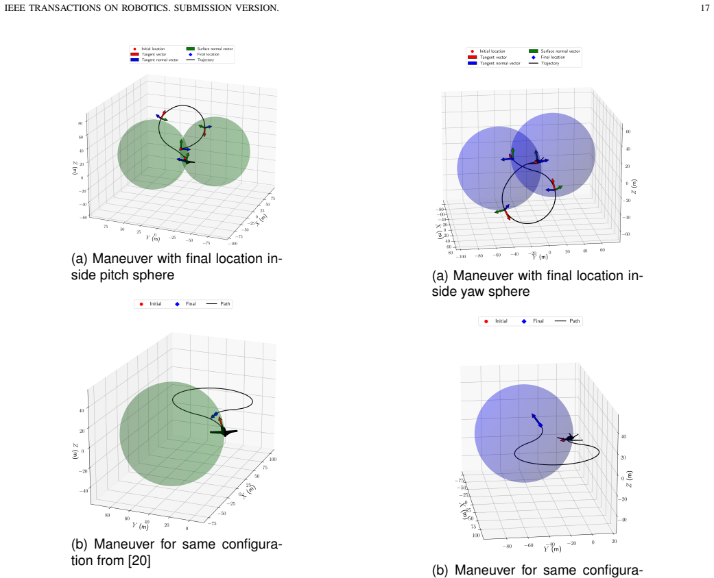
D. P. Kumar, S. Darbha, S. G. Manyam, and D. Casbeer, “A new IEEE TRANSACTIONS ON ROBOTICS. SUBMISSION VERSION. 17 (a) Maneuver with final location in- side pitch sphere (b) Maneuver for same configura- tion from [20] Fig. 21. Depiction of path for final location lying inside pitch sphere approach to motion planning in 3D for a dubins vehicle: Special cas...
work page internal anchor Pith review Pith/arXiv arXiv 2025
-
[24]
There is more than one way to frame a curve,
R. L. Bishop, “There is more than one way to frame a curve,”The American Mathematical Monthly, vol. 82, no. 3, pp. 246–251, 1975
work page 1975
-
[25]
Optimal geodesic curvature constrained dubins’ paths on a sphere,
S. Darbha, A. Pavan, R. Kumbakonam, S. Rathinam, D. W. Casbeer, and S. G. Manyam, “Optimal geodesic curvature constrained dubins’ paths on a sphere,”Journal of Optimization Theory and Applications, vol. 197, pp. 966–992, 2023
work page 2023
-
[26]
Generation of paths for motion planning for a dubins vehicle on sphere,
D. P. Kumar, S. Darbha, S. G. Manyam, and D. Casbeer, “Generation of paths for motion planning for a dubins vehicle on sphere,” 2025. [Online]. Available: https://arxiv.org/abs/2504.11832
-
[27]
D. J. Struik,Lectures on Classical Differential Geometry, 2nd ed. Dover, 1988, ch. 4
work page 1988
-
[28]
Classification of the dubins set,
A. M. Shkel and V . Lumelsky, “Classification of the dubins set,” Robotics and Autonomous Systems, vol. 34, pp. 179–202, 2001
work page 2001
-
[29]
M. P. D. Carmo,Differential Geometry of Curves & Surfaces, 2nd ed. Dover, 2016, ch. 3. APPENDIX A. Construction of segments Consider an intervals∈[s 0, s1]in whichκ g and κn are constants. In this case, noting thatR(s) := T(s)Y(s)U(s) is a rotation matrix, a portion of (2) (a) Maneuver with final location in- side yaw sphere (b) Maneuver for same configur...
work page 2016
discussion (0)
Sign in with ORCID, Apple, or X to comment. Anyone can read and Pith papers without signing in.